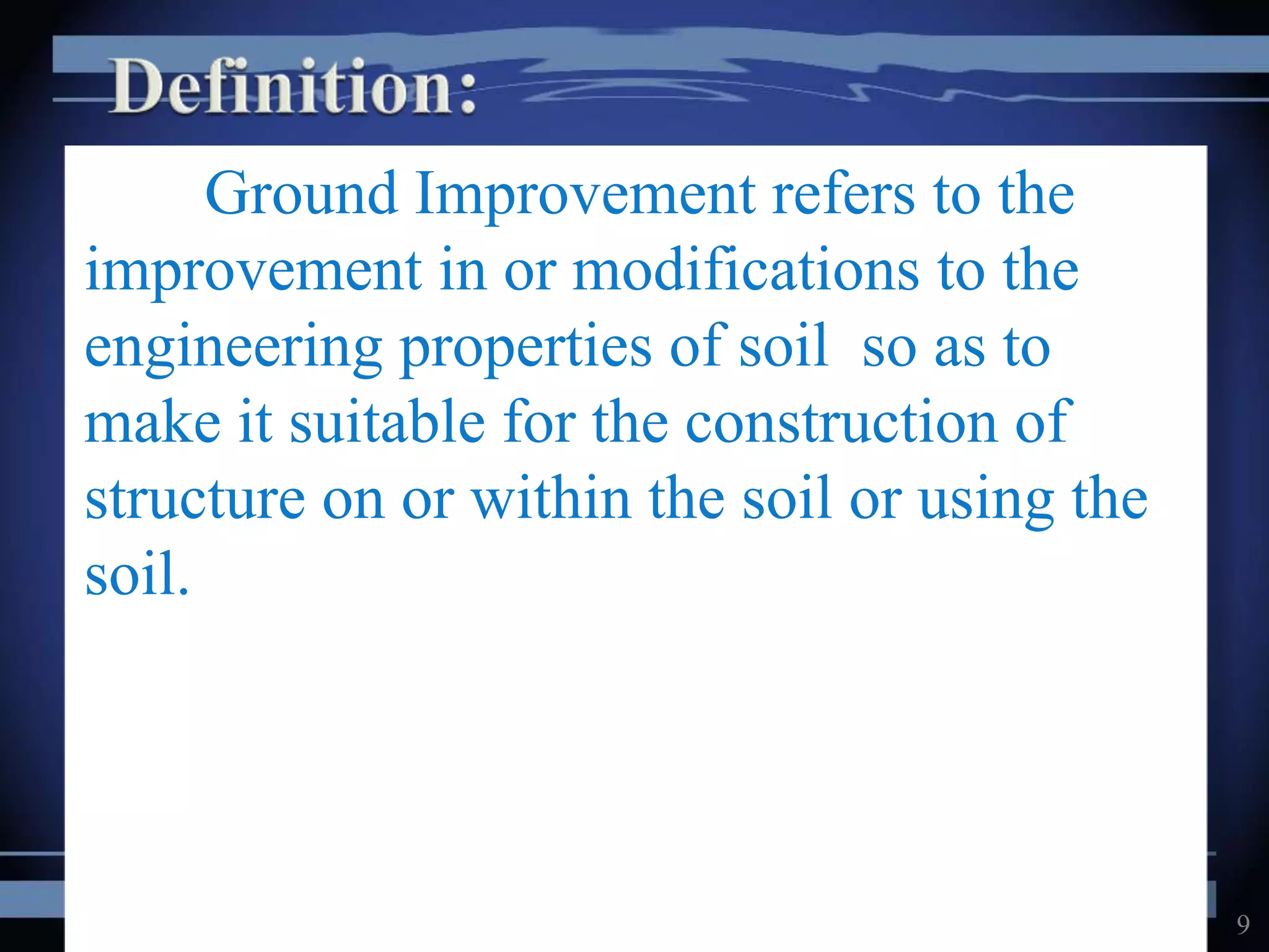
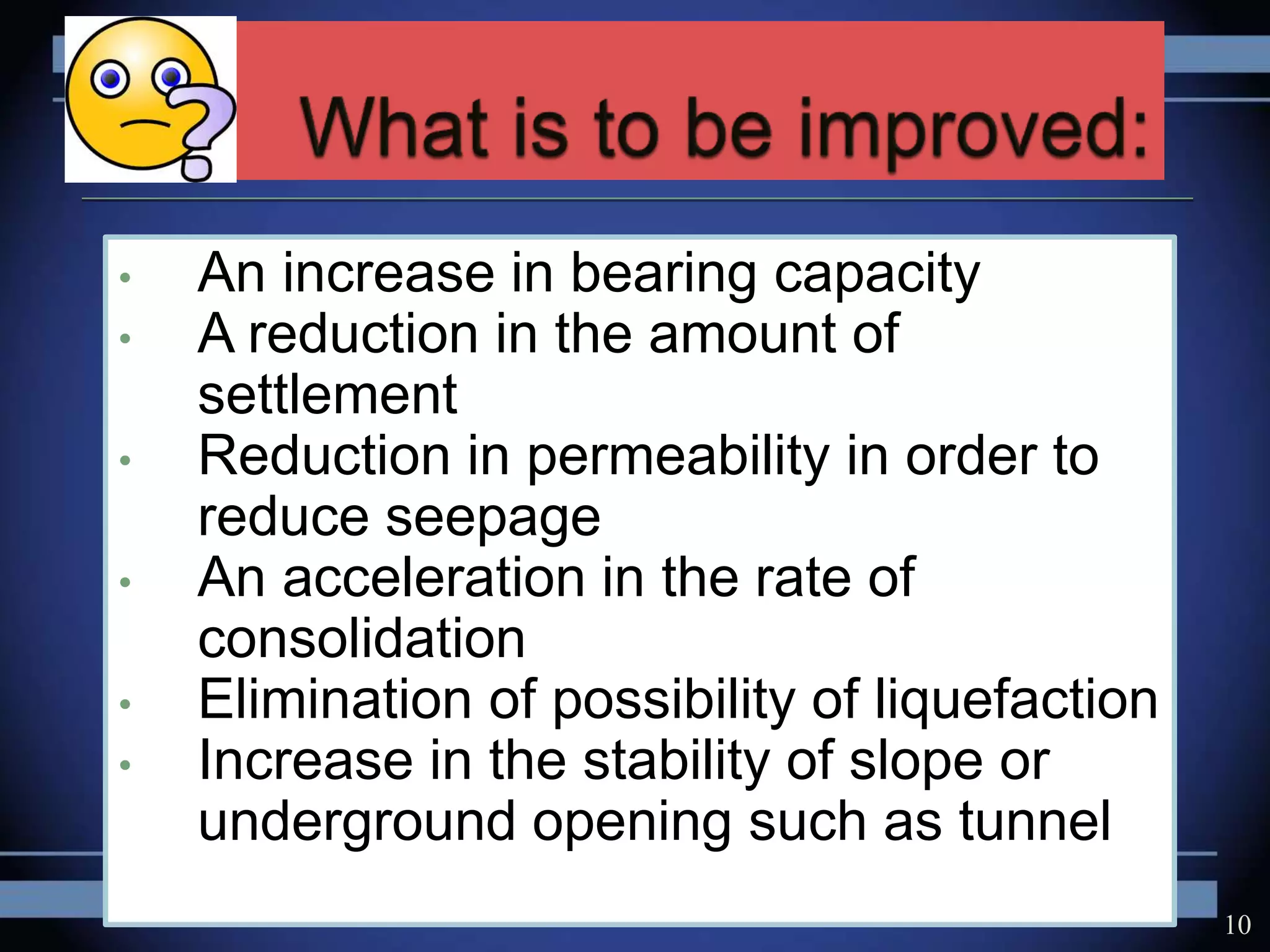
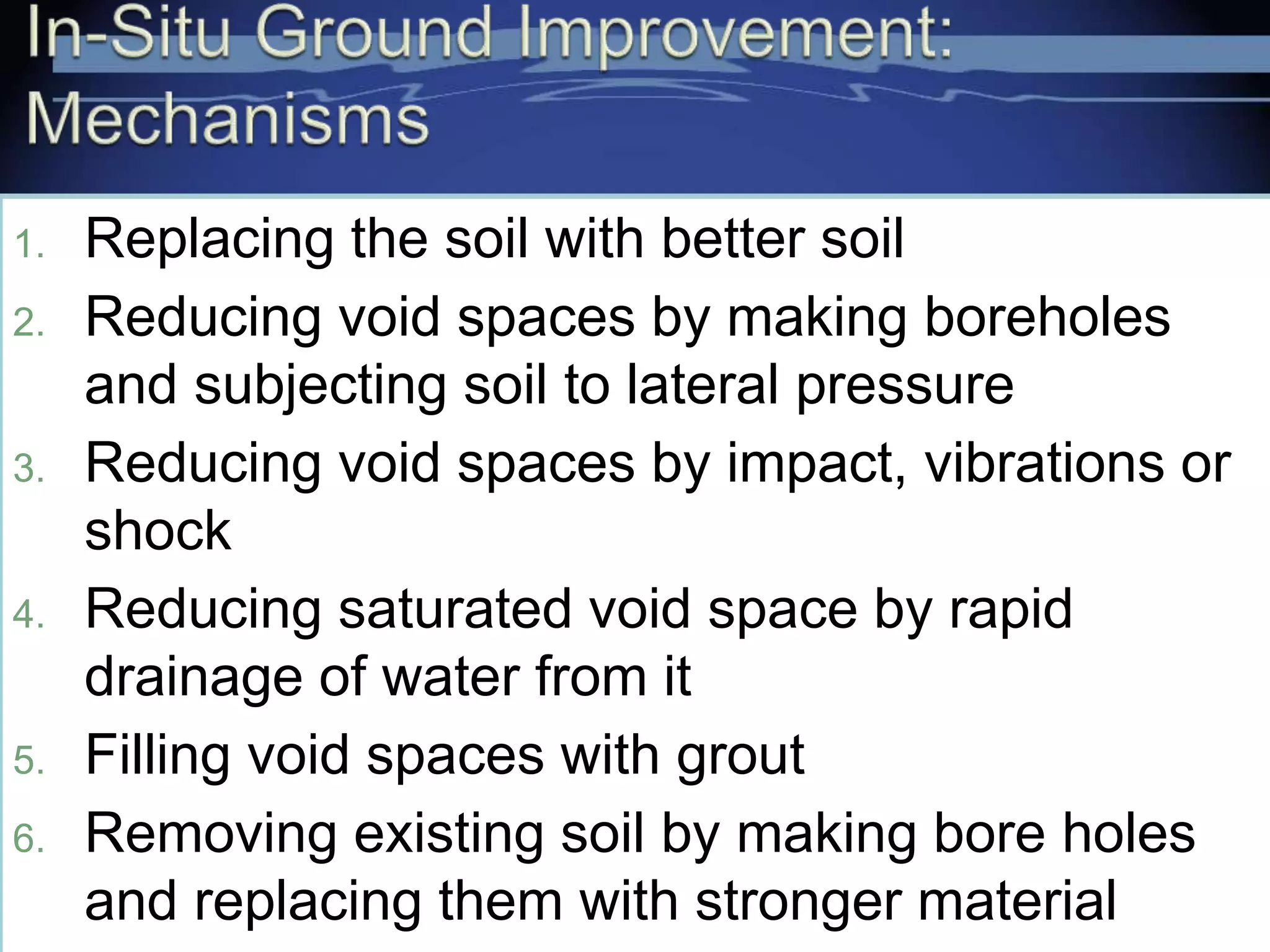
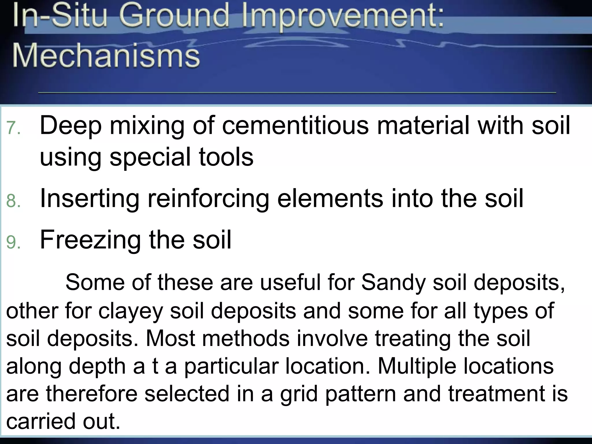
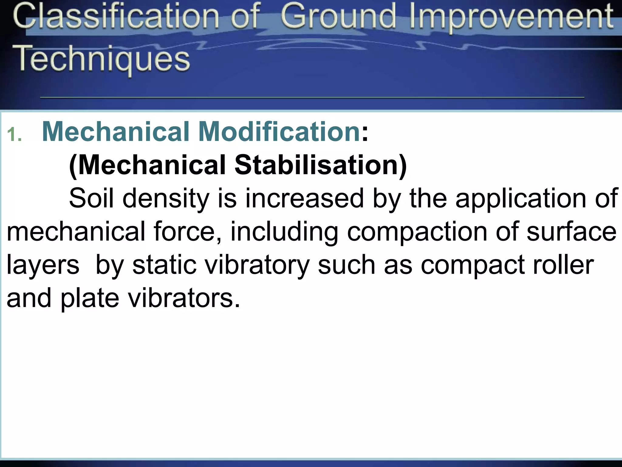
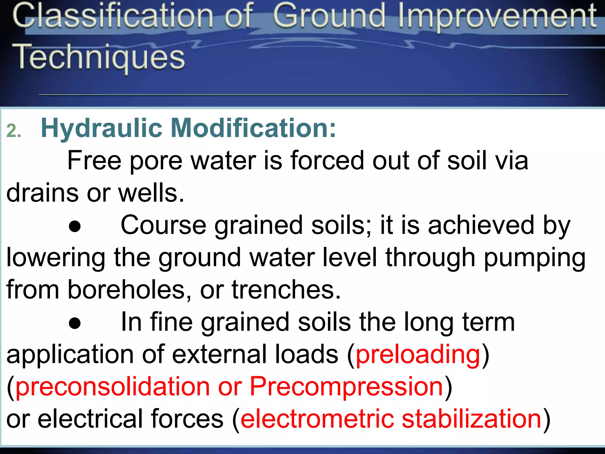
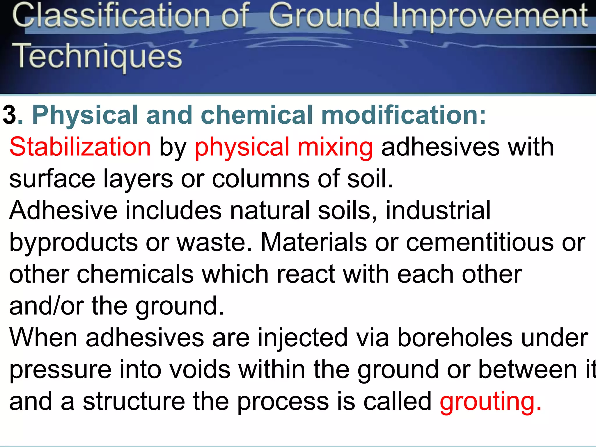
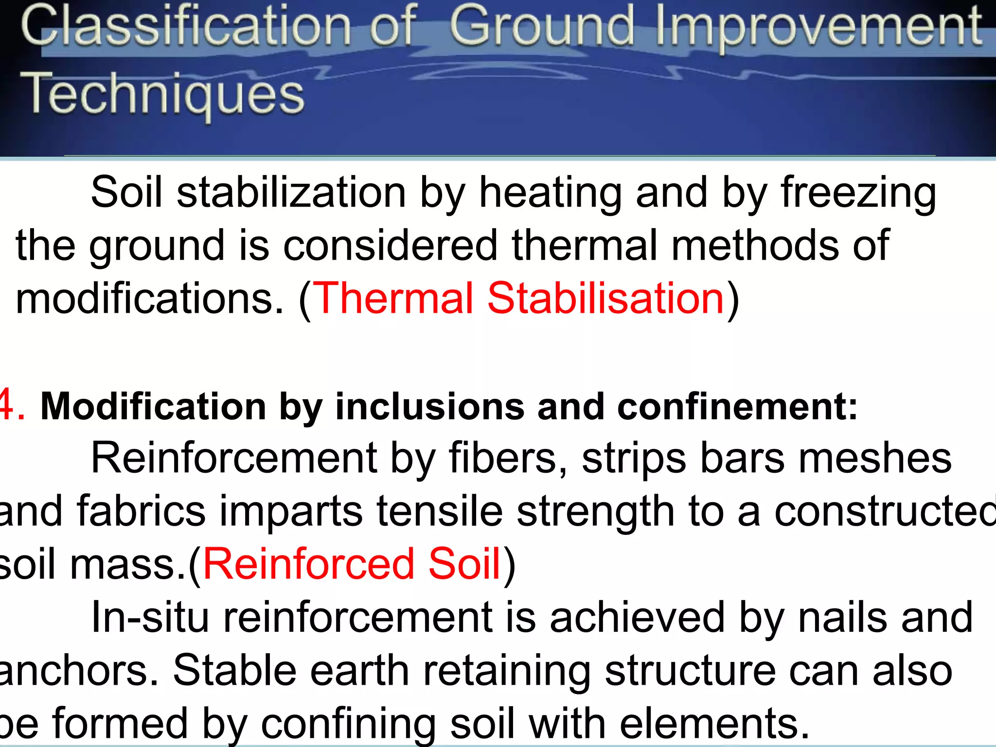
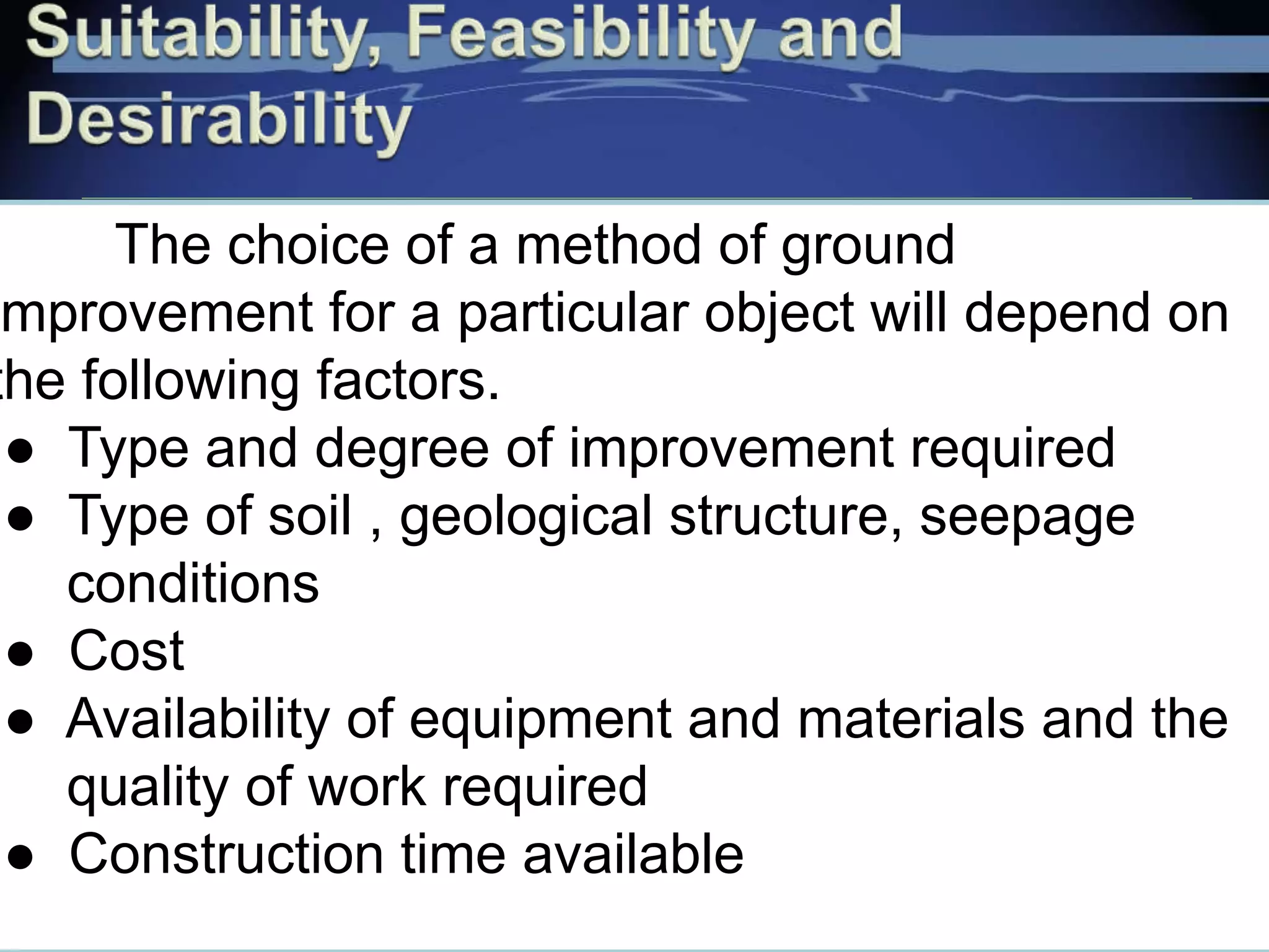
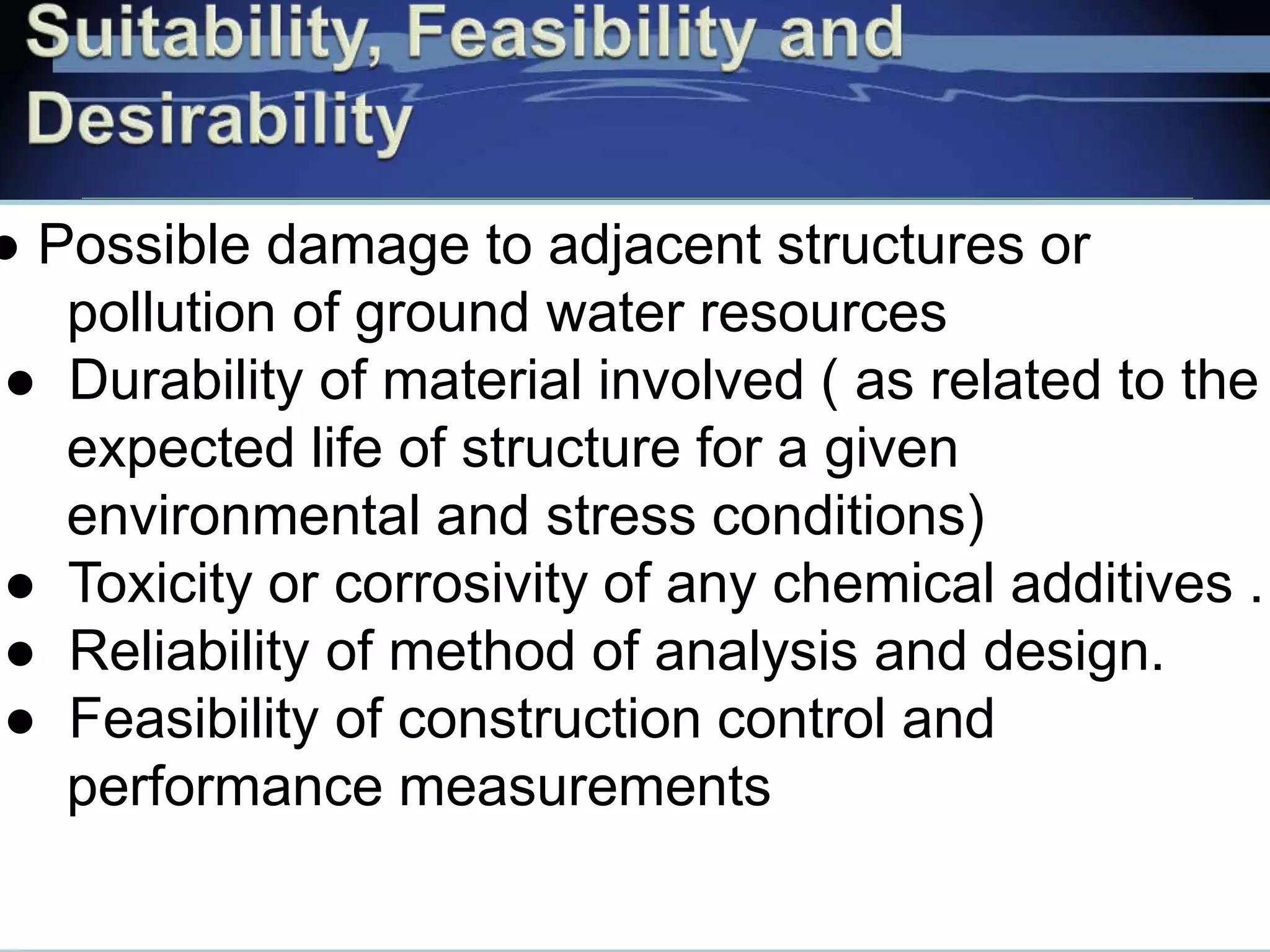
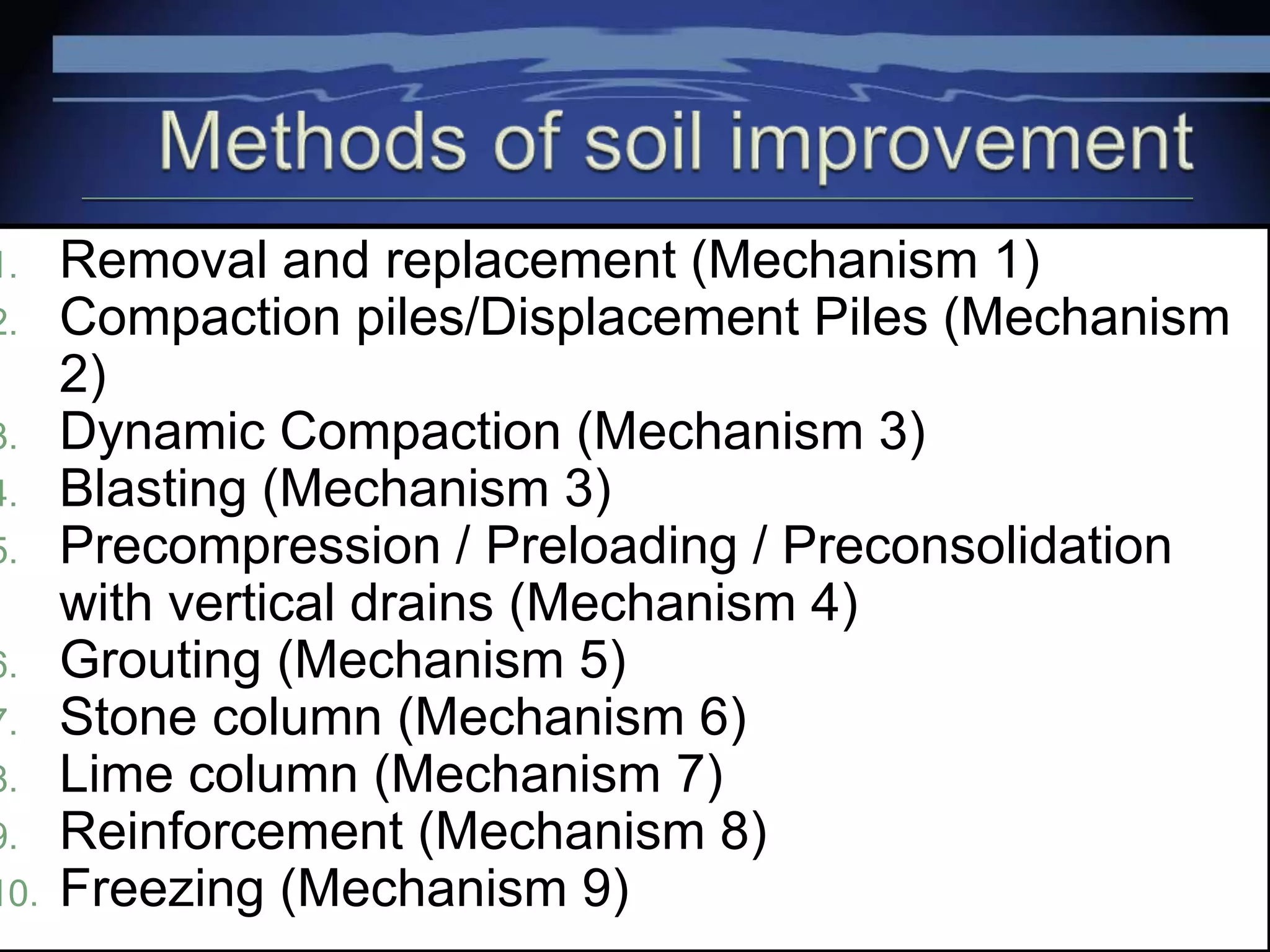
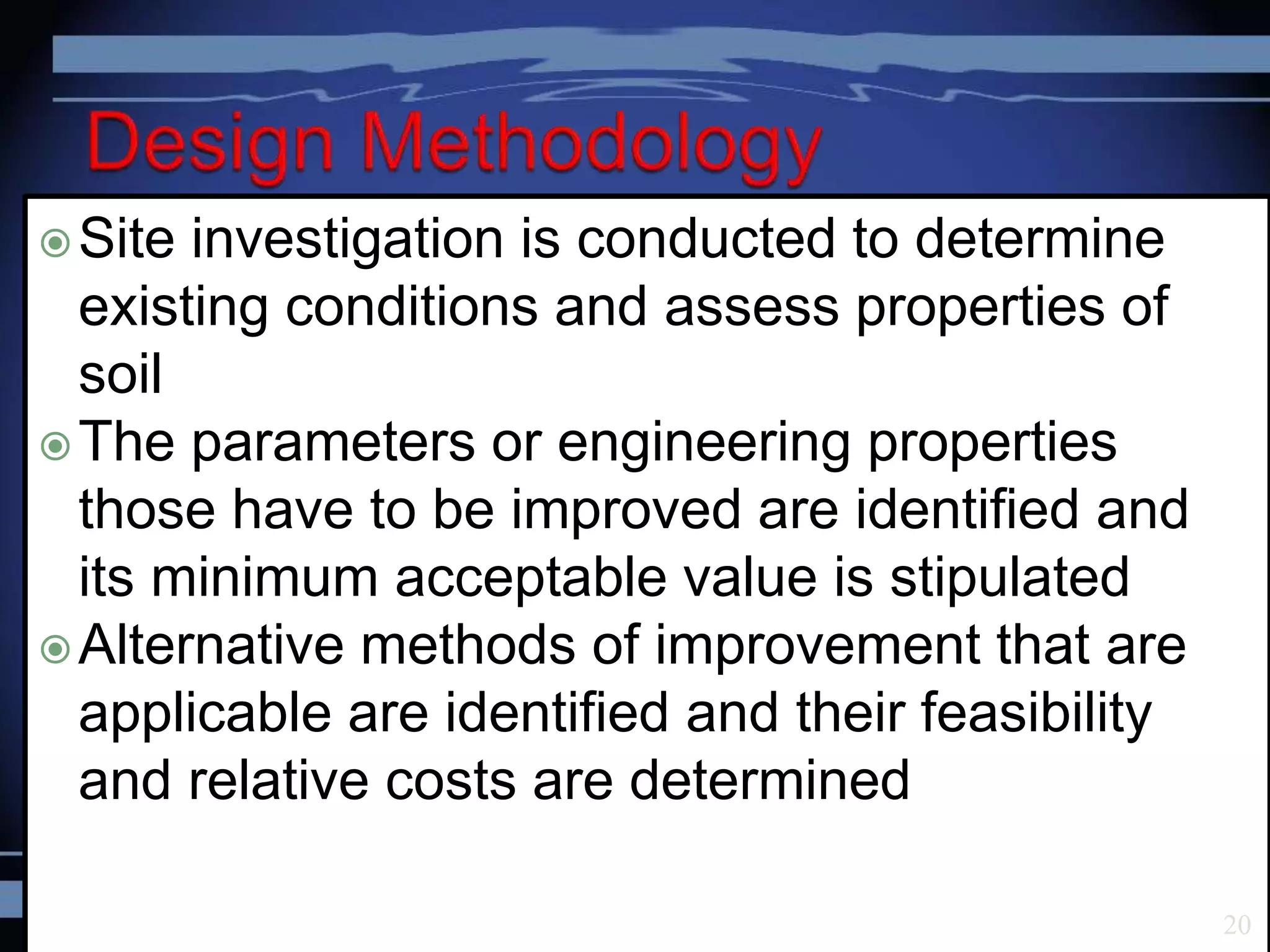
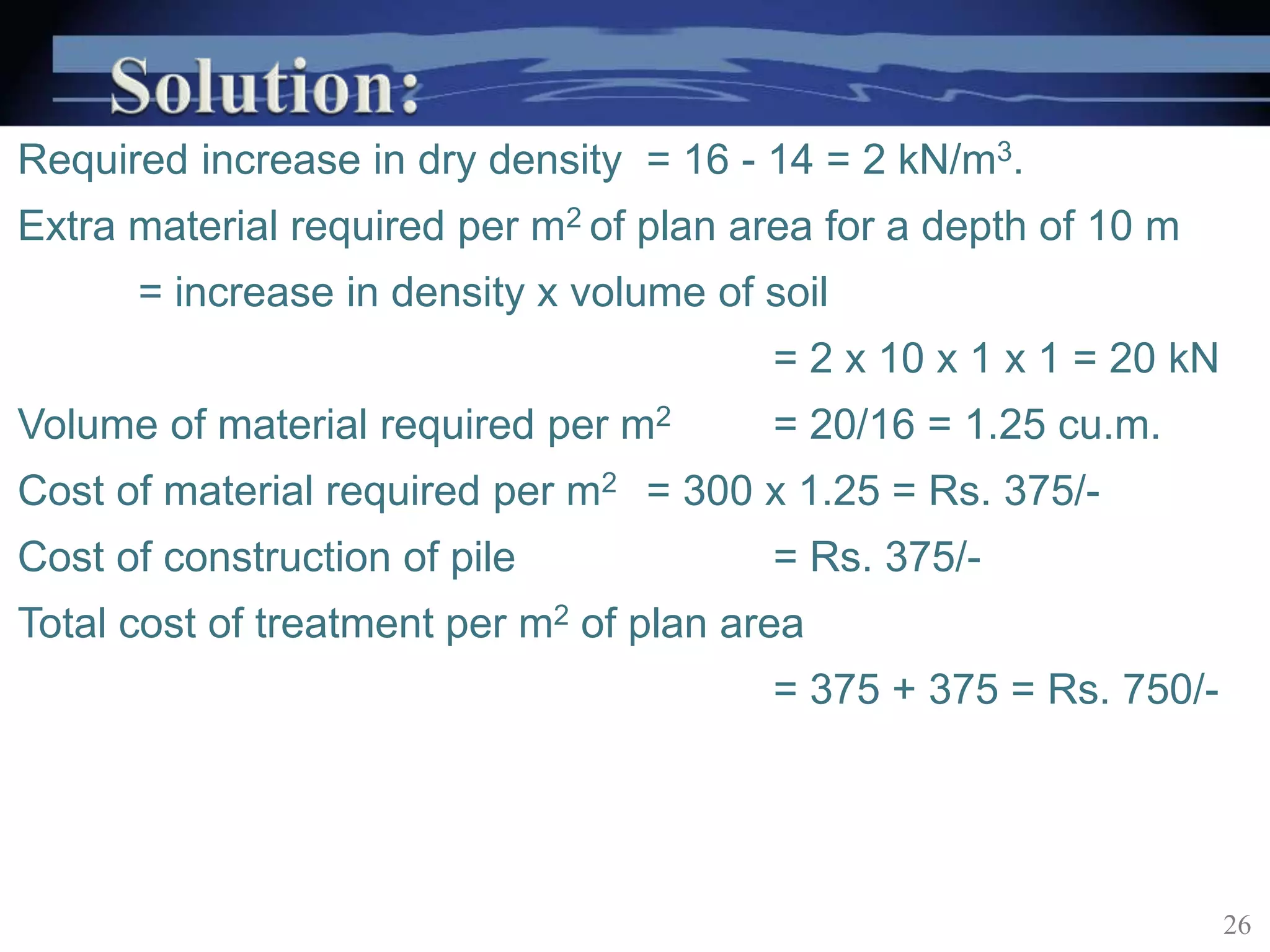
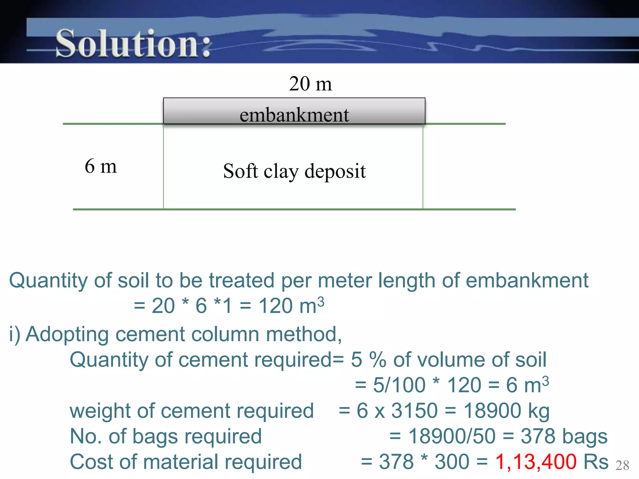
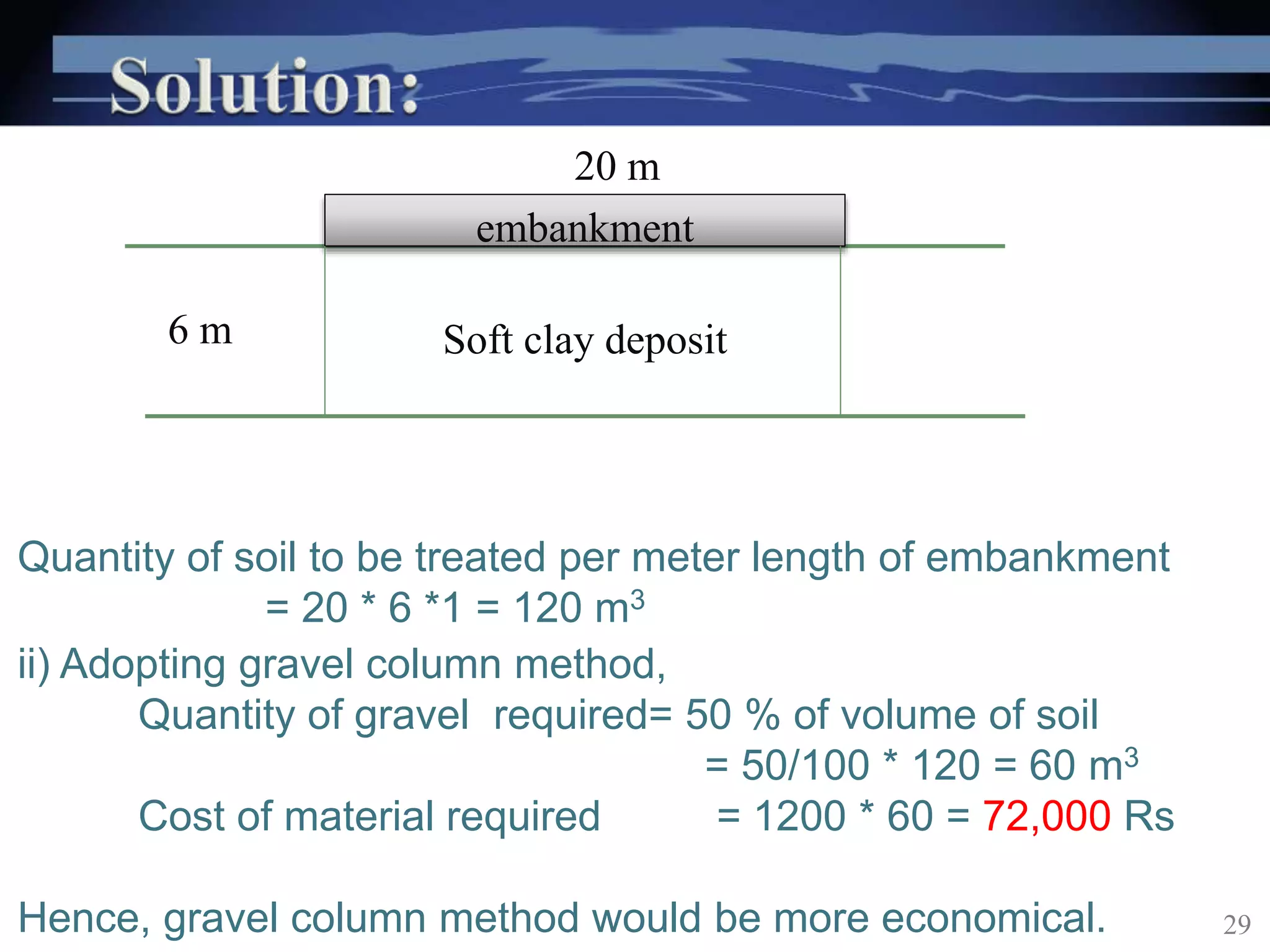
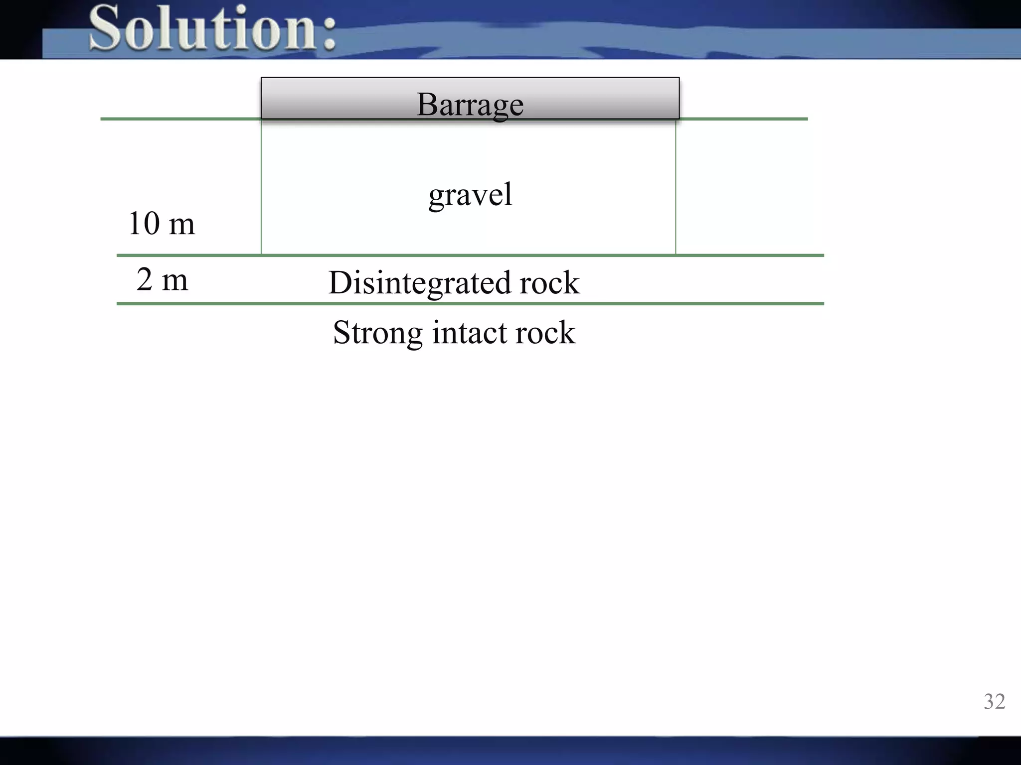
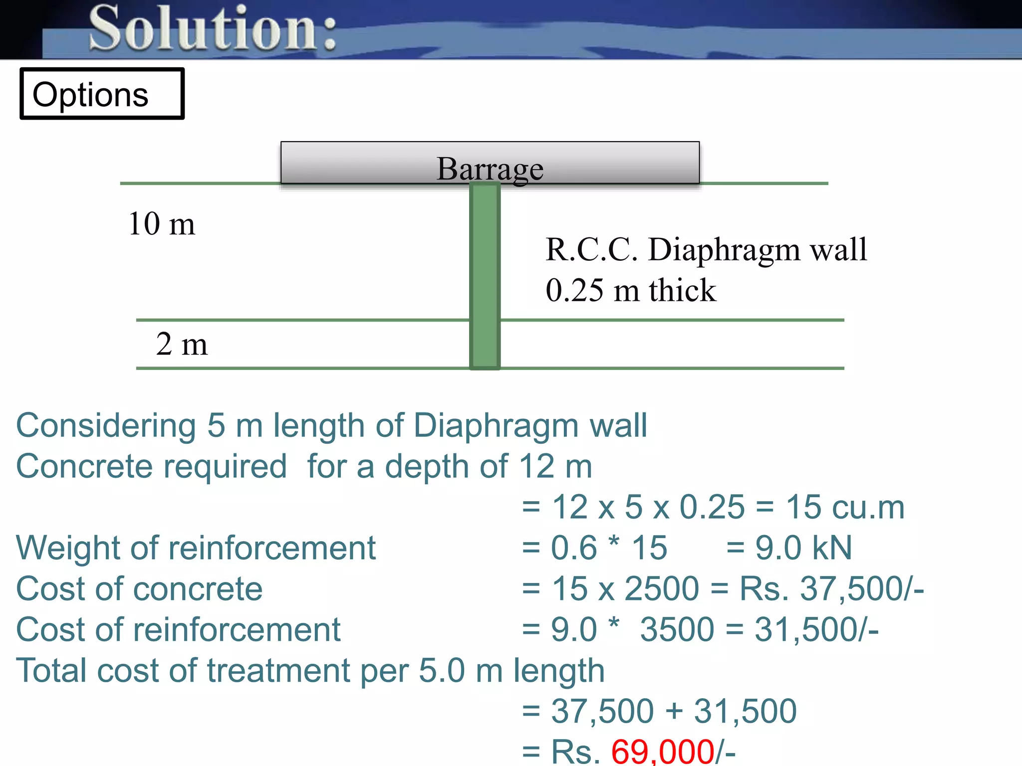
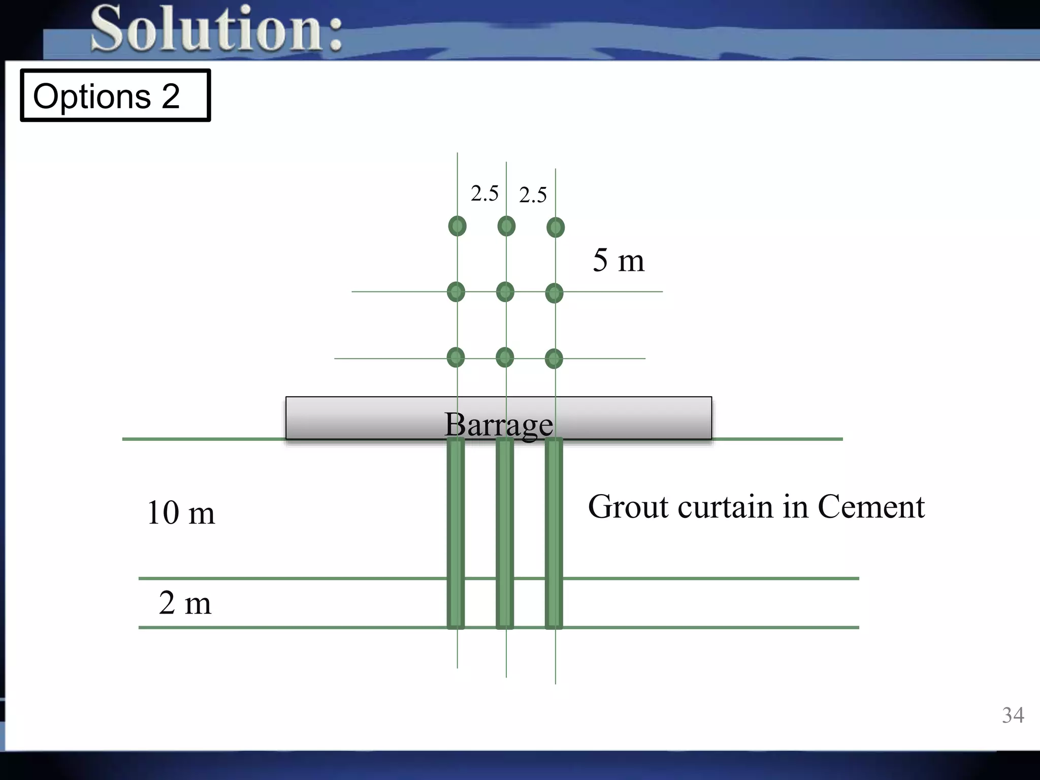
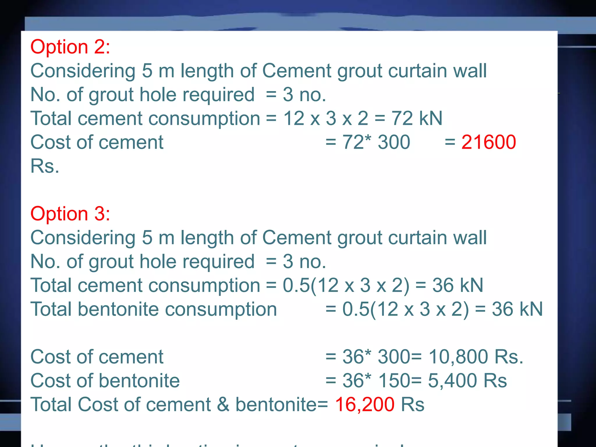
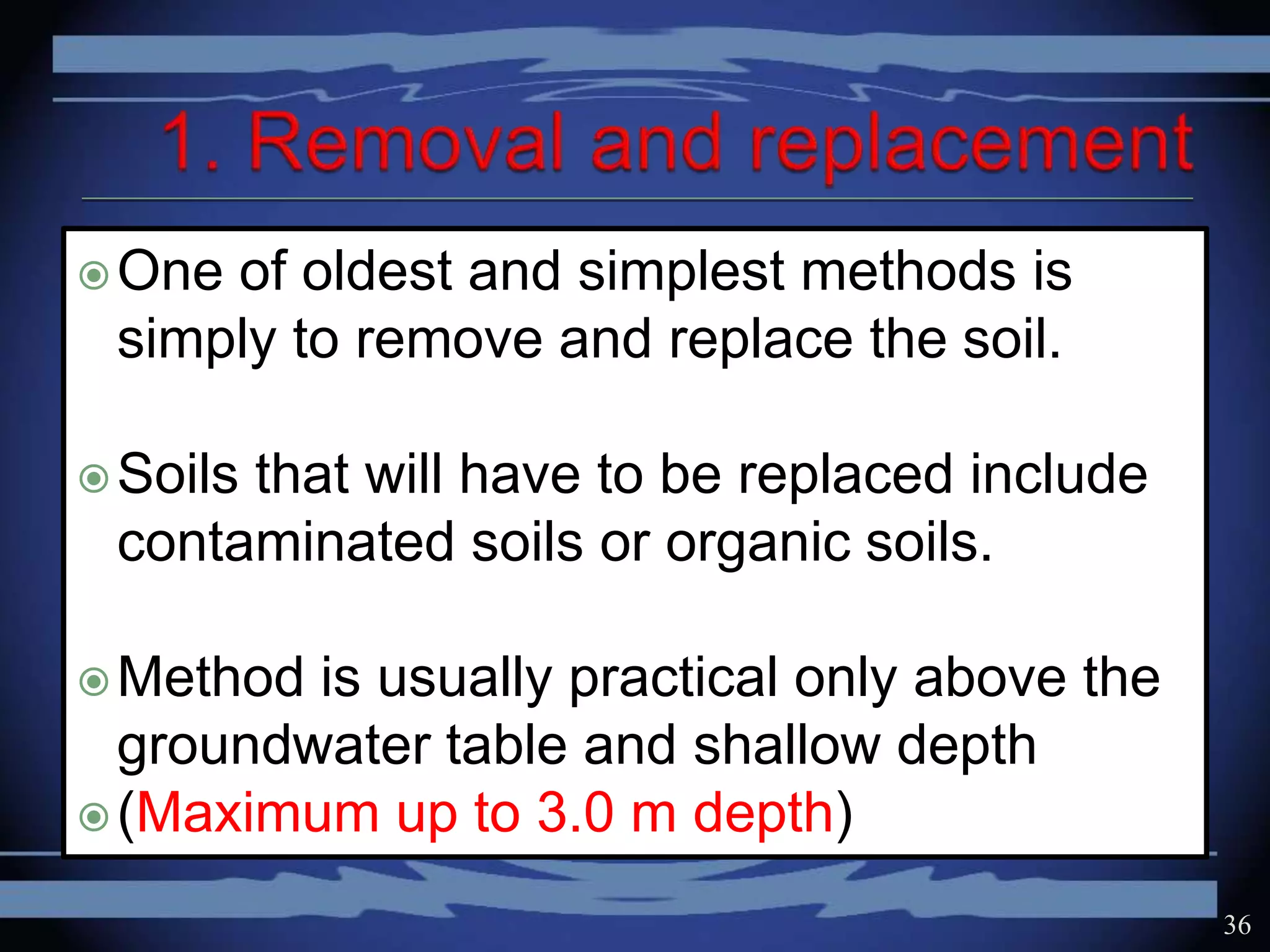
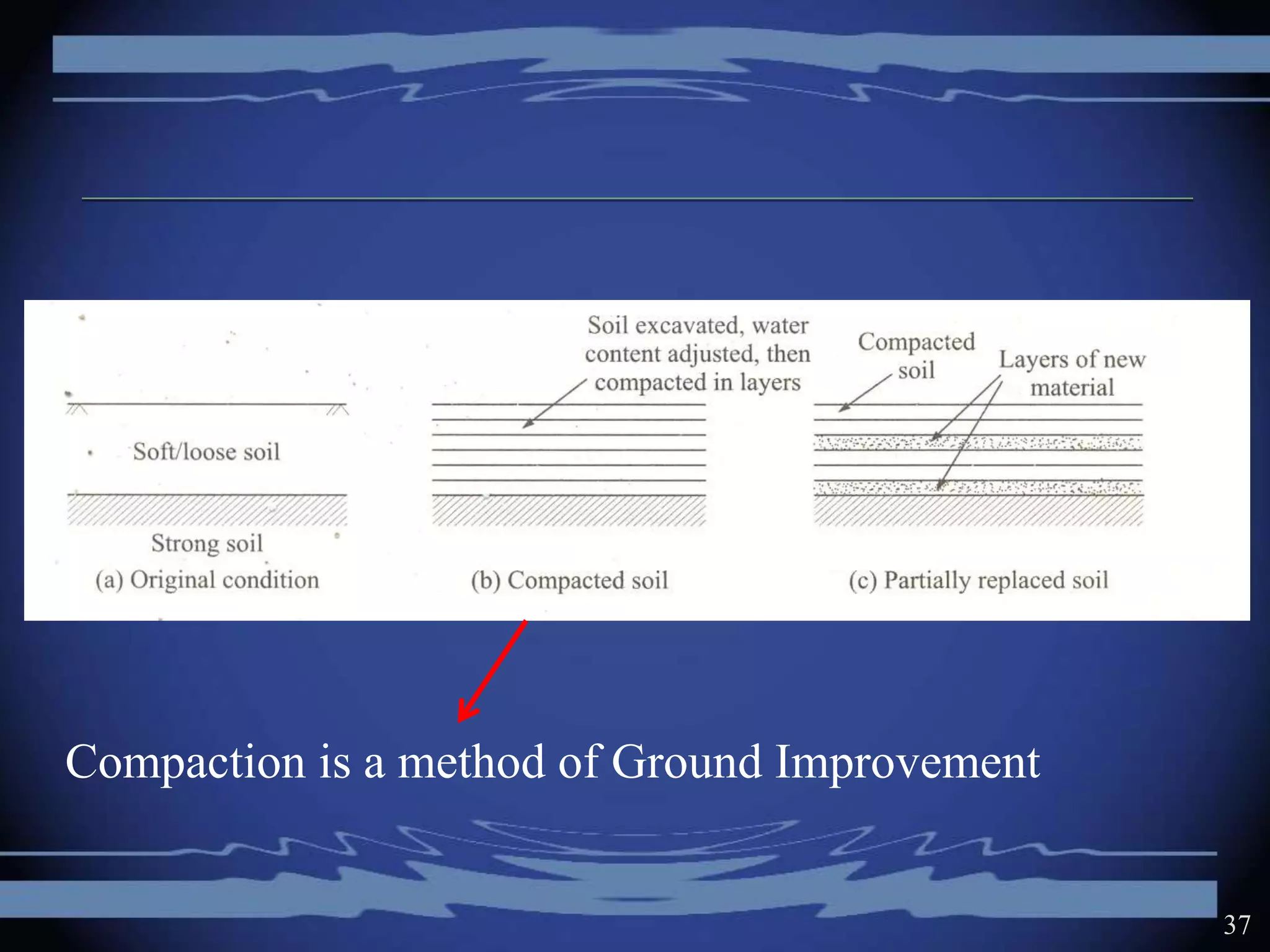
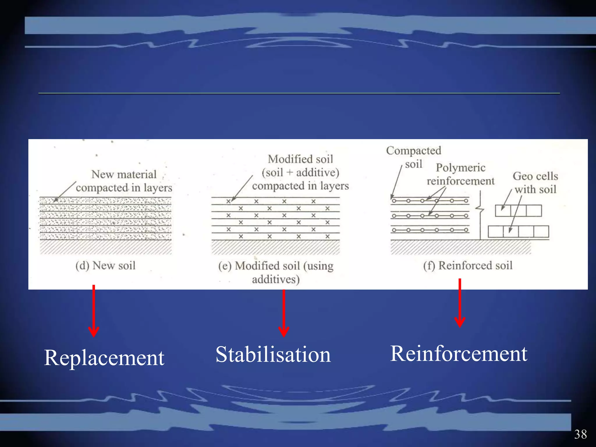
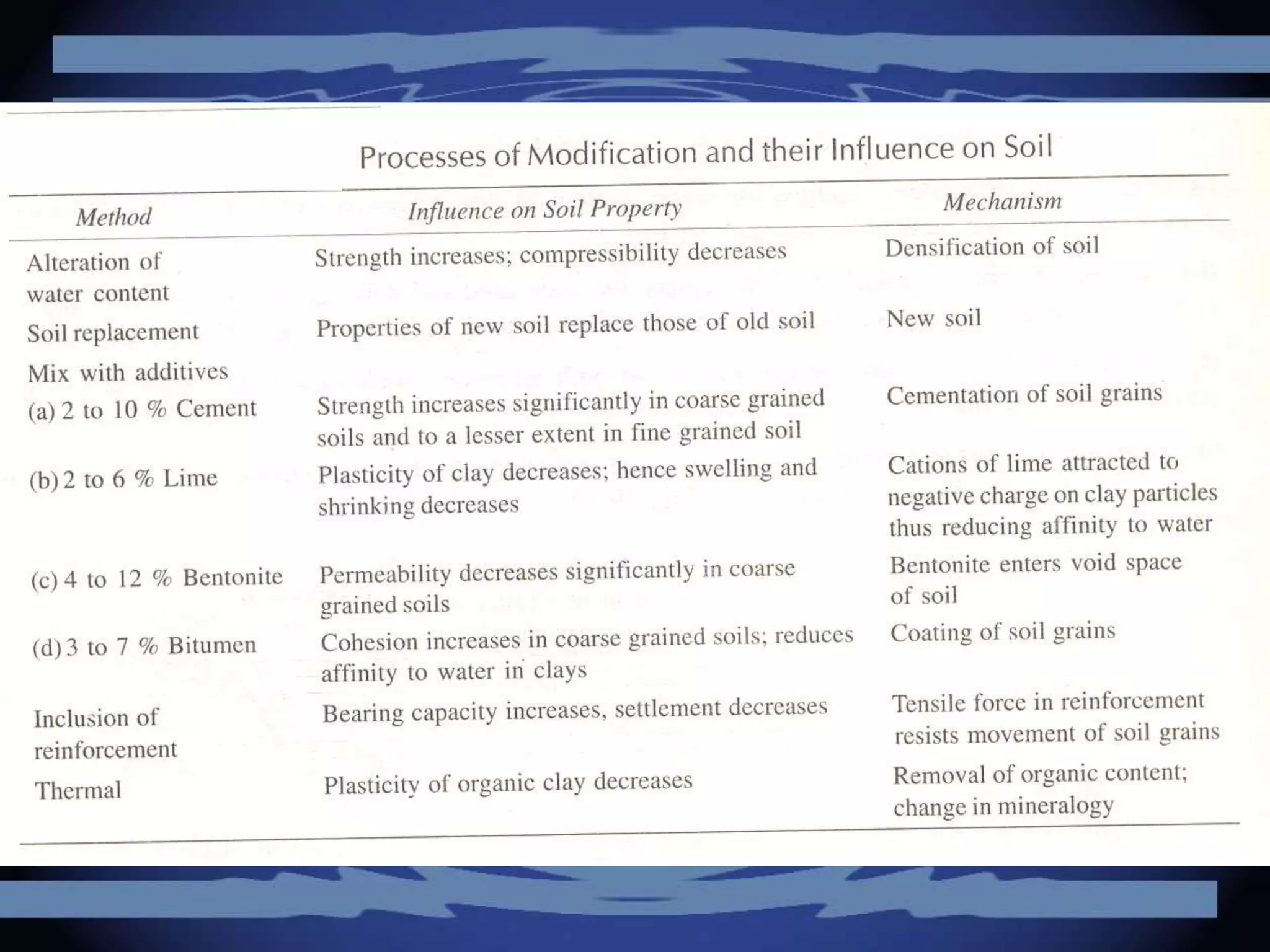
GOVERNMENT COLLEGE OF
ENGINEERING, AMRAVATI
DEPARTMENT OF CIVIL ENGINEERING
GROUND IMPROVEMENT
TECHNIQUE
INTRODUCTION
PROF. S. W. THAKARE
REFERENCES
1. NPTEL NOTES (www.nptel.ac.in)
SOIL DEPOSITS OF INDIA
RIVER GANGA
3
Alluvial deposits of
Ganga River
HILLS
PLAINS
4
5
Unhappy /
problematic
situations
Average
/ not so good-
not so bad
situations
Happy / No
Problem
situations
6
Happy / No Problem situations:
 Ground consisting of hard rock
 Ground with high bearing capacity
 Ground having high values of CBR
• Soft Clays
• Loose sands
• Expansive Soils
• Collapsible Soils
• Seismic Conditions
• Artesian Conditions
• Contaminated Ground
• Unstable Slopes
7
Avoid the site by relocating the structure at a site with
better soil conditions
Adopt the foundation system suitable for the existing
soil condition, so that stresses and settlements are
within permissible limit e.g. raft foundation
Adopt a foundation system that by-passes the poor soil
and transfers the load to strong soil beneath e.g. pile
foundation
Improve or modify the properties of soil by excavating
and replacing with better soil
Improve or modify the properties of soil by insitu soil
treatment 8
Ground Improvement refers to the
improvement in or modifications to the
engineering properties of soil so as to
make it suitable for the construction of
structure on or within the soil or using the
soil.
9
• An increase in bearing capacity
• A reduction in the amount of
settlement
• Reduction in permeability in order to
reduce seepage
• An acceleration in the rate of
consolidation
• Elimination of possibility of liquefaction
• Increase in the stability of slope or
underground opening such as tunnel
10
1. Replacing the soil with better soil
2. Reducing void spaces by making boreholes
and subjecting soil to lateral pressure
3. Reducing void spaces by impact, vibrations or
shock
4. Reducing saturated void space by rapid
drainage of water from it
5. Filling void spaces with grout
6. Removing existing soil by making bore holes
and replacing them with stronger material
7. Deep mixing of cementitious material with soil
using special tools
8. Inserting reinforcing elements into the soil
9. Freezing the soil
Some of these are useful for Sandy soil deposits,
other for clayey soil deposits and some for all types of
soil deposits. Most methods involve treating the soil
along depth a t a particular location. Multiple locations
are therefore selected in a grid pattern and treatment is
carried out.
1. Mechanical Modification:
(Mechanical Stabilisation)
Soil density is increased by the application of
mechanical force, including compaction of surface
layers by static vibratory such as compact roller
and plate vibrators.
2. Hydraulic Modification:
Free pore water is forced out of soil via
drains or wells.
● Course grained soils; it is achieved by
lowering the ground water level through pumping
from boreholes, or trenches.
● In fine grained soils the long term
application of external loads (preloading)
(preconsolidation or Precompression)
or electrical forces (electrometric stabilization)
3. Physical and chemical modification:
Stabilization by physical mixing adhesives with
surface layers or columns of soil.
Adhesive includes natural soils, industrial
byproducts or waste. Materials or cementitious or
other chemicals which react with each other
and/or the ground.
When adhesives are injected via boreholes under
pressure into voids within the ground or between it
and a structure the process is called grouting.
Soil stabilization by heating and by freezing
the ground is considered thermal methods of
modifications. (Thermal Stabilisation)
4. Modification by inclusions and confinement:
Reinforcement by fibers, strips bars meshes
and fabrics imparts tensile strength to a constructed
soil mass.(Reinforced Soil)
In-situ reinforcement is achieved by nails and
anchors. Stable earth retaining structure can also
be formed by confining soil with elements.
The choice of a method of ground
improvement for a particular object will depend on
the following factors.
● Type and degree of improvement required
● Type of soil , geological structure, seepage
conditions
● Cost
● Availability of equipment and materials and the
quality of work required
● Construction time available
● Possible damage to adjacent structures or
pollution of ground water resources
● Durability of material involved ( as related to the
expected life of structure for a given
environmental and stress conditions)
● Toxicity or corrosivity of any chemical additives .
● Reliability of method of analysis and design.
● Feasibility of construction control and
performance measurements
1. Removal and replacement (Mechanism 1)
2. Compaction piles/Displacement Piles (Mechanism
2)
3. Dynamic Compaction (Mechanism 3)
4. Blasting (Mechanism 3)
5. Precompression / Preloading / Preconsolidation
with vertical drains (Mechanism 4)
6. Grouting (Mechanism 5)
7. Stone column (Mechanism 6)
8. Lime column (Mechanism 7)
9. Reinforcement (Mechanism 8)
10. Freezing (Mechanism 9)
Site investigation is conducted to determine
existing conditions and assess properties of
soil
The parameters or engineering properties
those have to be improved are identified and
its minimum acceptable value is stipulated
Alternative methods of improvement that are
applicable are identified and their feasibility
and relative costs are determined
20
For the most suitable method, preliminary
design is carried out and construction variables
are evaluated
Fields trials are undertaken by executing the
ground improvement on a small test patch and
then assessing the value of the parameter or
engineering property that had to be improved
On the basis of the results obtained from field
trials, necessary adjustments are made in the
construction variables. Full scale operations
are then undertaken
21
Site investigations at a site reveal that soil beneath the ground
surface comprises of loose' sand down to a depth of 3.5 m
followed by a dense stratum. For ground improvement, there are
two options under consideration:
(i) densification by impact compaction and
(ii) densification by excavation and relaying in layers using
vibratory rollers for compaction.
The cost of impact compaction is estimated at Rs. 350/- per
m2 of plan area of the site. For excavation, the prevalent unit rate
is Rs. 30/- per m3 and for relaying soil with compaction, the rate is
Rs. 45/- per m3.
(a)Which method will be· more economical?
(b) What other factors should be considered before selecting the
method to be used? 22
(a) (i)For one m2 of plan area, the amount of soil to be excavated
and relayed = 1.0 x 1.0 x 3.5 = 3.5 m3.
Cost of excavating and relaying 3.5 m3 of soil
= 3.5 (30 + 45) = Rs. 262.50
Hence cost of excavation and relaying = Rs. 262.50 per m2
(ii) Cost of impact compaction = 350 per m2 plan area.
Hence impact compaction is more costly.
(b) Other factors to be considered for selection of methods:
(i) Does the water table lie above or below 3.5 m depth?
(ii) Is sufficient space available around the site to make inclined
cuts (1.5 (hor.) 1.0 (ver)?
(iii) Are there any buildings close to the site, say within 50 m
distance?
23
If water table is high or sufficient space is not available for
making a cut along an inclined slope, then impact compaction
may be adopted.
If buildings are close to the site, impact compaction can
cause vibrations in the buildings and should be avoided.
When time available for completion of work is limited, faster
method may be chosen even if it is more expensive because early
commissioning of the project often offsets the extra cost incurred.
24
The density of a 10 m deep loose sand deposit is
to be increased by compaction piles. Estimate the
amount of extra material that will have to be added to
the soil per m2 of plan area if the dry density of the
soil is to be increased from 14 kN/m3 to 16 kN/m3. If the
material to be added costs Rs. 300/- per m3, and the
cost of constructing the compaction piles is 100% of the
cost of material, what is the cost of treatment per
m2 of plan area
25
Required increase in dry density = 16 - 14 = 2 kN/m3.
Extra material required per m2 of plan area for a depth of 10 m
= increase in density x volume of soil
= 2 x 10 x 1 x 1 = 20 kN
Volume of material required per m2 = 20/16 = 1.25 cu.m.
Cost of material required per m2 = 300 x 1.25 = Rs. 375/-
Cost of construction of pile = Rs. 375/-
Total cost of treatment per m2 of plan area
= 375 + 375 = Rs. 750/-
26
A very soft clay deposit, over which a road
embankment that is 20 m wide at ground level is to be
constructed, can be stabilized (i) by constructing
overlapping columns of clay with 5% cement
using deep mixing technique or (ii) by replacing 50% of
clay by gravel columns using stone column
technique. The clay deposit is 6 m deep. Compare the
cost of treatment if gravel is available at Rs. 1200 per
m3. and cement is available at Rs. 300 per 50 kg bag of
cement. The cost of constructing cement columns or
gravel columns is about the same and only the cost of
materials needs to be considered.
27
Quantity of soil to be treated per meter length of embankment
= 20 * 6 *1 = 120 m3
i) Adopting cement column method,
Quantity of cement required= 5 % of volume of soil
= 5/100 * 120 = 6 m3
weight of cement required = 6 x 3150 = 18900 kg
No. of bags required = 18900/50 = 378 bags
Cost of material required = 378 * 300 = 1,13,400 Rs 28
embankment
20 m
6 m Soft clay deposit
Quantity of soil to be treated per meter length of embankment
= 20 * 6 *1 = 120 m3
ii) Adopting gravel column method,
Quantity of gravel required= 50 % of volume of soil
= 50/100 * 120 = 60 m3
Cost of material required = 1200 * 60 = 72,000 Rs
Hence, gravel column method would be more economical. 29
embankment
20 m
6 m Soft clay deposit
A vertical cut-off wall (seepage barrier) is to be
constructed to a depth of 12 m below a barrage
where the subsoil is gravel down to 10 m depth
underlain by 2 m thick disintegrated rock and then
strong intact rock. The following alternatives are being
considered. (a) RCC diaphragm wall (b) grout
curtain of cement (c) grout curtain of cement + Bentonite
(1:1).
The diaphragm wall will be 250 mm thick. The
grout curtain will comprise of 3 rows of grout holes
spaced at a distance of 2.5 m from each other. Along
each row, the grout holes will be spaced 5 m.
apart. 30
The grout intake (dry cement or cement +
bentonite) is estimated as 2 kN/m length of each
hole (slurry water is extra). Determine the cost of each
alternative given that
a) cost of concrete per m3 is Rs. 2500/- (density 24
kN/m3),
b) cost of reinforcement is Rs. 3500/- per kN (0.6 kN
per m3 reinforcement in wall),
c) cost of cement is Rs. 300/- per kN
d) cost of Bentonite is Rs. 150/- per kN,
e) cost of construction of diaphragm wall and grouting
may be taken as similar. 31
32
10 m
Barrage
gravel
2 m Disintegrated rock
Strong intact rock
33
10 m
Barrage
2 m
R.C.C. Diaphragm wall
0.25 m thick
Options
Considering 5 m length of Diaphragm wall
Concrete required for a depth of 12 m
= 12 x 5 x 0.25 = 15 cu.m
Weight of reinforcement = 0.6 * 15 = 9.0 kN
Cost of concrete = 15 x 2500 = Rs. 37,500/-
Cost of reinforcement = 9.0 * 3500 = 31,500/-
Total cost of treatment per 5.0 m length
= 37,500 + 31,500
= Rs. 69,000/-
34
10 m
Options 2
Barrage
2 m
Grout curtain in Cement
5 m
2.52.5
Option 2:
Considering 5 m length of Cement grout curtain wall
No. of grout hole required = 3 no.
Total cement consumption = 12 x 3 x 2 = 72 kN
Cost of cement = 72* 300 = 21600
Rs.
Option 3:
Considering 5 m length of Cement grout curtain wall
No. of grout hole required = 3 no.
Total cement consumption = 0.5(12 x 3 x 2) = 36 kN
Total bentonite consumption = 0.5(12 x 3 x 2) = 36 kN
Cost of cement = 36* 300= 10,800 Rs.
Cost of bentonite = 36* 150= 5,400 Rs
Total Cost of cement & bentonite= 16,200 Rs
One of oldest and simplest methods is
simply to remove and replace the soil.
Soils that will have to be replaced include
contaminated soils or organic soils.
Method is usually practical only above the
groundwater table and shallow depth
(Maximum up to 3.0 m depth)
36
37
Compaction is a method of Ground Improvement
38
StabilisationReplacement Reinforcement
Ground imrovement   introduction

Ground imrovement introduction

  • 1.
    GOVERNMENT COLLEGE OF ENGINEERING,AMRAVATI DEPARTMENT OF CIVIL ENGINEERING GROUND IMPROVEMENT TECHNIQUE INTRODUCTION PROF. S. W. THAKARE
  • 2.
    REFERENCES 1. NPTEL NOTES(www.nptel.ac.in)
  • 3.
    SOIL DEPOSITS OFINDIA RIVER GANGA 3
  • 4.
    Alluvial deposits of GangaRiver HILLS PLAINS 4
  • 5.
    5 Unhappy / problematic situations Average / notso good- not so bad situations Happy / No Problem situations
  • 6.
    6 Happy / NoProblem situations:  Ground consisting of hard rock  Ground with high bearing capacity  Ground having high values of CBR
  • 7.
    • Soft Clays •Loose sands • Expansive Soils • Collapsible Soils • Seismic Conditions • Artesian Conditions • Contaminated Ground • Unstable Slopes 7
  • 8.
    Avoid the siteby relocating the structure at a site with better soil conditions Adopt the foundation system suitable for the existing soil condition, so that stresses and settlements are within permissible limit e.g. raft foundation Adopt a foundation system that by-passes the poor soil and transfers the load to strong soil beneath e.g. pile foundation Improve or modify the properties of soil by excavating and replacing with better soil Improve or modify the properties of soil by insitu soil treatment 8
  • 9.
    Ground Improvement refersto the improvement in or modifications to the engineering properties of soil so as to make it suitable for the construction of structure on or within the soil or using the soil. 9
  • 10.
    • An increasein bearing capacity • A reduction in the amount of settlement • Reduction in permeability in order to reduce seepage • An acceleration in the rate of consolidation • Elimination of possibility of liquefaction • Increase in the stability of slope or underground opening such as tunnel 10
  • 11.
    1. Replacing thesoil with better soil 2. Reducing void spaces by making boreholes and subjecting soil to lateral pressure 3. Reducing void spaces by impact, vibrations or shock 4. Reducing saturated void space by rapid drainage of water from it 5. Filling void spaces with grout 6. Removing existing soil by making bore holes and replacing them with stronger material
  • 12.
    7. Deep mixingof cementitious material with soil using special tools 8. Inserting reinforcing elements into the soil 9. Freezing the soil Some of these are useful for Sandy soil deposits, other for clayey soil deposits and some for all types of soil deposits. Most methods involve treating the soil along depth a t a particular location. Multiple locations are therefore selected in a grid pattern and treatment is carried out.
  • 13.
    1. Mechanical Modification: (MechanicalStabilisation) Soil density is increased by the application of mechanical force, including compaction of surface layers by static vibratory such as compact roller and plate vibrators.
  • 14.
    2. Hydraulic Modification: Freepore water is forced out of soil via drains or wells. ● Course grained soils; it is achieved by lowering the ground water level through pumping from boreholes, or trenches. ● In fine grained soils the long term application of external loads (preloading) (preconsolidation or Precompression) or electrical forces (electrometric stabilization)
  • 15.
    3. Physical andchemical modification: Stabilization by physical mixing adhesives with surface layers or columns of soil. Adhesive includes natural soils, industrial byproducts or waste. Materials or cementitious or other chemicals which react with each other and/or the ground. When adhesives are injected via boreholes under pressure into voids within the ground or between it and a structure the process is called grouting.
  • 16.
    Soil stabilization byheating and by freezing the ground is considered thermal methods of modifications. (Thermal Stabilisation) 4. Modification by inclusions and confinement: Reinforcement by fibers, strips bars meshes and fabrics imparts tensile strength to a constructed soil mass.(Reinforced Soil) In-situ reinforcement is achieved by nails and anchors. Stable earth retaining structure can also be formed by confining soil with elements.
  • 17.
    The choice ofa method of ground improvement for a particular object will depend on the following factors. ● Type and degree of improvement required ● Type of soil , geological structure, seepage conditions ● Cost ● Availability of equipment and materials and the quality of work required ● Construction time available
  • 18.
    ● Possible damageto adjacent structures or pollution of ground water resources ● Durability of material involved ( as related to the expected life of structure for a given environmental and stress conditions) ● Toxicity or corrosivity of any chemical additives . ● Reliability of method of analysis and design. ● Feasibility of construction control and performance measurements
  • 19.
    1. Removal andreplacement (Mechanism 1) 2. Compaction piles/Displacement Piles (Mechanism 2) 3. Dynamic Compaction (Mechanism 3) 4. Blasting (Mechanism 3) 5. Precompression / Preloading / Preconsolidation with vertical drains (Mechanism 4) 6. Grouting (Mechanism 5) 7. Stone column (Mechanism 6) 8. Lime column (Mechanism 7) 9. Reinforcement (Mechanism 8) 10. Freezing (Mechanism 9)
  • 20.
    Site investigation isconducted to determine existing conditions and assess properties of soil The parameters or engineering properties those have to be improved are identified and its minimum acceptable value is stipulated Alternative methods of improvement that are applicable are identified and their feasibility and relative costs are determined 20
  • 21.
    For the mostsuitable method, preliminary design is carried out and construction variables are evaluated Fields trials are undertaken by executing the ground improvement on a small test patch and then assessing the value of the parameter or engineering property that had to be improved On the basis of the results obtained from field trials, necessary adjustments are made in the construction variables. Full scale operations are then undertaken 21
  • 22.
    Site investigations ata site reveal that soil beneath the ground surface comprises of loose' sand down to a depth of 3.5 m followed by a dense stratum. For ground improvement, there are two options under consideration: (i) densification by impact compaction and (ii) densification by excavation and relaying in layers using vibratory rollers for compaction. The cost of impact compaction is estimated at Rs. 350/- per m2 of plan area of the site. For excavation, the prevalent unit rate is Rs. 30/- per m3 and for relaying soil with compaction, the rate is Rs. 45/- per m3. (a)Which method will be· more economical? (b) What other factors should be considered before selecting the method to be used? 22
  • 23.
    (a) (i)For onem2 of plan area, the amount of soil to be excavated and relayed = 1.0 x 1.0 x 3.5 = 3.5 m3. Cost of excavating and relaying 3.5 m3 of soil = 3.5 (30 + 45) = Rs. 262.50 Hence cost of excavation and relaying = Rs. 262.50 per m2 (ii) Cost of impact compaction = 350 per m2 plan area. Hence impact compaction is more costly. (b) Other factors to be considered for selection of methods: (i) Does the water table lie above or below 3.5 m depth? (ii) Is sufficient space available around the site to make inclined cuts (1.5 (hor.) 1.0 (ver)? (iii) Are there any buildings close to the site, say within 50 m distance? 23
  • 24.
    If water tableis high or sufficient space is not available for making a cut along an inclined slope, then impact compaction may be adopted. If buildings are close to the site, impact compaction can cause vibrations in the buildings and should be avoided. When time available for completion of work is limited, faster method may be chosen even if it is more expensive because early commissioning of the project often offsets the extra cost incurred. 24
  • 25.
    The density ofa 10 m deep loose sand deposit is to be increased by compaction piles. Estimate the amount of extra material that will have to be added to the soil per m2 of plan area if the dry density of the soil is to be increased from 14 kN/m3 to 16 kN/m3. If the material to be added costs Rs. 300/- per m3, and the cost of constructing the compaction piles is 100% of the cost of material, what is the cost of treatment per m2 of plan area 25
  • 26.
    Required increase indry density = 16 - 14 = 2 kN/m3. Extra material required per m2 of plan area for a depth of 10 m = increase in density x volume of soil = 2 x 10 x 1 x 1 = 20 kN Volume of material required per m2 = 20/16 = 1.25 cu.m. Cost of material required per m2 = 300 x 1.25 = Rs. 375/- Cost of construction of pile = Rs. 375/- Total cost of treatment per m2 of plan area = 375 + 375 = Rs. 750/- 26
  • 27.
    A very softclay deposit, over which a road embankment that is 20 m wide at ground level is to be constructed, can be stabilized (i) by constructing overlapping columns of clay with 5% cement using deep mixing technique or (ii) by replacing 50% of clay by gravel columns using stone column technique. The clay deposit is 6 m deep. Compare the cost of treatment if gravel is available at Rs. 1200 per m3. and cement is available at Rs. 300 per 50 kg bag of cement. The cost of constructing cement columns or gravel columns is about the same and only the cost of materials needs to be considered. 27
  • 28.
    Quantity of soilto be treated per meter length of embankment = 20 * 6 *1 = 120 m3 i) Adopting cement column method, Quantity of cement required= 5 % of volume of soil = 5/100 * 120 = 6 m3 weight of cement required = 6 x 3150 = 18900 kg No. of bags required = 18900/50 = 378 bags Cost of material required = 378 * 300 = 1,13,400 Rs 28 embankment 20 m 6 m Soft clay deposit
  • 29.
    Quantity of soilto be treated per meter length of embankment = 20 * 6 *1 = 120 m3 ii) Adopting gravel column method, Quantity of gravel required= 50 % of volume of soil = 50/100 * 120 = 60 m3 Cost of material required = 1200 * 60 = 72,000 Rs Hence, gravel column method would be more economical. 29 embankment 20 m 6 m Soft clay deposit
  • 30.
    A vertical cut-offwall (seepage barrier) is to be constructed to a depth of 12 m below a barrage where the subsoil is gravel down to 10 m depth underlain by 2 m thick disintegrated rock and then strong intact rock. The following alternatives are being considered. (a) RCC diaphragm wall (b) grout curtain of cement (c) grout curtain of cement + Bentonite (1:1). The diaphragm wall will be 250 mm thick. The grout curtain will comprise of 3 rows of grout holes spaced at a distance of 2.5 m from each other. Along each row, the grout holes will be spaced 5 m. apart. 30
  • 31.
    The grout intake(dry cement or cement + bentonite) is estimated as 2 kN/m length of each hole (slurry water is extra). Determine the cost of each alternative given that a) cost of concrete per m3 is Rs. 2500/- (density 24 kN/m3), b) cost of reinforcement is Rs. 3500/- per kN (0.6 kN per m3 reinforcement in wall), c) cost of cement is Rs. 300/- per kN d) cost of Bentonite is Rs. 150/- per kN, e) cost of construction of diaphragm wall and grouting may be taken as similar. 31
  • 32.
    32 10 m Barrage gravel 2 mDisintegrated rock Strong intact rock
  • 33.
    33 10 m Barrage 2 m R.C.C.Diaphragm wall 0.25 m thick Options Considering 5 m length of Diaphragm wall Concrete required for a depth of 12 m = 12 x 5 x 0.25 = 15 cu.m Weight of reinforcement = 0.6 * 15 = 9.0 kN Cost of concrete = 15 x 2500 = Rs. 37,500/- Cost of reinforcement = 9.0 * 3500 = 31,500/- Total cost of treatment per 5.0 m length = 37,500 + 31,500 = Rs. 69,000/-
  • 34.
    34 10 m Options 2 Barrage 2m Grout curtain in Cement 5 m 2.52.5
  • 35.
    Option 2: Considering 5m length of Cement grout curtain wall No. of grout hole required = 3 no. Total cement consumption = 12 x 3 x 2 = 72 kN Cost of cement = 72* 300 = 21600 Rs. Option 3: Considering 5 m length of Cement grout curtain wall No. of grout hole required = 3 no. Total cement consumption = 0.5(12 x 3 x 2) = 36 kN Total bentonite consumption = 0.5(12 x 3 x 2) = 36 kN Cost of cement = 36* 300= 10,800 Rs. Cost of bentonite = 36* 150= 5,400 Rs Total Cost of cement & bentonite= 16,200 Rs
  • 36.
    One of oldestand simplest methods is simply to remove and replace the soil. Soils that will have to be replaced include contaminated soils or organic soils. Method is usually practical only above the groundwater table and shallow depth (Maximum up to 3.0 m depth) 36
  • 37.
    37 Compaction is amethod of Ground Improvement
  • 38.