Downloaded 2,669 times


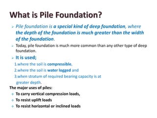
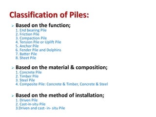


Pile foundations are commonly used when soil conditions require deep foundations, such as with compressible, waterlogged, or deep soils. There are various types of piles classified by function (e.g. end bearing, friction, tension), material (e.g. concrete, timber, steel), and installation method (e.g. driven, cast-in-place). The load carrying capacity of piles can be determined through dynamic formulas, static formulas, load tests, or penetration tests. Factors like pile length, structure characteristics, material availability, loading types, and costs must be considered for proper pile selection.


