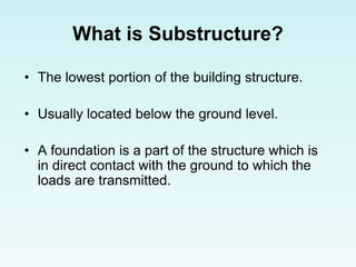
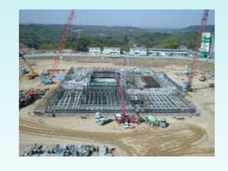
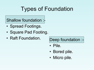
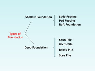
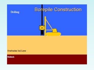
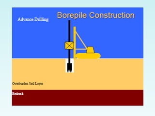
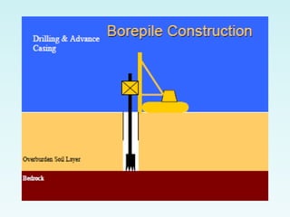
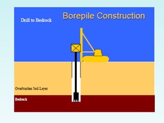
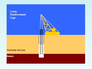
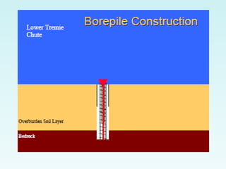
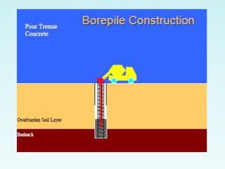
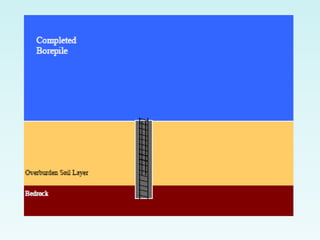
Delhi Call Girls Saket 9711199171 ☎✔👌✔ Full night Service for more than 1 person
substructures ppt.ppt
1. CHAPTER 2 SUBSTRUCTURE
2.1 Introduction
2.2 Building foundation - types and functions
2.3 Deep Foundation
spun pile, micro pile, bakau pile,
bore pile and pile cap
2.4 Shallow Foundation
pad footing, raft foundation,
strip foundation
2.5 Column, stump, ground beam
2. What is Substructure?
• The lowest portion of the building structure.
• Usually located below the ground level.
• A foundation is a part of the structure which is
in direct contact with the ground to which the
loads are transmitted.
3.
4.
5. Main functions of the foundations
• To distribute the load of the structure over
a larger area.
• To transmit the load uniformly under the
structure.
• To provide a firm, level and strong base
over which the superstructure may be
constructed.
6. Main functions of the foundations
• To avoid any settlement or other
movement that can cause damage to any
part of the building (a stable foundation
should bear the loads without sinking or
settling more than an inch at the most).
• To increase the stability of the structure by
preventing its tilting or overturning against
winds, earthquakes and uneven
distribution of live load (Lateral Stability).
8. Type of foundation is selected based
on
• Loading of the building, big load need big
foundation such as raft foundation or piling
• Types of soil such as peat soil prefer piling
or deep foundation
• Economical / financial for number of
building or story – (pad footing or pilling)
9. Type of foundation is selected based
on
• The loads that must be transferred from
the structure to the soil strata supporting it.
This also should evaluate the ability of the
soil to support the ultimate loads.
• The capability of the structure that will
safely transfer the loads from the
superstructure to the foundation bed.
10. Type of foundation is selected based
on
• The possibility and extent of settlement of
the soil due to the presence of mines and
quarries in the vicinity.
• The ability for engineers to fix the depth of
the foundation.
• The ability to determine if the underground
water has sulfates or other salts that can
degrade the foundation materials.
11. Factors That Need To Be Considered
in the Foundation Design
• For more safety precaution use factor of
safety FOS 3
• Increase number of bore hole or suffient
number of borehole so that the result of
the report is more accurate.
– Choose the critical point load for borehole
– Every end of the building
– Supervise the S.I properly make sure no
mistake
12. Factors That Need To Be Considered
in the Foundation Design
• For the safety of the foundation design use
the lowest of bearing capacity value
• The engineer must have good enough
data for the S.I such as previous soil
report, cutting or filling area.
• Engineer also must make sure the original
ground level and purposed level or
formation level while designing the
foundation.
13. Factors That Need To Be Considered
in the Foundation Design
• The correct parameter is important to
prevent from foundation failure that may
occur causing building collapse. It will
cause a big loss of material and even
peoples life.
15. Types of Foundation
Shallow foundation :-
• Spread Footings.
• Square Pad Footing.
• Raft Foundation. Deep foundation :-
• Pile.
• Bored pile.
• Micro pile.
16. Strip Foundation
• This type of foundation is also known as
wall foundation or continues spread
footing foundation.
• It uses is to support load bearing wall.
18. • This type of
footing is
commonly
used to
support the
walls of
above-
ground
circular
storage
tanks
19. Foundations
Definition:
• A foundation is a part of the structure which is in direct contact with
the ground to which the loads are transmitted.
• Every structure, whether big or small, needs a foundation.
• The foundation carries the load of the building and provides it
stability.
20. • The foundation transmits the loads imposed on the structure to the
soil below it and therefore the type of soil used is very important.
• Depending upon whether the soil is stable or loose and unstable
and the type and size of the structure, the foundation is designed as
either shallow or deep.
• A stable foundation should bear the loads without sinking or settling
more than an inch at the most. Even this settlement should be
uniform under the entire building.
21. Construction Terminology
• The foundation is known as the substructure (under the soil
structure) and the building itself is known as the superstructure
(above ground structure).
• We can say that the main function of the foundation is to support
the load of the superstructure and transmit the load evenly to the
soil
22. Main Functions
• To distribute the load of the structure over a larger area.
• To transmit the load uniformly under the structure.
• To provide a firm, level and strong base over which the
superstructure may be constructed.
• To avoid any settlement or other movement that can cause damage
to any part of the building.
23. • To increase the stability of the structure by preventing its tilting
or overturning against winds, earthquakes and uneven
distribution of live load. (Lateral Stability)
26. Heave
Subside
If the forces pushing up is greater
than the forces pushing down the
building will be pushed upwards –
HEAVE
If forces pushing down is greater
than the forces pushing up the
building will sink – SUBSIDENCE
27. Problems if the rules are not
followed
The load spreads at about
400 through the foundation
28. Loads Acting on the Foundation
• The foundation has to bear more than just the load of the
superstructure.
• A load can be defined as anything, which exerts pressure or
thrust on a structure.
• The following are the different types of loads that act on the
building foundation:
• Live Load (Qk) - A live load or imposed load is a movable,
temporary or transferable load. This can include moving vehicles,
people walking or children jumping.
29. Types of loads
• Dead Load (Gk)- This load is permanent and immovable. It is
the non- transferable load of the structure itself.
• Wind Load (Wk) - This load is applicable when the structure is
tall.
• Snow Load - This load is considered when the structure is
situated in snowy, hilly areas.
30. Rock or soil Typical bearing value
(kN/m2)
Massive igneous
bedrock
Sandstone
Shales and mudstone
Gravel, sand and gravel,
compact
Medium dense sand
Loose fine sand
Hard clay
Medium clay
Soft Clay
10,000
2,000 to 4,000
600 to 2,000
600
100 to 300
Less than 100
300 to 600
100 to 300
Less than 75
Typical allowable bearing values
31. Types of Soils
The following are the different types of
soils on which foundations are
constructed:
• Soft soils - This soil is compressible and
yields when loaded. Examples are clayey
soil and loam. Small buildings or ordinary
structures can be built on these types of
soils.
32. • Spreading soils - These are non-cohesive
soils. Examples of this type of soil are sand
and gravel.
• Hard or rocky soils - These are
incompressible and strong soils. They can
withstand heavy loads without yielding.
Multistoried buildings and water reservoirs
are designed on such soils.
33. Bore Pile
Bakau Pile
Shallow Foundation Strip Footing
Types of
Foundation
Deep Foundation
Pad Footing
Micro Pile
Raft Foundation
Spun Pile
34. • The type of foundation used is selected
based on the type of the structure that
has to be built, the type of soil and the
type of material used.
• They are classified into shallow and
deep foundations.
35. Shallow Foundations – for low-rise construction
• When the foundation is placed just below
the superstructure, it is known as shallow
foundation.
• The purpose of these is to transmit the
loads of the superstructure over a wider
area.
• These foundations are suitable for small
buildings.
36. A deep foundation is a type of foundation.
-distinguished from shallow foundations by the
depth they are embedded into the ground.
-the common reasons are because of large design
loads, a poor soil at shallow depth, or site
constraints (like property lines).
-deep foundations including piles, drilled shafts,
caissons, and piers. The naming conventions may
vary between engineering disciplines and firms.
37. -Deep foundations can be made out of timber,
steel, reinforced concrete and pre-tensioned
concrete.
-Deep foundations can be installed by either
driving them into the ground or drilling a shaft and
filling it with concrete, mass or reinforced
38. Spread/Strip Footings
• Also known as footer or simply a footing.
• An enlargement at the bottom of a column or
bearing wall that spreads the applied structural
loads over a sufficiently large soil area.
• Typically, each column and each bearing wall
has its own spread footing.
39. Characteristic of Spread Footings
• Low Cost
• Ease of construction
• For small-medium size structures with
moderate-good soil.
• For large structures with exceptionally
good soil or shallow bedrock.
40.
41. • Spread footing may be built in different
shapes and sizes to accommodate
individual needs.
42. Types of spread footings based on
size and shape
No Types of Spread Footings Applicable
1 Square for a single centrally-located column
2 Rectangular when large moment load are present
3 Circular for light standards, flagpoles etc
4 Continuous for bearing walls
(wall/strip footings)
5 Combined when columns are close together
6 Ring for walls of above-ground circular storage tanks
7 Strap (cantilever footing) when very close to a property line/other structure
43. CONSTRUCTION ACTIVITY ON PAD
FOOTING OR STRIP FOOTING
• PEGGING
• EXCAVATION WORKS
• PROVIDING A MATERIALS
– REBAR
– FORMWORK
– CEMENT
– SAND
– AGGREGATE
• FORMWORK
– EXCAVATE A WORKING SPACES FOR
BETTER CONSTRUCTION
45. Stepped Foundation (Spread Footings)
• This type of foundation is one of the pad
foundation types.
• When the structure is to be constructed on
the hill slopes, this type of foundation is used.
• The foundation trenches are excavated in
steps and each step is filled with some
concrete.
• Each block of concrete is overlapped by the
next block, and so on.
• Square footings usually support a single
centrally-located column.
46. Step no
greater than
450 mm
Overlap to be equal to or
greater than the depth of the
concrete foundation
48. Combined Footing Foundation
• In this type, the two walls or columns of a
superstructure are provided with a single
combined footing.
• This is designed so that the center of gravity of
the supporting area is in proportion to the center
of gravity of the tow column loads.
• These can be rectangular or trapezoidal in
shape.
49. These are usefull
when columns are
located too close
together for each to
have its own footing.
50. Rectangular Spread Footings
• It have plan dimension of B x L, where L is
the longest dimension.
• These are useful when obstructions
prevent construction of a square footing
with a sufficiently large base area and
when large moment loads are present.
51.
52. Circular Spread Footings
• This foundation are round in plan view.
• These are more frequently used as
foundation for light standard, flagpoles,
and power transmission line.
• If these foundation extend to a large
depth, they may be have more like a deep
foundation.
53.
54. Continuous Spread Footings
• This type of foundation is also known as
wall foundation or strip foundation.
• It uses is to support bearing wall.
55. Ring Spread Footings
• This footing are continuous footing that
been wrapped into a circle.
• This type of footing is commonly used to
support the walls of above-ground circular
storage tanks.
57. Raft Foundation
• Also known as Mat Foundation or Floating
Foundation.
• Used where heavily constructed loads are
to be distributed over a large surface area.
• It is used where the soil is marshy, clayey
or soft, with weak bearing capacity.
58. • This consists of reinforced concrete
slabs covering the entire area of
construction, like a floor.
• Always made of reinforced concrete.
59. Consideration of using Raft
Foundation
• The structural loads are so high.
• The soil condition is so poor.
• The bottom of structure is located below
groundwater table.
• Raft foundation are more easier to
waterproof.
60.
61. Conditions for Mat Foundations
-Structural loads require large area to spread
the load
-Soil is erratic and prone to differential
settlements
-Structural loads are erratic
-Unevenly distributed lateral loads
-Uplift loads are larger than spread footings can
accommodate; weight of the mat is a factor
here
-Mat foundations are easier to waterproof
62. Deep Foundation
• In cases where the soil stratum is not
stable or strong, it is necessary to
take the foundation deeper to reach
the stable stratum.
• For instance, in cases of river
bridges, it is important to reach soil
stratum below the scour depth of the
rivers to prevent settlement.
64. Pile Foundation
• Pile foundations are the part of a structure used to carry and transfer
the load of the structure to the bearing ground located at some
depth below ground surface.
• The main components of the foundation are the pile cap and the
piles.
• Piles are long and slender members which transfer the load to
deeper soil or rock of high bearing capacity avoiding shallow soil of
low bearing capacity
• The main types of materials used for piles are wood, steel and
concrete. Piles made from these materials are driven, drilled or
jacked into the ground and connected to pile caps.
• Depending upon type of soil, pile material and load transmitting
characteristic piles are classified accordingly.
65. Function of piles
As with other types of foundations, the purpose of
a pile foundations is:
• to transmit a foundation load to a solid ground
• to resist vertical, lateral and uplift load
• A structure can be founded on piles if the soil
immediately beneath its base does not have
adequate bearing capacity. If the results of site
investigation show that the shallow soil is
unstable and weak or if the magnitude of the
estimated settlement is not acceptable a pile
foundation may become considered. Further, a
cost estimate may indicate that a pile foundation
may be cheaper than any other compared
ground improvement costs.
66. Function of piles
As with other types of foundations, the purpose of
a pile foundations is:
• In the cases of heavy constructions, it is likely
that the bearing capacity of the shallow soil will
not be satisfactory, and the construction should
be built on pile foundations. Piles can also be
used in normal ground conditions to resist
horizontal loads. Piles are a convenient method
of foundation for works over water, such as
jetties or bridge piers.
67. Classification of pile with respect to load
transmission and functional behaviour
• End bearing piles (point bearing piles)
• Friction piles (cohesion piles )
• Combination of friction and cohesion piles
68. End bearing piles
• These piles transfer their load on to a firm
stratum located at a considerable depth below
the base of the structure and they derive most of
their carrying capacity from the penetration
resistance of the soil at the toe of the pile.
• The pile behaves as an ordinary column and
should be designed as such. Even in weak soil a
pile will not fail by buckling and this effect need
only be considered if part of the pile is
unsupported, i.e. if it is in either air or water.
Load is transmitted to the soil through friction or
cohesion.
69. End bearing piles
• But sometimes, the soil surrounding the pile may
adhere to the surface of the pile and causes
"Negative Skin Friction" on the pile. This,
sometimes have considerable effect on the
capacity of the pile. Negative skin friction is
caused by the drainage of the ground water and
consolidation of the soil. The founding depth of
the pile is influenced by the results of the site
investigate on and soil test.
72. Friction piles
• These piles also transfer their
load to the ground through skin
friction.
• The process of driving such piles
does not compact the soil
appreciably.
• These types of pile foundations
are commonly known as floating
pile foundations.
78. Spun Piles vs RC Square Piles
Spun Piles have …
• •Better Bending Resistance
• •Higher Axial Capacity
• •Better Manufacturing Quality
• •Able to Sustain Higher Driving Stresses
• •Higher Tensile Capacity
• •Easier to Check Integrity of Pile
• •Similar cost as RC Square Piles
79. Bored Piles
• Size : 450mm to 2m
• Lengths : Varies
• Structural Capacity : 80Ton to 2,300Tons
• Concrete Grade : 20MPa to 30MPa
(Tremie)
• Joints : None
• Installation Method : Drill then Cast-In-Situ
80. Bored piles
• Bored piles (Replacement piles) are generally
considered to be non-displacement piles a void is formed
by boring or excavation before piles is produced.
• Piles can be produced by casting concrete in the void.
Some soils such as stiff clays are particularly amenable
to the formation of piles in this way, since the bore hole
walls do not requires temporary support except cloth to
the ground surface.
• In unstable ground, such as gravel the ground requires
temporary support from casing or bentonite slurry.
Alternatively the casing may be permanent, but driven
into a hole which is bored as casing is advanced. A
different technique, which is still essentially non-
displacement, is to intrude, a grout or a concrete from an
auger which is rotated into the granular soil, and hence
produced a grouted column of soil.
81.
82.
83.
84.
85.
86.
87.
88.
89.
90.
91.
92. Borepile Cosiderations…
• •Borepile Base Difficult to Clean
• •Bulging / Necking
• •Collapse of Sidewall
• •Dispute on Level of Weathered Rock
93. Micropiles
• Size : 100mm to 350mm Diameter
• Lengths : Varies
• Structural Capacity : 20Ton to 250Ton
• Material : Grade 25MPa to 35MPa Grout
• N80 API Pipe as Reinforcement
• Joints: None
• Installation Method :
–Drill then Cast-In-Situ
–Percussion Then Cast-In-Situ
94.
95. Protecting timber piles from decay:
a) by pre-cast concrete upper section above water level.
b) by extending pile cap below water level
96.
97. Factors to be considered in
selecting a pile type
(timber, steel, concrete or composite)
The applied loads
The required diameter
The required length
(limit: 18m)
The anticipated
driving conditions
The durability of pile
material in specific
environment
The local availability
of each pile type
Factors to be considered in selecting pile type
98.
99. Advantages & Disadvantages
bakau pile
No Advantages Disadvantages
1 Low construction cost Medium axial loads (100 - 400 kN)
2 Used as waterfront structures Susceptible to decay
3 For light driving conditions
Susceptible to damage when
driving
(in loose sands and soft to medium clays)
100. • Damage during driving can be
controlled by:
–Using lightweight hammers
–Using steel bands near butt
–Using a steel shoe on the toe
–Pre-drilling
101. Advantages & Disadvantages
Spun ile
No Advantages Disadvantages
1 Best suited for use as friction piles that Expensive to splice and cut
don't meet refusal during driving
(refusal: pile can't be driven any further, so
it becomes necessary to cut off the portion)
2 Best suited for toe-bearing piles where the Difficult to cut
required length is uniform and predictable
3 Less expensive than steel piles Succeptible to damage during handling
or driving
4 Have a large load capacity Not suited for hard driving conditions
102.
103. Advantages & Disadvantages
Bore Pile
No Advantages Disadvantages
1 Less costs of mobilizing and demobilizing a drill rig Dependent on contractor's skills
2 Less noise and vibration Lower unit end bearing capacity
3 Soils excavated can be observed and classified Expensive for full-scale load test
during drilling
4 Size of shafts can easily be changed during const.
5 Can penetrate soils with cobbles, boulders and
many types of bedrock
6 Possible to support each column with one large
shaft (no pile cap)
105. • Drilling Tools
The helix-shaped flight auger (most common
used)
– Effective in most sols and soft rocks
Augers with hardened teeth and pilot stingers
– Effective in hardpan or moderately hard
rock
Spiral-shaped rooting tools
– Help loosen cobbles and boulders
106. Bucket augers
– To collect cuttings in a cylindrical bucket
– Used in running sands
Belling buckets
– To enlarge the bottom of the shaft (bells or
under reams)
Core barrels
– To cut a circular slot,creating a removable
core
– Used in hard rock
Multi-roller percussion bits
– To cut through hard rock
Cleanout buckets
– To remove final cuttings from hole
107. Drilled Techniques
• Drilling in Firm Soils
– Using dry method (open-hole method)
– Most common used: simple, economy and
good reability
108. • Steps:
– Holes usually advance using conventional
flight auger
– Holes remain open without any special
support
– Check the open hole for cleanliness and
alignment
– Insert steel reinforcing cage
– Pour the concrete
109. • Drilling in Caving (Cave-in) or Squeezing
Soils
– Caving:
• The side of a hole which is collapse before
or during concrete placement.
• Usually in clean sands below the
groundwater table.
110. – Squeezing:
• The sides of hole bulging inward during or after
drilling
• Usually in soft clays and silts or highly organic
soils.
– Most common techniques:
• Using casing
• Drilling fluid (slurry method) using bentonite clay or
attapulgite clay.
111. Pile Cap In the British Standard Code of Practice BS 8004, a
pile cap is defined as a concrete block cast on the head of a
pile, or a group of piles, to transmit the load from the structure
to the pile or group of piles.
Generally, pile cap transfers the load form the structures to a
pile / pile group, then the load further transfers to from soil
External pressures on a pile are likely to be greatest near the
ground surface. Ground stability increases with depth and
pressure. The top of the pile therefore, is more vulnerable to
movement and stress than the base of the pile. Pile caps are
thus incorporated in order to tie the pile heads together so that
individual pile movement and settlement is greatly reduced.
Thus stability of the pile group is greatly increased.
112.
113. Foundations relying on driven piles often have
groups of piles connected by a pile cap (a large
concrete block into which the heads of the piles
are embedded) to distribute loads which are
larger than one pile can bear.
Pile caps and isolated piles are typically
connected with grade beams to tie the
foundation elements together; lighter structural
elements bear on the grade beams while heavier
elements bear directly on the pile cap.
114. Pile cap
• Function:
– To distribute the structural loads to the piles.
– To tie the piles together so they can act as a
unit.
– To laterally stabilise individual piles thus
increasing overall stability of the group
– To provide the necessary combined
resistance to stresses set up by the
superstructure and/or ground movement
115. SUMMARY
• Importance of Preliminary Study
• Understanding the Site Geology
• Carry out Proper Subsurface Investigation
that Suits the Terrain & Subsoil
• Selection of Suitable Pile
• Pile Design Concepts
116. SUMMARY
• Importance of Piling Supervision
• Typical Piling Problems Encountered
• Present Some Case Histories