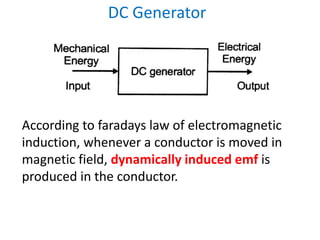
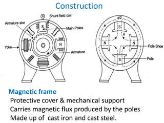
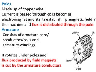
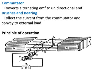
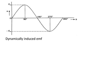
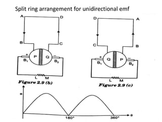
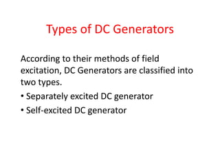
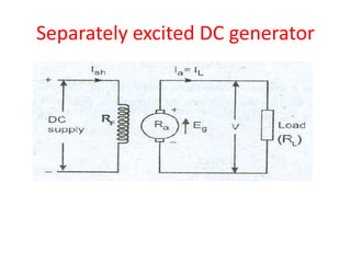
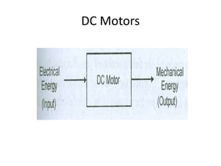
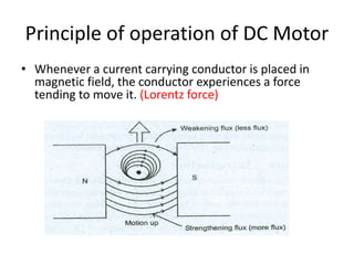
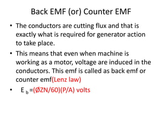
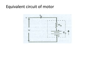
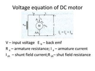
A DC generator converts mechanical energy into electrical energy using electromagnetic induction. It consists of a magnetic frame, field poles, an armature, and a commutator. The armature rotates under the poles, cutting the magnetic flux and inducing an EMF. The commutator converts the alternating EMF into a pulsating DC voltage. DC generators are classified as separately excited, self-excited (series, shunt, compound), depending on how the field is connected. A DC motor operates on the principle that a current-carrying conductor in a magnetic field experiences a torque. It consists of an armature, field poles, a commutator, and brushes. The back EMF opposes the applied voltage
EMF EQUATION OF DC GENERATOR,DC MOTOR|DAY15|BACK EMF,TORQUE OF DC MOTOR|BASIC...Prasant Kumar
#EMF EQUATION OF DC GENERATOR
#EMF EQUATION OF DC MOTOR
#TORQUE EQUATION OF DC MOTOR
# EMF EQUATION OF DC MOTOR IN HINDI
#DERIVATION OF DC MOTOR EMF EQUATION
#FARADAY LAW OF ELECTROMAGNETIC INDUCTION
#back emf in dc motor
#back emf in dc motor in hindi
In this video you will learn about,derivation of dc machine emf equation,back emf,torque equation of dc motor,dc generated,dc motor.To understand electrical machine with trick watch all videos,
MUST UPGRADE YOUR KNOWLEDGE BY FLIPPED LEARNING
#Topic - ELECTRICAL TRANSFORMER
~ Link of all sessions are.
DAY 1 (Need/Definition)
https://youtu.be/BvaykFJ_NoE
DAY 2 (Working principle and Construction)
https://youtu.be/06rgxocihaM
DAY 3 (EMF equation and Turns Ratio)
https://youtu.be/g7e5xBPmv3Y
DAY 4 (Classification of Transformer)
https://youtu.be/6NP5L4MlvY4
DAY 5 ( Ideal and practical transformer on no load)
(Equivalent Transformer)
https://youtu.be/6LCLQC1p3lg
DAY 6 ( Losses in Transformer)
https://youtu.be/ObYNiGgd3hA
DAY 7 (O.C. and S.C. test)
https://youtu.be/8WiJRawHiTce/6LCLQC1p3lg
DAY 8 (Voltage Regulation & Efficiency)
https://youtu.be/6LCLQC1p3lg
DAY 9 (Zero Lecture)
https://youtu.be/N4xWOwgi8I4
DAY 10 (Classification of machine)
https://youtu.be/bmxnU5rC5m4
Construction of Machine
https://youtu.be/34mpphDk3gg
Working Principle of Synchronous Generator & Synchronous Motor
https://youtu.be/bkgf72M8BCY
Working Principle of Induction Motor
https://youtu.be/Lj_iQBoRiK0
DC motors
Torque & Speed Equations
Torque -Armature current Characteristics
Speed - Armature current Characteristics
Torque-speed characteristics
Applications
Speed Control
This presentation describes the per-phase equivalent circuit of induction motor - Power flow diagram - Ratio of air gap power, rotor copper loss and mechanical power developed.
Speed control in 3 phase induction motorKakul Gupta
Speed control in induction motors is required for efficient operation
Various methods of speed control through semiconductor devices:
1. Stator voltage control
2. Stator frequency control
3. Stator voltage control
4. Stator current control
5. Static Rotor Resistance Control
6. Slip Energy Recovery Control
Synchronous generator is a machine which converts mechanical power into electrical power. Three phase synchronous machine are used in thermal , hydro power plant to generate the electrical. Synchronous generator is used to generate the large number of electricity
Saudi Arabia stands as a titan in the global energy landscape, renowned for its abundant oil and gas resources. It's the largest exporter of petroleum and holds some of the world's most significant reserves. Let's delve into the top 10 oil and gas projects shaping Saudi Arabia's energy future in 2024.
We have compiled the most important slides from each speaker's presentation. This year’s compilation, available for free, captures the key insights and contributions shared during the DfMAy 2024 conference.
NUMERICAL SIMULATIONS OF HEAT AND MASS TRANSFER IN CONDENSING HEAT EXCHANGERS...ssuser7dcef0
Power plants release a large amount of water vapor into the
atmosphere through the stack. The flue gas can be a potential
source for obtaining much needed cooling water for a power
plant. If a power plant could recover and reuse a portion of this
moisture, it could reduce its total cooling water intake
requirement. One of the most practical way to recover water
from flue gas is to use a condensing heat exchanger. The power
plant could also recover latent heat due to condensation as well
as sensible heat due to lowering the flue gas exit temperature.
Additionally, harmful acids released from the stack can be
reduced in a condensing heat exchanger by acid condensation. reduced in a condensing heat exchanger by acid condensation.
Condensation of vapors in flue gas is a complicated
phenomenon since heat and mass transfer of water vapor and
various acids simultaneously occur in the presence of noncondensable
gases such as nitrogen and oxygen. Design of a
condenser depends on the knowledge and understanding of the
heat and mass transfer processes. A computer program for
numerical simulations of water (H2O) and sulfuric acid (H2SO4)
condensation in a flue gas condensing heat exchanger was
developed using MATLAB. Governing equations based on
mass and energy balances for the system were derived to
predict variables such as flue gas exit temperature, cooling
water outlet temperature, mole fraction and condensation rates
of water and sulfuric acid vapors. The equations were solved
using an iterative solution technique with calculations of heat
and mass transfer coefficients and physical properties.
Immunizing Image Classifiers Against Localized Adversary Attacksgerogepatton
This paper addresses the vulnerability of deep learning models, particularly convolutional neural networks
(CNN)s, to adversarial attacks and presents a proactive training technique designed to counter them. We
introduce a novel volumization algorithm, which transforms 2D images into 3D volumetric representations.
When combined with 3D convolution and deep curriculum learning optimization (CLO), itsignificantly improves
the immunity of models against localized universal attacks by up to 40%. We evaluate our proposed approach
using contemporary CNN architectures and the modified Canadian Institute for Advanced Research (CIFAR-10
and CIFAR-100) and ImageNet Large Scale Visual Recognition Challenge (ILSVRC12) datasets, showcasing
accuracy improvements over previous techniques. The results indicate that the combination of the volumetric
input and curriculum learning holds significant promise for mitigating adversarial attacks without necessitating
adversary training.
NO1 Uk best vashikaran specialist in delhi vashikaran baba near me online vas...Amil Baba Dawood bangali
Contact with Dawood Bhai Just call on +92322-6382012 and we'll help you. We'll solve all your problems within 12 to 24 hours and with 101% guarantee and with astrology systematic. If you want to take any personal or professional advice then also you can call us on +92322-6382012 , ONLINE LOVE PROBLEM & Other all types of Daily Life Problem's.Then CALL or WHATSAPP us on +92322-6382012 and Get all these problems solutions here by Amil Baba DAWOOD BANGALI
#vashikaranspecialist #astrologer #palmistry #amliyaat #taweez #manpasandshadi #horoscope #spiritual #lovelife #lovespell #marriagespell#aamilbabainpakistan #amilbabainkarachi #powerfullblackmagicspell #kalajadumantarspecialist #realamilbaba #AmilbabainPakistan #astrologerincanada #astrologerindubai #lovespellsmaster #kalajaduspecialist #lovespellsthatwork #aamilbabainlahore#blackmagicformarriage #aamilbaba #kalajadu #kalailam #taweez #wazifaexpert #jadumantar #vashikaranspecialist #astrologer #palmistry #amliyaat #taweez #manpasandshadi #horoscope #spiritual #lovelife #lovespell #marriagespell#aamilbabainpakistan #amilbabainkarachi #powerfullblackmagicspell #kalajadumantarspecialist #realamilbaba #AmilbabainPakistan #astrologerincanada #astrologerindubai #lovespellsmaster #kalajaduspecialist #lovespellsthatwork #aamilbabainlahore #blackmagicforlove #blackmagicformarriage #aamilbaba #kalajadu #kalailam #taweez #wazifaexpert #jadumantar #vashikaranspecialist #astrologer #palmistry #amliyaat #taweez #manpasandshadi #horoscope #spiritual #lovelife #lovespell #marriagespell#aamilbabainpakistan #amilbabainkarachi #powerfullblackmagicspell #kalajadumantarspecialist #realamilbaba #AmilbabainPakistan #astrologerincanada #astrologerindubai #lovespellsmaster #kalajaduspecialist #lovespellsthatwork #aamilbabainlahore #Amilbabainuk #amilbabainspain #amilbabaindubai #Amilbabainnorway #amilbabainkrachi #amilbabainlahore #amilbabaingujranwalan #amilbabainislamabad
Welcome to WIPAC Monthly the magazine brought to you by the LinkedIn Group Water Industry Process Automation & Control.
In this month's edition, along with this month's industry news to celebrate the 13 years since the group was created we have articles including
A case study of the used of Advanced Process Control at the Wastewater Treatment works at Lleida in Spain
A look back on an article on smart wastewater networks in order to see how the industry has measured up in the interim around the adoption of Digital Transformation in the Water Industry.
Hybrid optimization of pumped hydro system and solar- Engr. Abdul-Azeez.pdffxintegritypublishin
Advancements in technology unveil a myriad of electrical and electronic breakthroughs geared towards efficiently harnessing limited resources to meet human energy demands. The optimization of hybrid solar PV panels and pumped hydro energy supply systems plays a pivotal role in utilizing natural resources effectively. This initiative not only benefits humanity but also fosters environmental sustainability. The study investigated the design optimization of these hybrid systems, focusing on understanding solar radiation patterns, identifying geographical influences on solar radiation, formulating a mathematical model for system optimization, and determining the optimal configuration of PV panels and pumped hydro storage. Through a comparative analysis approach and eight weeks of data collection, the study addressed key research questions related to solar radiation patterns and optimal system design. The findings highlighted regions with heightened solar radiation levels, showcasing substantial potential for power generation and emphasizing the system's efficiency. Optimizing system design significantly boosted power generation, promoted renewable energy utilization, and enhanced energy storage capacity. The study underscored the benefits of optimizing hybrid solar PV panels and pumped hydro energy supply systems for sustainable energy usage. Optimizing the design of solar PV panels and pumped hydro energy supply systems as examined across diverse climatic conditions in a developing country, not only enhances power generation but also improves the integration of renewable energy sources and boosts energy storage capacities, particularly beneficial for less economically prosperous regions. Additionally, the study provides valuable insights for advancing energy research in economically viable areas. Recommendations included conducting site-specific assessments, utilizing advanced modeling tools, implementing regular maintenance protocols, and enhancing communication among system components.
Student information management system project report ii.pdfKamal Acharya
Our project explains about the student management. This project mainly explains the various actions related to student details. This project shows some ease in adding, editing and deleting the student details. It also provides a less time consuming process for viewing, adding, editing and deleting the marks of the students.
1. DC Generator
According to faradays law of electromagnetic
induction, whenever a conductor is moved in
magnetic field, dynamically induced emf is
produced in the conductor.
3. Poles
Made up of copper wire.
Current is passed through coils becomes
electromagnet and starts establishing magnetic field in
the machine and flux is distributed through the pole
Armature
Consists of armature core/
conductors/coils and
armature windings
It rotates under poles and
flux produced by field magnets
is cut by the armature conductors.
4. Commutator
Converts alternating emf to unidirectional emf
Brushes and Bearing
Collect the current from the commutator and
convey to external load
Principle of operation
7. E M F induced in a DC Generator
• let Ø be the flux per pole in webers
• let P be the number of poles
• let Z be the total number of conductors in the
armature
• All the Z conductors are not connected in
series. They are divided into groups and let A be
the number of parallel paths into which these
conductors are grouped.
8. • Each parallel path will have Z/A conductors in
series
• Let N be the speed of rotation in revolution
per minute (rpm)
• Consider one conductor on the periphery of
the armature. As this conductor makes one
complete revolution, it cuts PØ webers.
• As the speed is N rpm, the time taken for one
revolution is 60/N sec.
• Since the emf induced in the conductor is
equal to rate of change of flux cut.
9. • e α dØ/dt
= (PØ)/60/N
e = PNØ/60 volts
Since there are Z/A conductors in series in each
parallel path the emf induced
E g = (NPØ/60) (Z/A) volts
E g = (ØZN/60)(P/A) volts
• The armature conductors are generally connected
in two different ways, viz, lap winding and wave
winding. For lap wound armature A=P. In wave
wound machine, A = 2,always
10. Types of DC Generators
According to their methods of field
excitation, DC Generators are classified into
two types.
• Separately excited DC generator
• Self-excited DC generator
12. • I a = I L
• Ra = Resistance of the armature winding
• Terminal Voltage V = E g-Ia R a – V brush
• V brush = voltage drop at the contact of the brush
• Generally V brush is negelected because of very
low value
• Generally emf E g = V+ I a R a + V brush
• Electric power developed = E gIa
• Power delivered to load = VI a
15. • I a = I L = I se
• Generated emf E g = V+ I a R a + I se R se + V brush
Where,
V = terminal voltage in volts
Ia R a = voltage drop in the armature
Ia R se = voltage drop in the series field winding resistance
V brush = brush drop
• Terminal voltage V = E g-Ia R a - I a R se – V brush
• Power developed in the armature = E gIa
• Power delivered to load = VI a orV I L
17. • Terminal voltage V = E g-Ia R a
• Shunt field current Ish =V/ R sh
• Armature current I a = I L + I sh
• Power developed by armature = E gIa
• Power delivered to load = V I L
20. Long shunt compound generator
• Series field current I se = I a= I L + I sh
• Shunt field current Ish = V / R sh
• Generated emf E g = V + I a (R a + R sh) + V brush
• Terminal voltage V = E g – I a(R a+ R sh) – V brush
• Power developed in armature = E g I a
• Power delivered to load = V I L
22. Short shunt compound generator
• Series field current = I se =I L
• Load current = I L
• Armature current I a= I sh + I se
• Generated emf E g = V + I a R a + I se R se + V brush
• Voltage across shunt field winding = Ish R sh
• I sh R sh = E g – I a R a– V brush
= V + I a R a + I se R se + V brush – I a R a–V brush
= V + I se R se
23. Applications of DC Generators
• Shunt generators are used for supplying nearly
constant loads. They are used for battery
charging, for supplying the fields of synchronous
machines and separately excited DC machines
• Since the output voltage of a series generator
increases with load, series generators are ideal
for use as boosters for adding voltage to the
transmission line and to compensate for the line
drop.
• Compound generators maintain better voltage
regulation and hence find use where constancy of
voltage is required.
25. Principle of operation of DC Motor
• Whenever a current carrying conductor is placed in
magnetic field, the conductor experiences a force
tending to move it. (Lorentz force)
26. The direction of motion of conductor is given
by Fleming’s Left hand rule.
27. The magnitude of the force experienced by the
conductor is given by
F= BIL Newtons
Where,
B = magnitude of flux density in Wb/m2
I = current in amperes
L = length of the conductor in meters
28. Back EMF (or) Counter EMF
• The conductors are cutting flux and that is
exactly what is required for generator action
to take place.
• This means that even when machine is
working as a motor, voltage are induced in the
conductors. This emf is called as back emf or
counter emf(Lenz law)
• E b =(ØZN/60)(P/A) volts
30. • The voltage equation of this motor is
V= E b + I a R a
• Form this equation, armature current
I a = (V- E b )/ R a
Where,
V – applied voltage
E b = back emf
I a = armature current
R a = armature current
V - E b = net voltage in the armature circuit
31. Importance of Back EMF
• When DC motor is operating on no load condition,
Therefore the back emf is equal to input voltage and
armature current is small/decreseas.
• When the DC motor is operating on loaded
condition, speed decreases and motor back emf also
decreases. Corresponding armature current
increases.
• When load on the motor decreased, the speed
increases, the back emf also increases causing
armature current to decreases.
Regulates armature current
32. Voltage equation of DC motor
V – input voltage E b – back emf
R a – armature resistance; I a – armature current
I sh – shunt field current;R sh– shut field resistance
33. Voltage equation of DC motor
Here, the current flowing in the armature is
given by
I a = ( V – E b )/ R a
Or
V = E b + I a R a
This equation is known as voltage equation of a
DC motor.
34. Types of DC motors
According to their methods of field excitation,
DC motors are classified into two types.
• Separately excited DC motors
• Self-excited DC motors
. Series motor
. Shunt motor
. Compound motor
* long shunt compound motor
* short shunt compound motor
36. Separately excited DC motor
Armature current I a = line current I L
Back emf E b = V - I a R a – V brush
V brush is very small and therefore it is neglected
38. DC Series Motor
• I a = I L = I se
• The voltage equation is given by
V = E b+ I a R a + I se R se + V brush
I a = I se
V = E b+ I a ( R a + R se ) + V brush
V brush is neglected and hence
V = E b+ I a (R a + R se )
• Ø α I a α I a
43. Long shunt Compound Motor
• I L = I se + I sh
• I se = I a
• I L = I a + I sh
• I sh = V/ R sh
• Voltage equation is given by
V = E b+I a R a + I se R se + V brush
Where I a = I se
V = E b+ I a ( R a + R se ) + V brush
45. Short Shunt Compound Motor
• I L = I se
• I L = I a + I sh
• I L = I se = I a + I sh
• V = E b+Ia R a + Ise R se + V brush
• I se = I L
• V = E b+Ia R a + IL R se + V brush
• Voltage drop across the shunt field winding is = V
- I L = I se
• Vsh = E b+Ia R a + V brush
• I sh = V - IL R se / R sh
48. Torque Equation of a DC Motor
• Torque is nothing but turning or twisting force
about an axis
• Torque is measured by the product of force
and radius at which the force acts.
49. • The angular velocity of the wheel is
ω= (2ΠN)/60 rad/sec
Torque T = F × r (N-m)
Workdone per revolution = F × distance moved
= F × 2 Π r joules
Power developed P = workdone / time
= (F × 2 Π r)/time for 1 rev
= (F × 2 Π r)/(60/N)
(rpm = 60 ; rps = 60/N ; time for 1 rev = 60/N
P = (F × r) (2ΠN)/60
P = T ω watts
Where T = torque in N-m , ω = angular speed in rad/sec
50. • The gross mechanical power developed in the
armature is E b I a
• Then power in armature = armature torque × ω
E b Ia = Ta × (2ΠN)60
E b = PØZN/60A
PØZN/(60A) I a = Ta × (2ΠN)60
Ta = (Ø I a PZ)/ 2ΠA
Ta = (0.159Ø I a )(PZ/A) N-M
The above equation is torque equation of a DC motor.
Torque is proportional to the product of the armature
current and the flux
51. Speed control of DC shunt motor
For a Dc motor, the speed equation is obtained as follows
E b = V - I a R a
E b = PØZN/60A
V - I a R a = PØZN/60A
N = (V - I a R a )60A/ PØZ
Since for a given machine , Z,A and P are constants
N = K(V - I a R a )/Ø
Where K is a constant.
Speed equation becomes N α E b /Ø
Hence speed of the motor is directly proportional to back emf
and inversely proportional to flux. By varying flux and
voltage, the motor speed can be changed.
54. Speed control of DC series motor
1. Variable resistance in series with motor
55. 2. Flux control method
Field diverter Armature diverter
Tapped field control
56. For DC Shunt motor torque is directly proportional to
the armature current. For Dc series motor, the series field
current is equal to the armature current Ia
φ α Ia
HenceT α Ia α I2
a
For DC series motor, the torque is directly proportional to the
square of the armature current. The speed and torque
equations are mainly used for analyzing the various
characteristics of DC motors.
57. Applications of DC Motors
• DC shunt motor are used where speed has to maintain
nearly constant with load and where a high starting
torque is not required. Thus shunt motors may be used
for driving centrifugal pumps and light machine tools,
wood working machines, lathe etc.,
• Series motors are used where the load is directly
attached to the shaft or through a gear arrangements
and where there is no danger of load being “thrown
off”. Series motors are ideal for use in electric trains,
where the self-weight of the train acts as load and for
cranes, hoists, fans, blowers,converyers,lifts etc. where
starting torque requirement is high.
58. Applications of DC Motors
• Compound motors are used for driving heavy
machine tools for intermittent loads shears,
punching machines etc.,
69. Cooling arrangement in Transformers
• The various methods of cooling employed in a
transformer are
1. Oil immersed natural cooled transformers
2. Oil immersed forced air cooled transformers
3. Oil immersed water cooled transformers
4. Oil immersed forced oil cooled transformers
5. Air blast transformers
70.
71. EMF Equation of a Transformer
• N1 – Number of primary turns
• N2 – Number of secondary turns
72.
73.
74. We know that T= 1/f, where f is the frequency in Hz
Average rate of change of flux = φm/(1/4f) wb/seconds
If we assume single turn coil, then according to Faradays
law of electromagnetic induction, the average value of
emf induced/turn = 4 f φm volt
Form factor = RMS Value/ Average Value
= 1.11 (since φm is sinusoidal)
RMS value = Form Factor × Average Value
RMS Value of emf induced/turn = (1.11)×(4 f φm )
= 4.44 f φm volts
75. RMS value of emf induced in the entire
primary winding E1 = 4.44 f φm × N1
E1 = 4.44 f Bm A × N1 Volts
Similarly RMS value of emf induced in the
secondary E2 = 4.44 f Bm A × N2 Volts
76. Transformation Ratio (K)
For an ideal transformer
V1 = E1 ; V1 = E2;
V1I1 = V2I2
V2/V1 = I1/I2; E2/E1 = I1/I2
From transformer emf induced equation
E2/E1 = N1/N2
We have E2/E1 = N1/N2 = I1/I2= K
Where K is the transformation ratio.
If N2>N1 i.e. K>1, then transformer is a step up transformer.
If N2<N1 i.e. K<1, then transformer is a step down transformer
Voltage ratio = E2/E1 = K
Current ratio = I2/I1= 1/K
77. Ideal Transformer
The ideal transformer has the following
properties
• No winding resistance. i.e., purely inductive.
• No magnetic leakage flux.
• No I2 R loss i.e., no copper loss.
• No core loss.
78. Ideal Transformer
An ideal transformer consists of purely inductive
coil(winding) and loss free core. Windings are
wound on a core. It is shown in figure.
81. Rating of a Transformer
• Voltage rating
• Current rating
• Power rating
Why transformer rating in kVA?
82. Applications of Transformer
• Used in transmission and distribution
• Used as an instrument transformer for
measuring current (C.T) and measuring
voltage (P.T)
• Used as a step down and step up transformer
to get reduced or increased output voltage
• Radio and TV circuits, telephone circuits,
control and instrumentation circuits
• Furnaces and welding transformer
83. Single phase induction motor
These motors used in
• Homes
• Offices
• Shops
• Factories
They provide motive power for
• Fans
• Washing machines
• Hand tools like drillers, record player, refrigerator,
juice makers etc
84. Single phase induction motor
The single phase induction motor are simple
in construction. The main disadvantage of
these motors are
• Lack of starting torque
• Reduced power factor
• Low efficiency
87. Starting of single phase induction motor
• From the principle of operation, the single
phase induction motor has no self starting
torque. This can be explained in two ways
1. Two field (or) double field revolving theory
2. Cross field theory.
89. Double field revolving theory
Resultant flux would be 2× (φm/2)sinθ = φmsinθ
The resultant flux now is zero
90. Double field revolving theory
After half cycle, fluxes a and b will have resultant
of -2×(φm/2)= -φm
91. Double field revolving theory
After three quarters of cycle, again the resultant
is zero as shown.
92. Double field revolving theory
So the flux variation is φm , 0, -φm , 0. this flux
variation with respect to θ is plotted which is
shown below
93. Double field revolving theory
The slip of the rotor with respect to the forward
rotating flux is given by
S f = (Ns – N)/ Ns
The slip of the rotor with respect to the backward
rotating flux is given by
S b = (Ns – (-N))/ Ns
= 1 + (N/ Ns)
= 1 + 1-s
= 2-s
94. Double field revolving theory
Due to two more fluxes tow more torques
forward and backward torques and are
oppositely directed so that the net torque is
equal to their differences as shown
95. Operation of single phase induction motor
Due to the transformer action, currents are
induced in the rotor conductors. The direction
of the current is to oppose the stator mmf.
97. Types of single phase induction motor
The single phase induction motors can be
classified according to the phase difference
produced between the currents in the main
and auxiliary windings.
1. Split- phase motors
2. Capacitor-start motors
3. Capacitor-run motors
4. Capacitor-start and –run motors
5. Shaded-pole motors
100. Split phase induction motor
Applications:
It is mainly used for loads that require low and
medium torque. The applications are
• Fans
• Blowers
• Centrifugal pumps
• Washing machines
101. Split phase induction motor
characteristics
• The percentage of rated starting torque is
100% to 250%
• The break down torque is upto 300%
• The power factor of this motor is 0.5 to 0.65
• The efficiency of the motor is 55% to 65%
• The power rating of this motor is in the range
of ½ to 1HP.
104. Capacitor start single phase induction motor
Applications:
It is mainly used for hard starting loads, such as
1. Compressors
2. Pumps
3. Conveyors
4. Refrigerators
5. Air conditioning equipments
6. Washing machines
105. Capacitor start single phase induction motor
characteristics
• The percentage of rated starting torque is
250% to 400%
• The breakdown torque is upto 350%
• Power factor of the motor is 0.5 to 0.65
• The power rating of the motor is 1/8 to 1HP
• The efficiency of the motor is 55% to 65%
108. Capacitor run single phase induction motor
The main advantages of these motors are
• High power factor at full load
• High full-load efficiency
• Increased pull-out torque
• Low full-load line current
It is mainly used in low noise applications such as
• Fans
• Blowers
• Centrifugal pumps
109. Capacitor run single phase induction motor
The characteristics of these motors are
112. Capacitor start capacitor run motor
The main advantages of these motors are
• High starting torque
• High efficiency
• High power factor
113. Capacitor start capacitor run motor
It is mainly used for low noise and high starting
torque applications such as
• Compressors
• Pumps
• Conveyors
• Refrigerators
118. Shaded pole motor
The main disadvantages of these motors are
• Low efficiency
• Low power factor
• Very Low starting torque
119. Shaded pole motor
The main applications of these motors are for
loads requiring low starting torque such as
• Fans
• Blowers
• Turn tables
• Hair driers
• Motion picture projectors