This document provides an overview of alternating current (AC) circuits. It discusses the characteristics of AC voltage and current, and how resistors, inductors, and capacitors behave in AC circuits. Key points include:
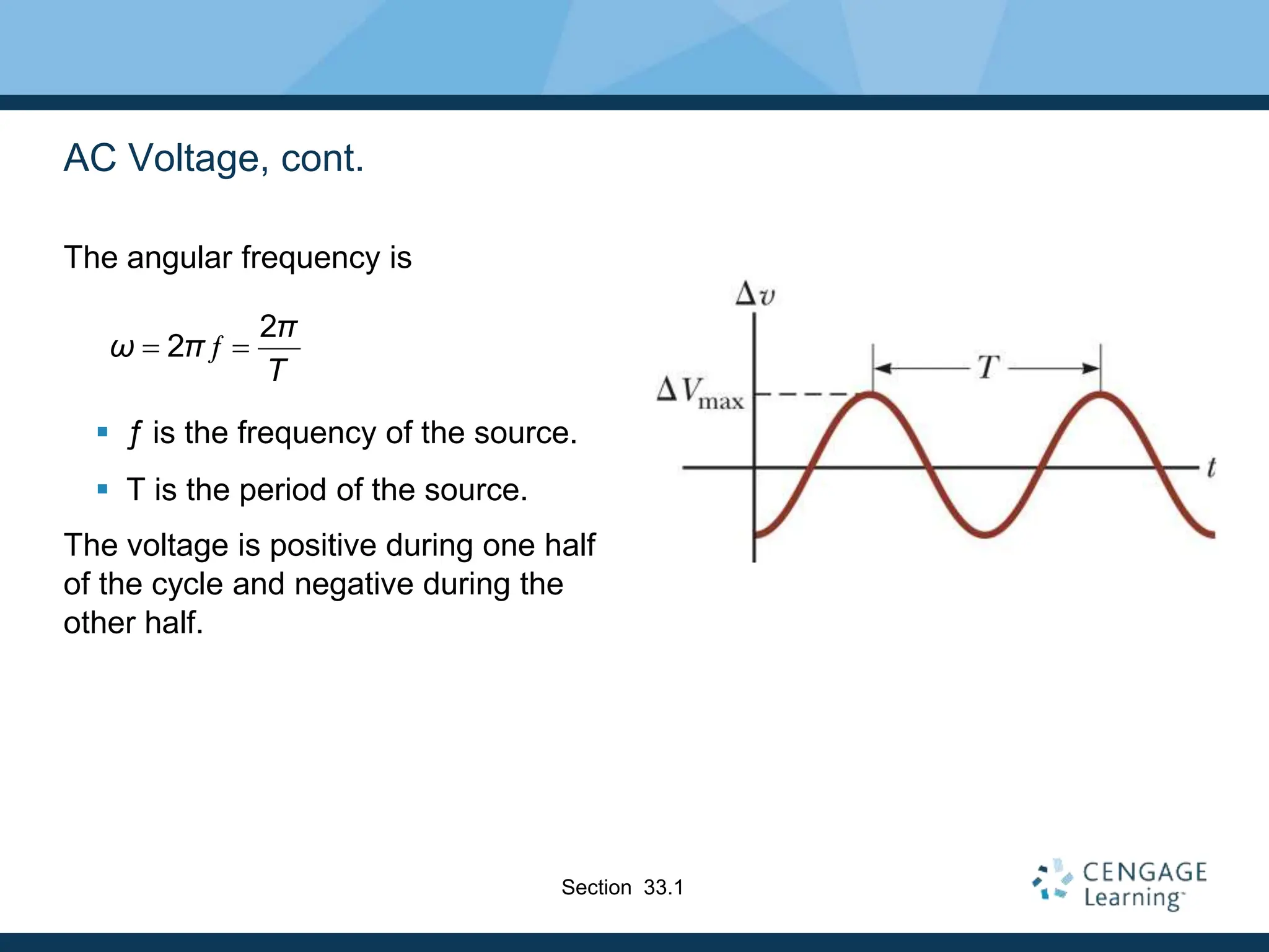
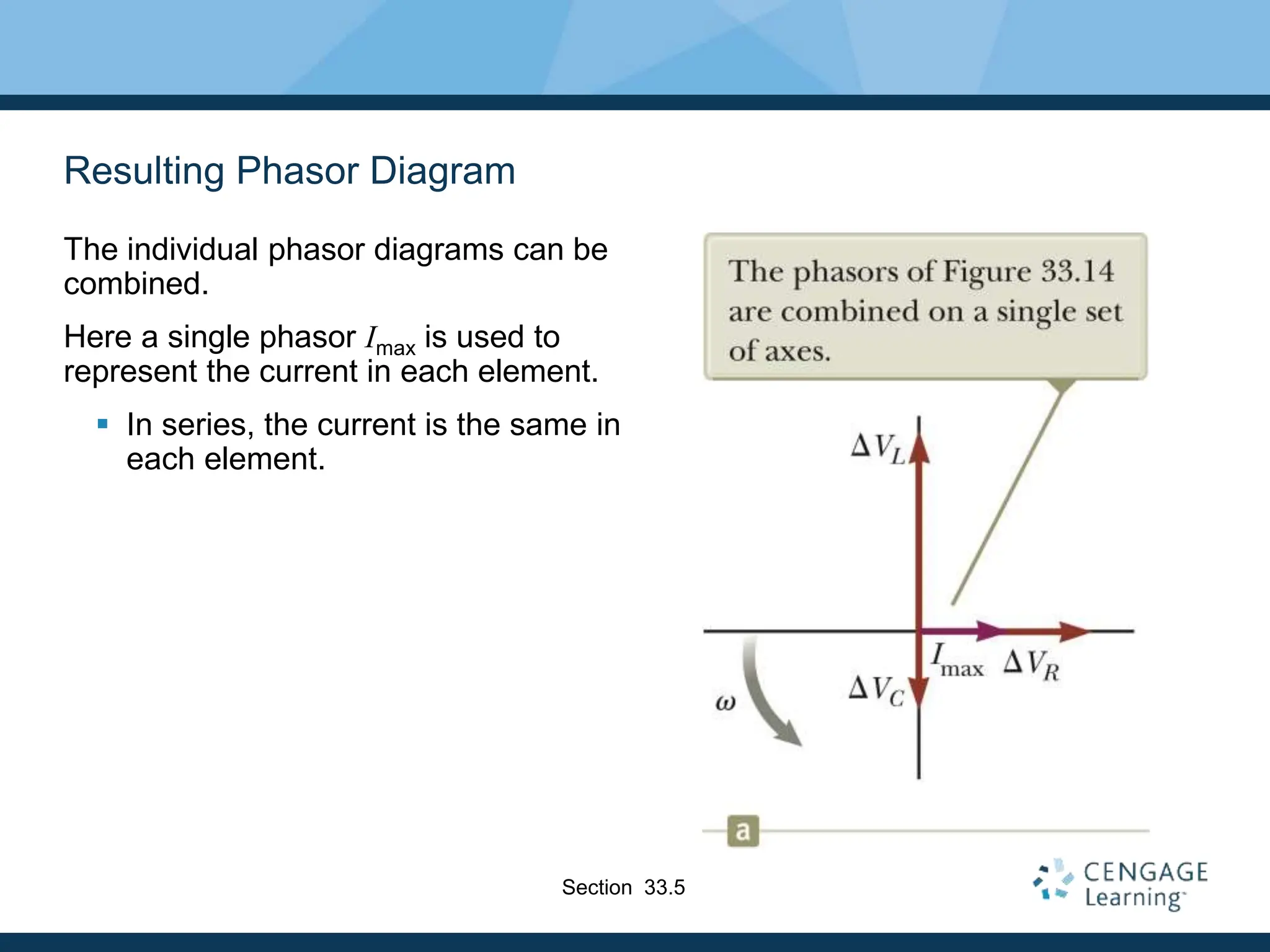
- AC voltage and current vary sinusoidally with time and can be represented using phasors.
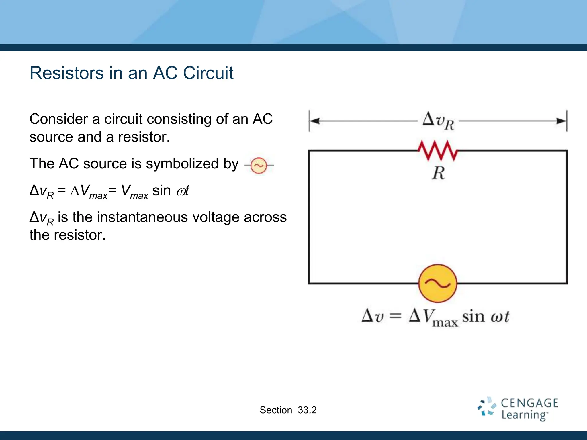
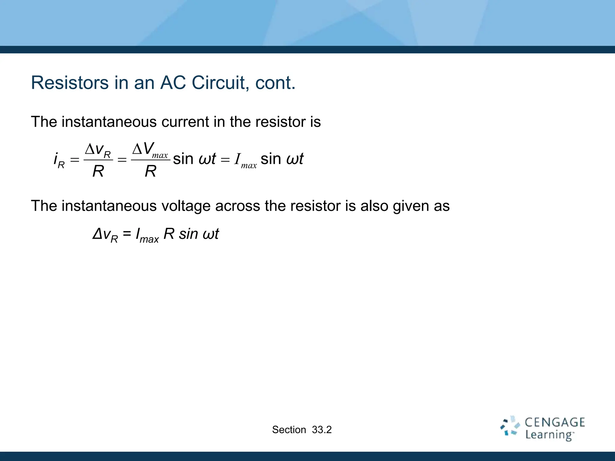
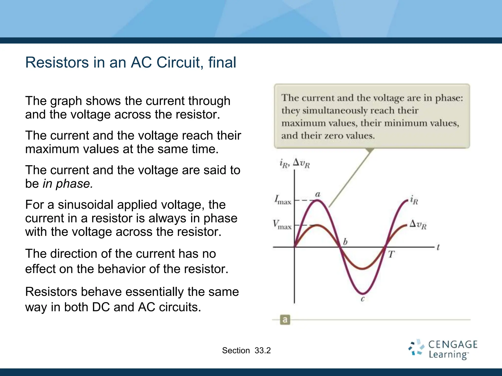
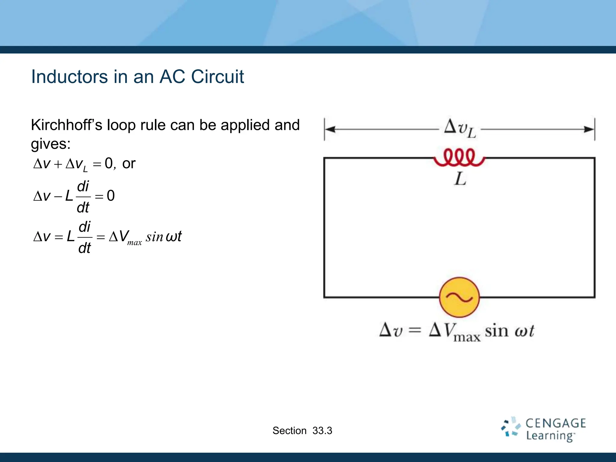
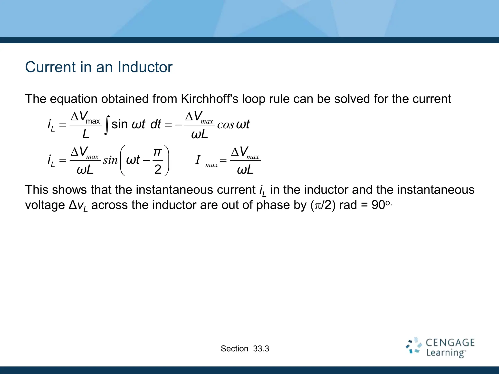
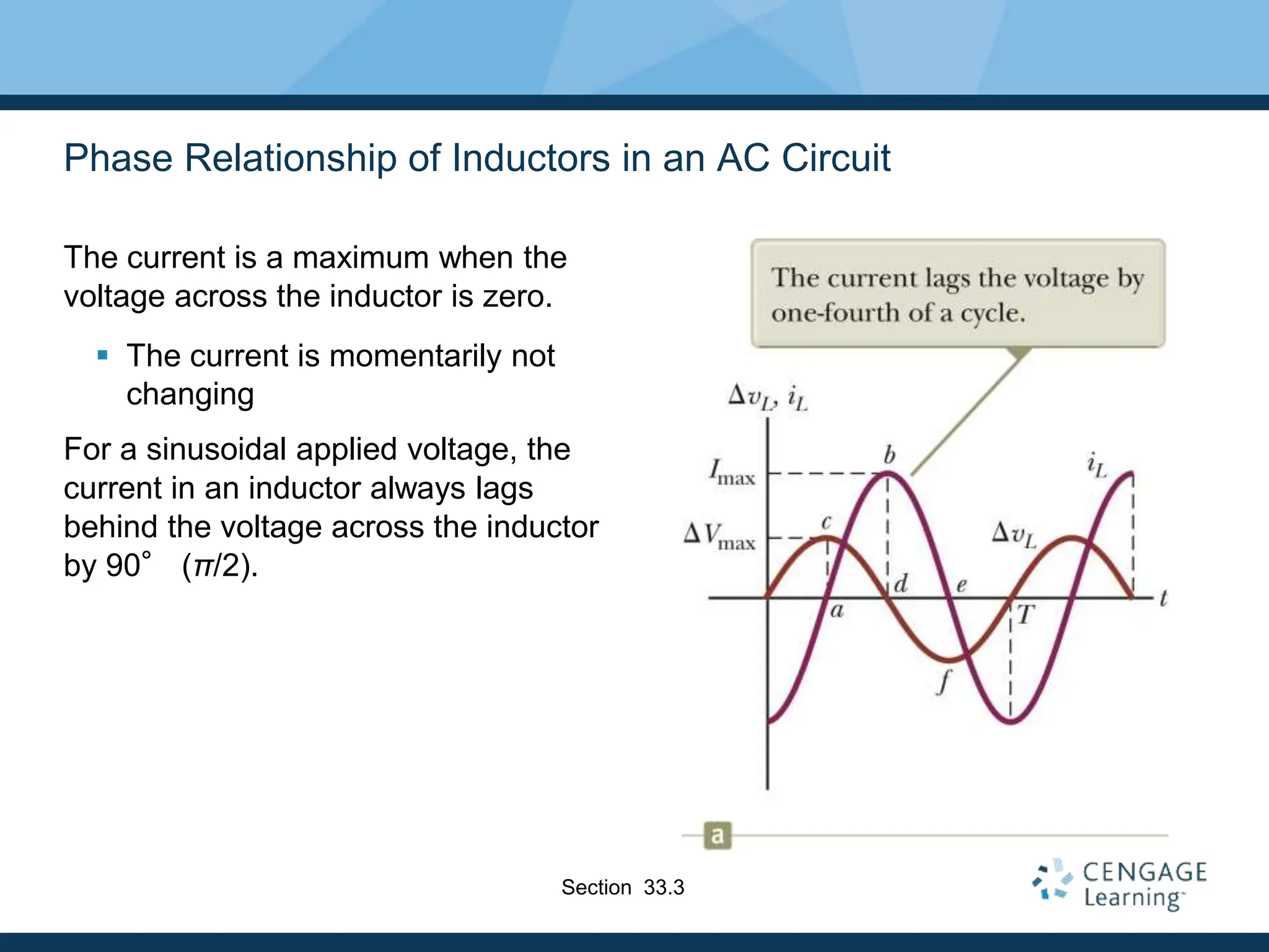
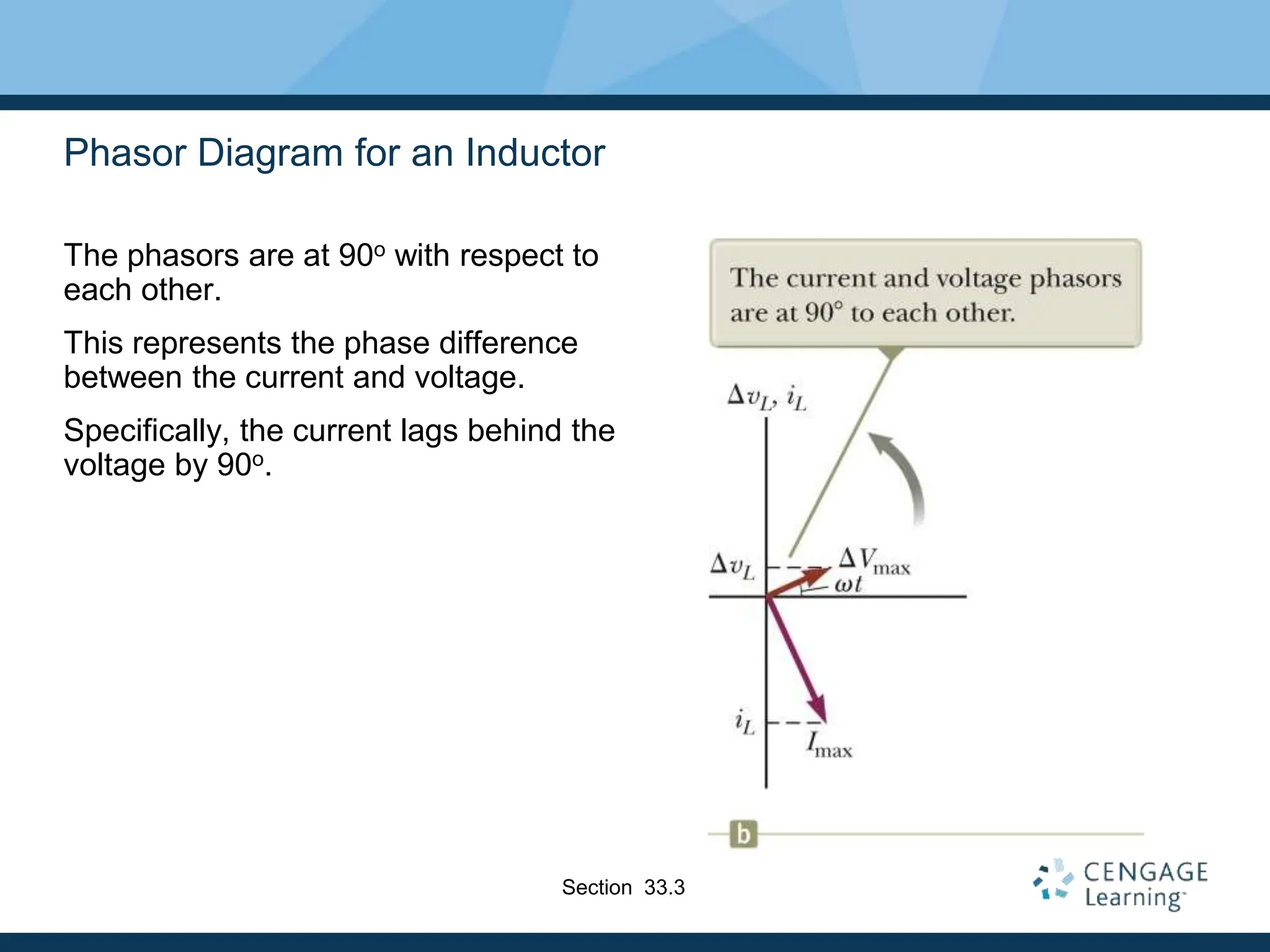
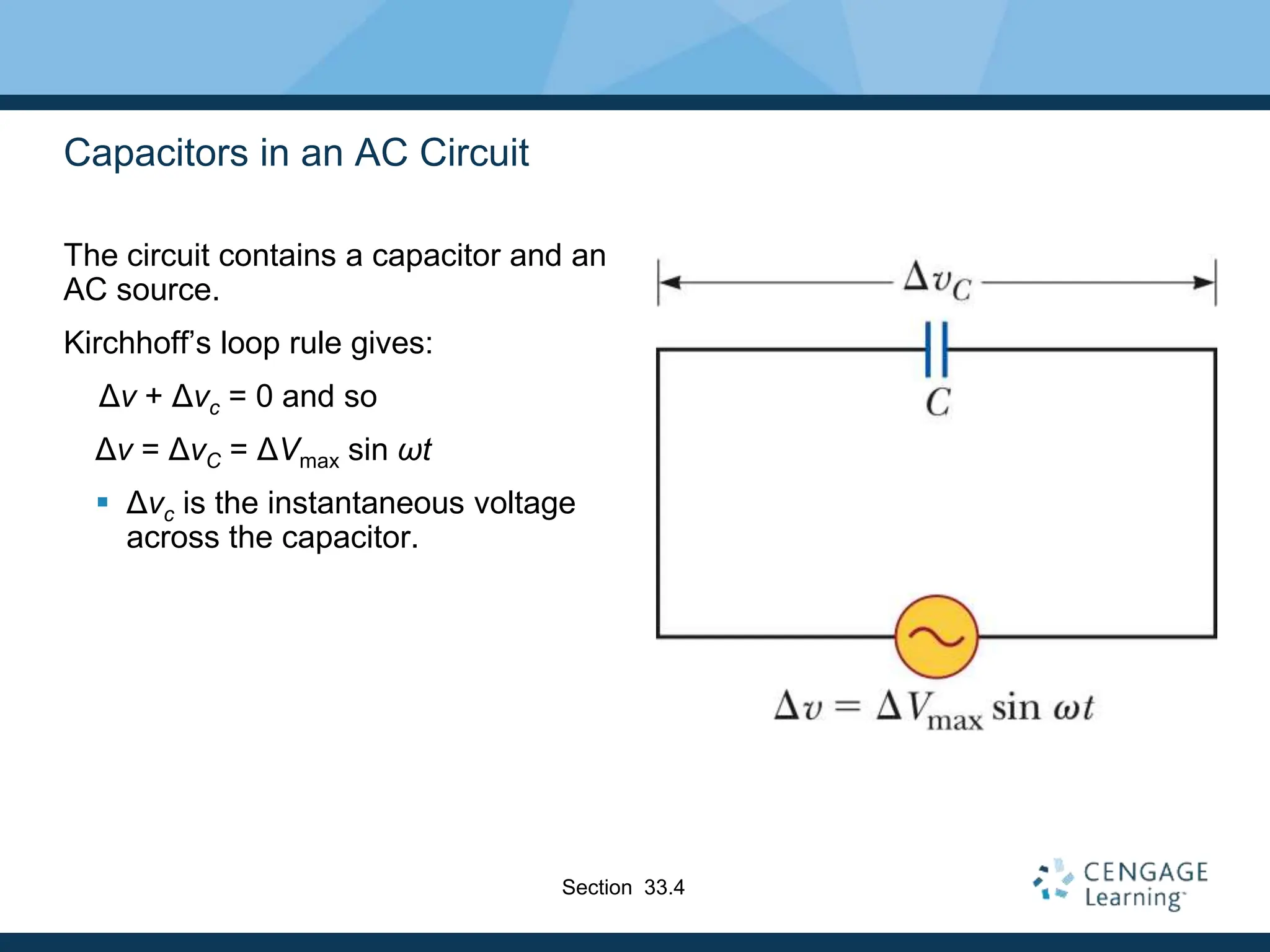
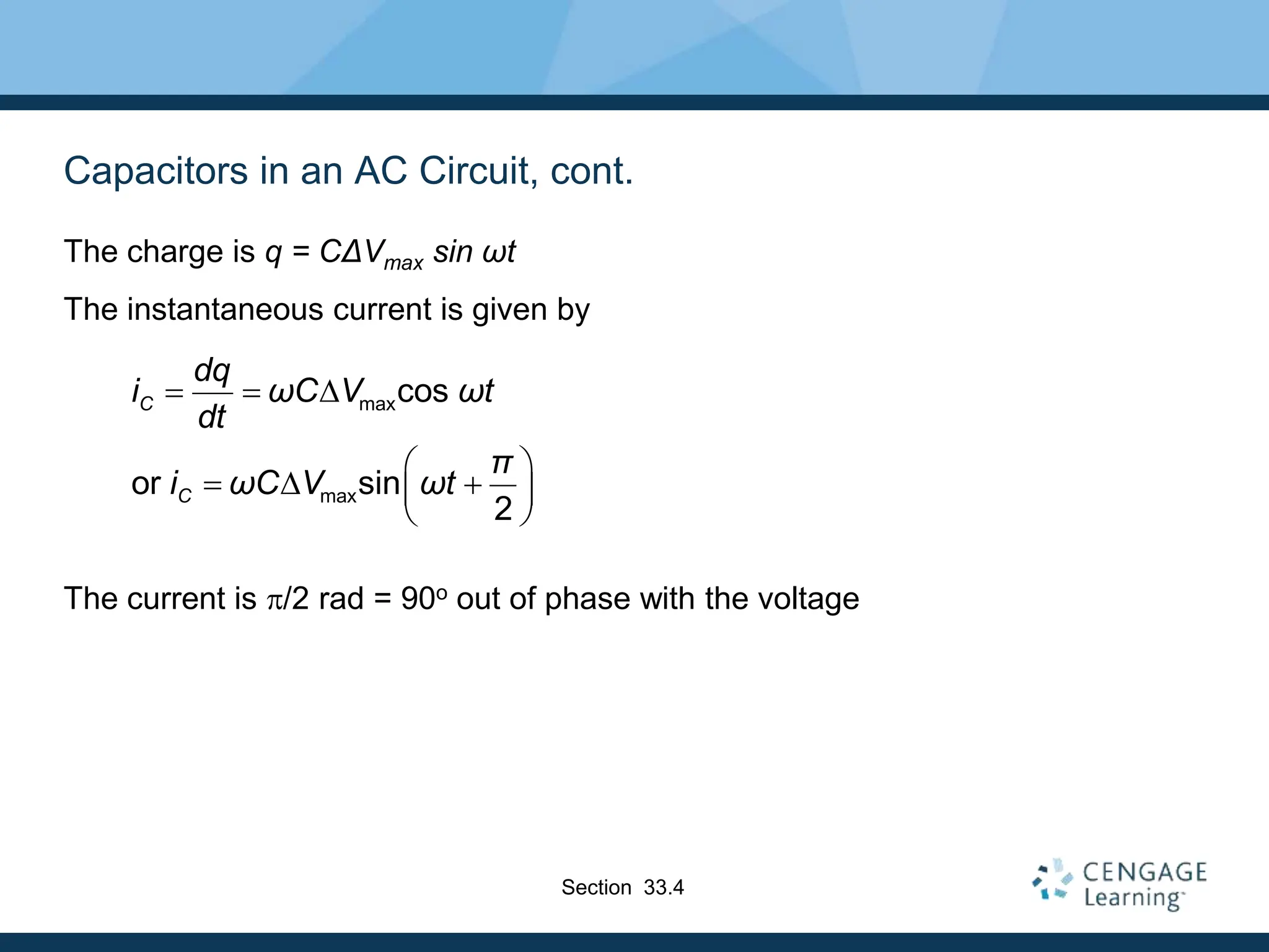
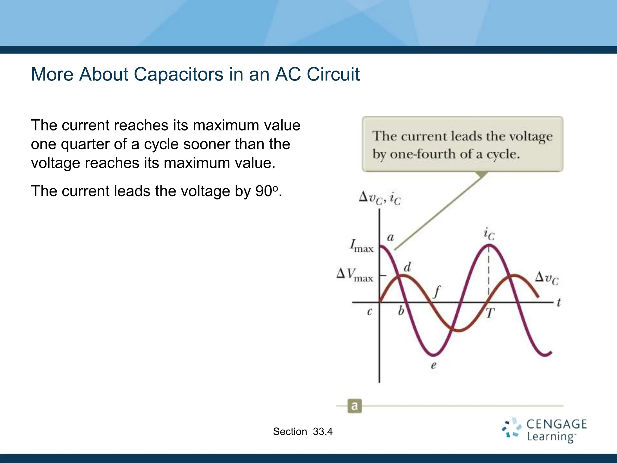
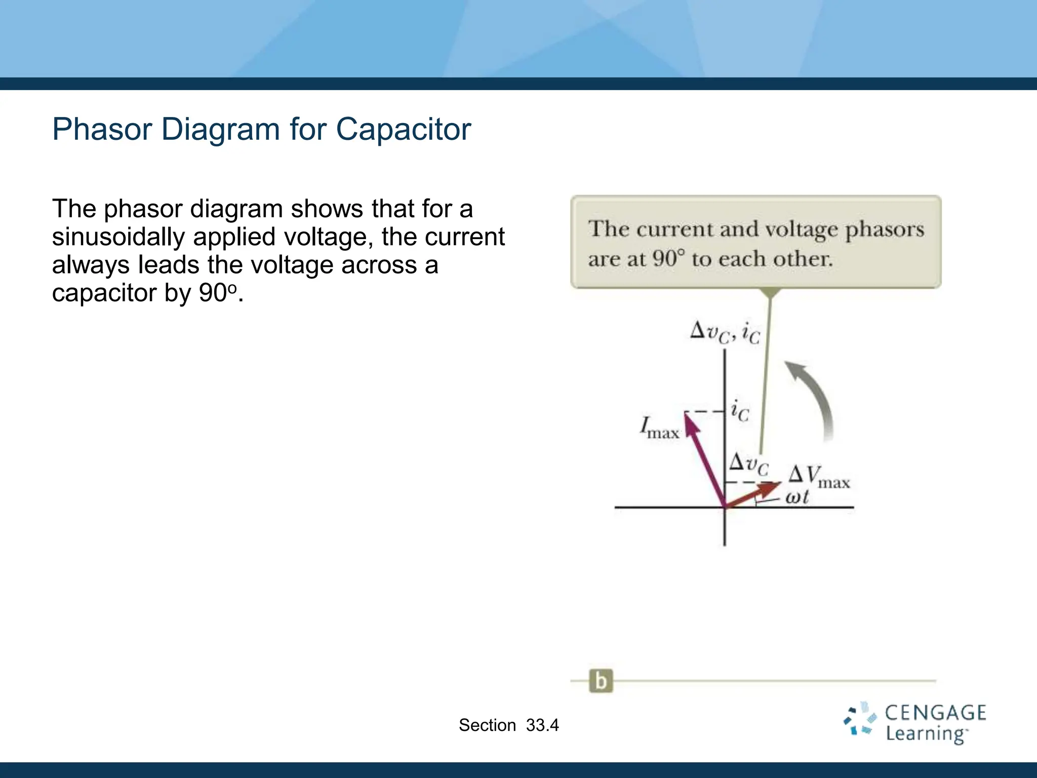
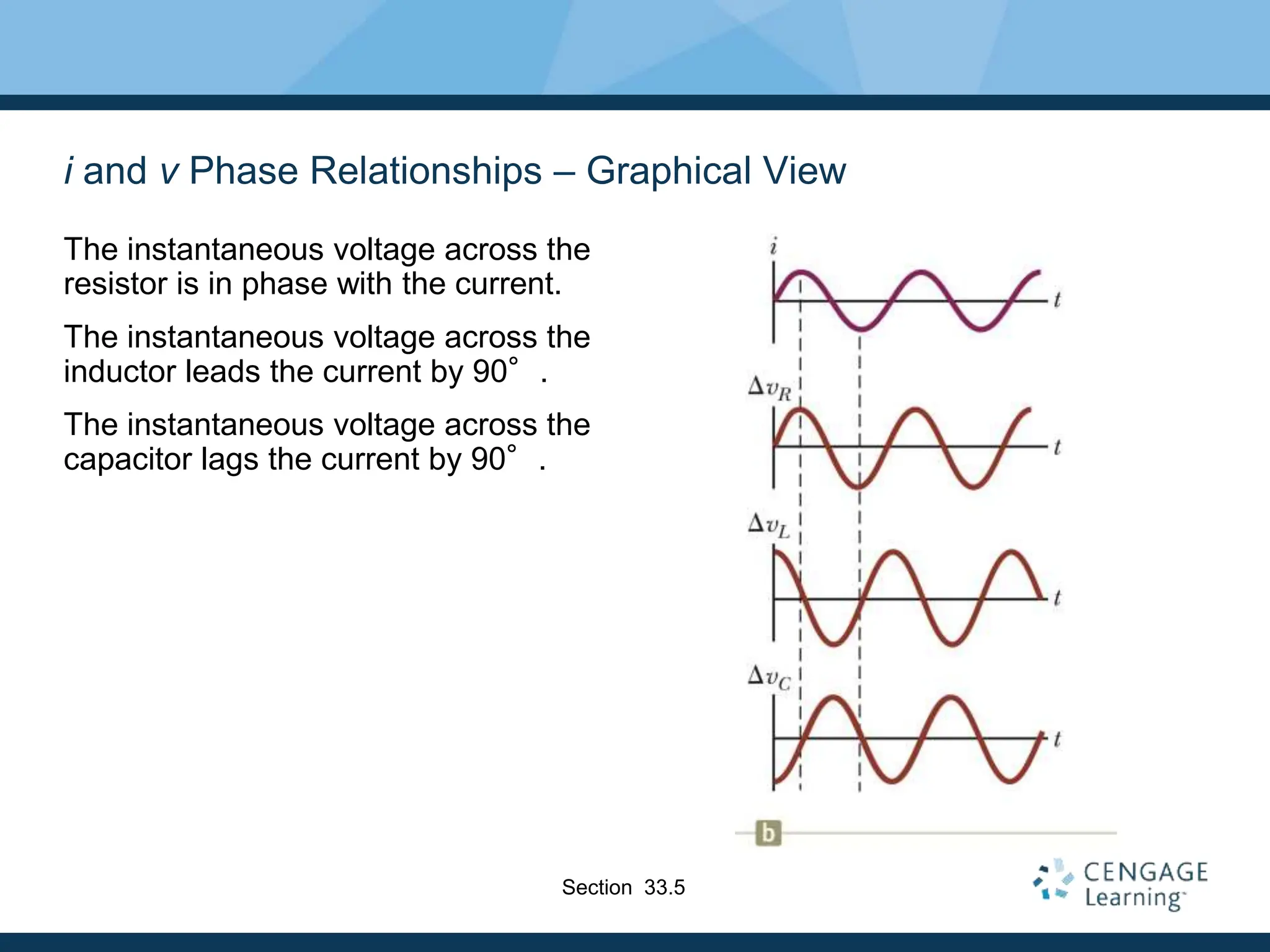
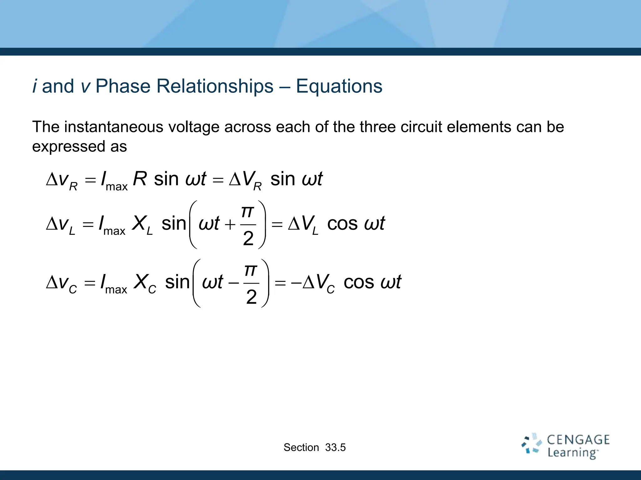
- Resistors are in phase with voltage, inductors cause current to lag 90° behind voltage, and capacitors cause current to lead 90° ahead of voltage.
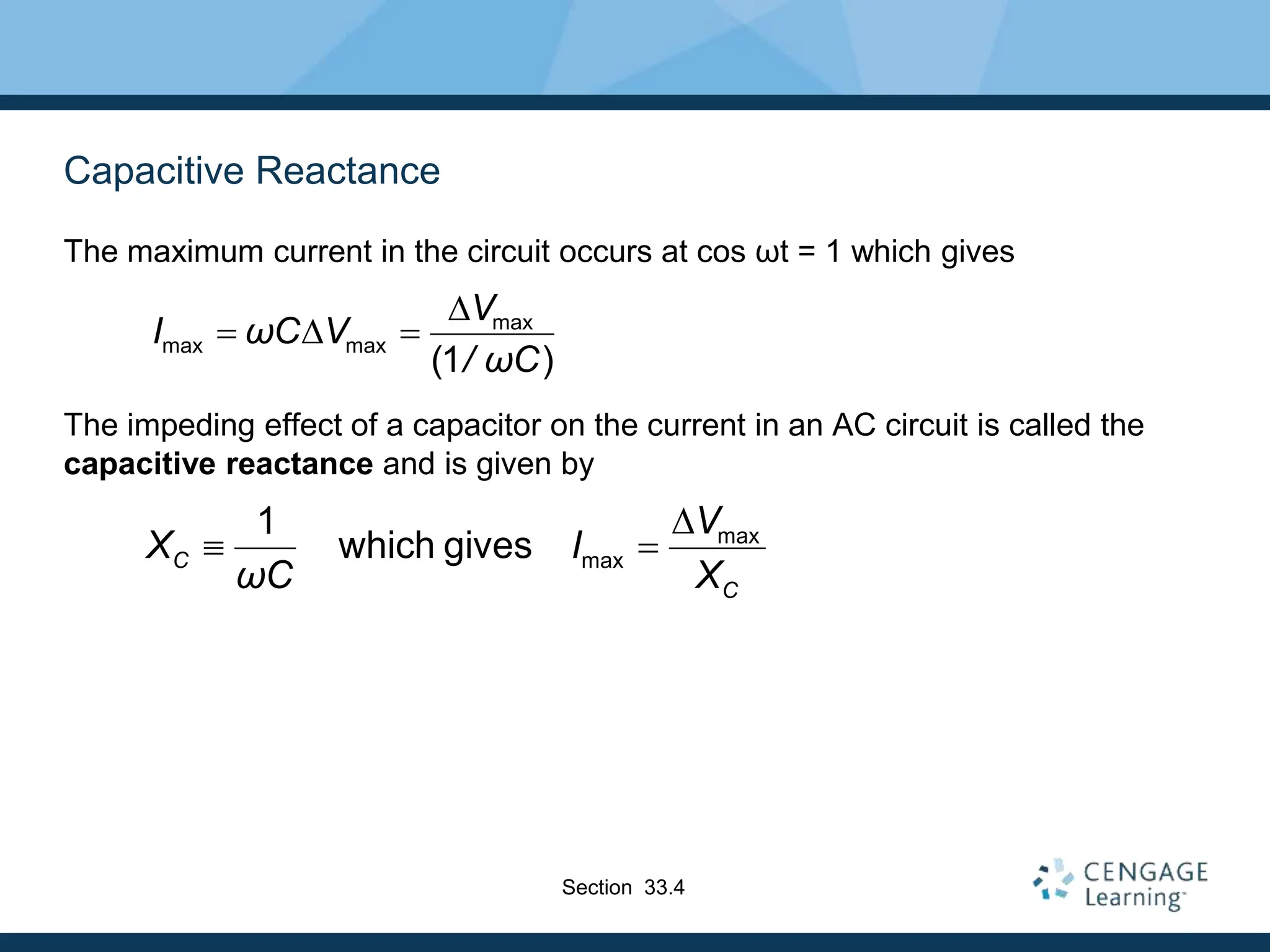
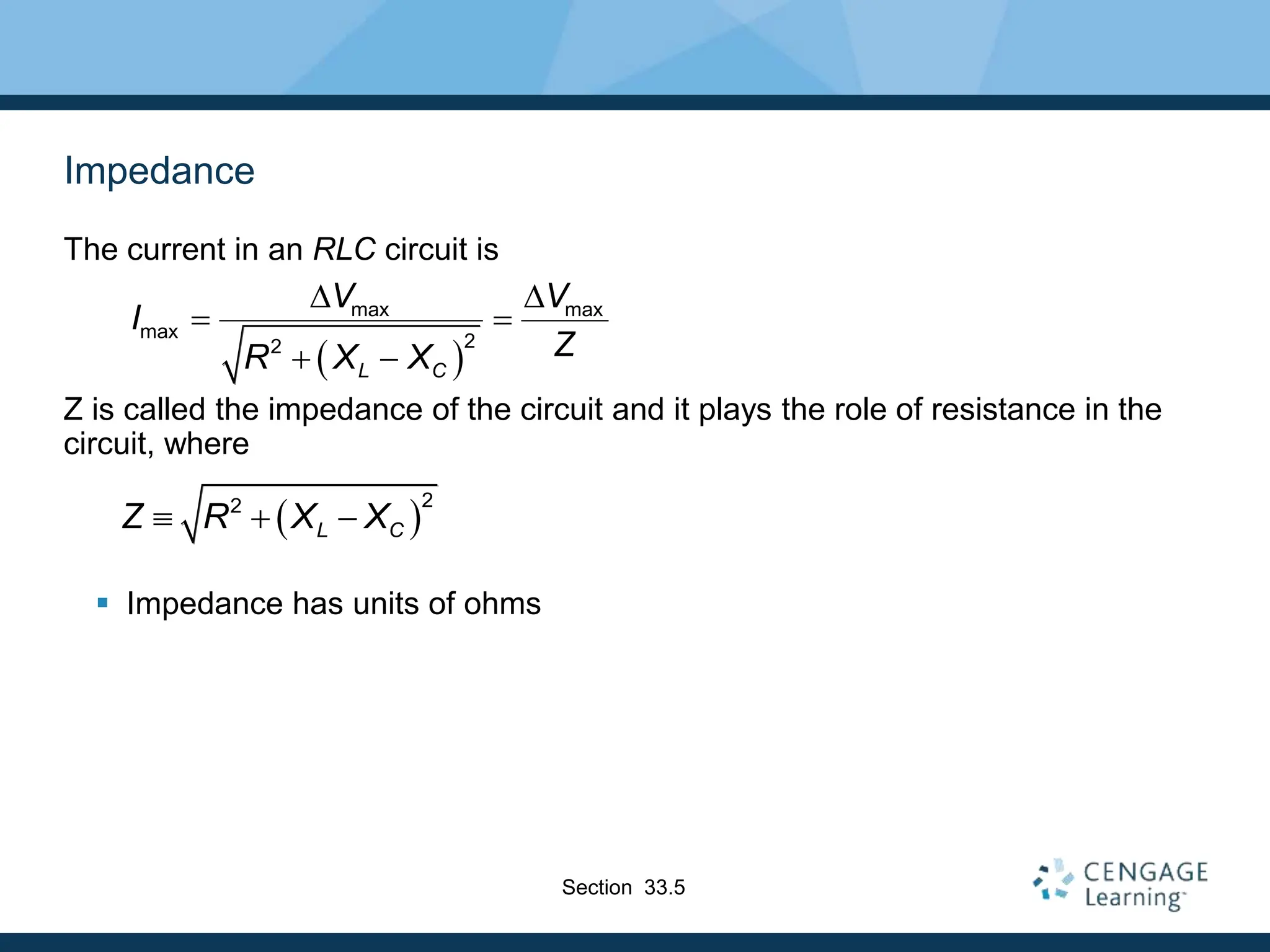
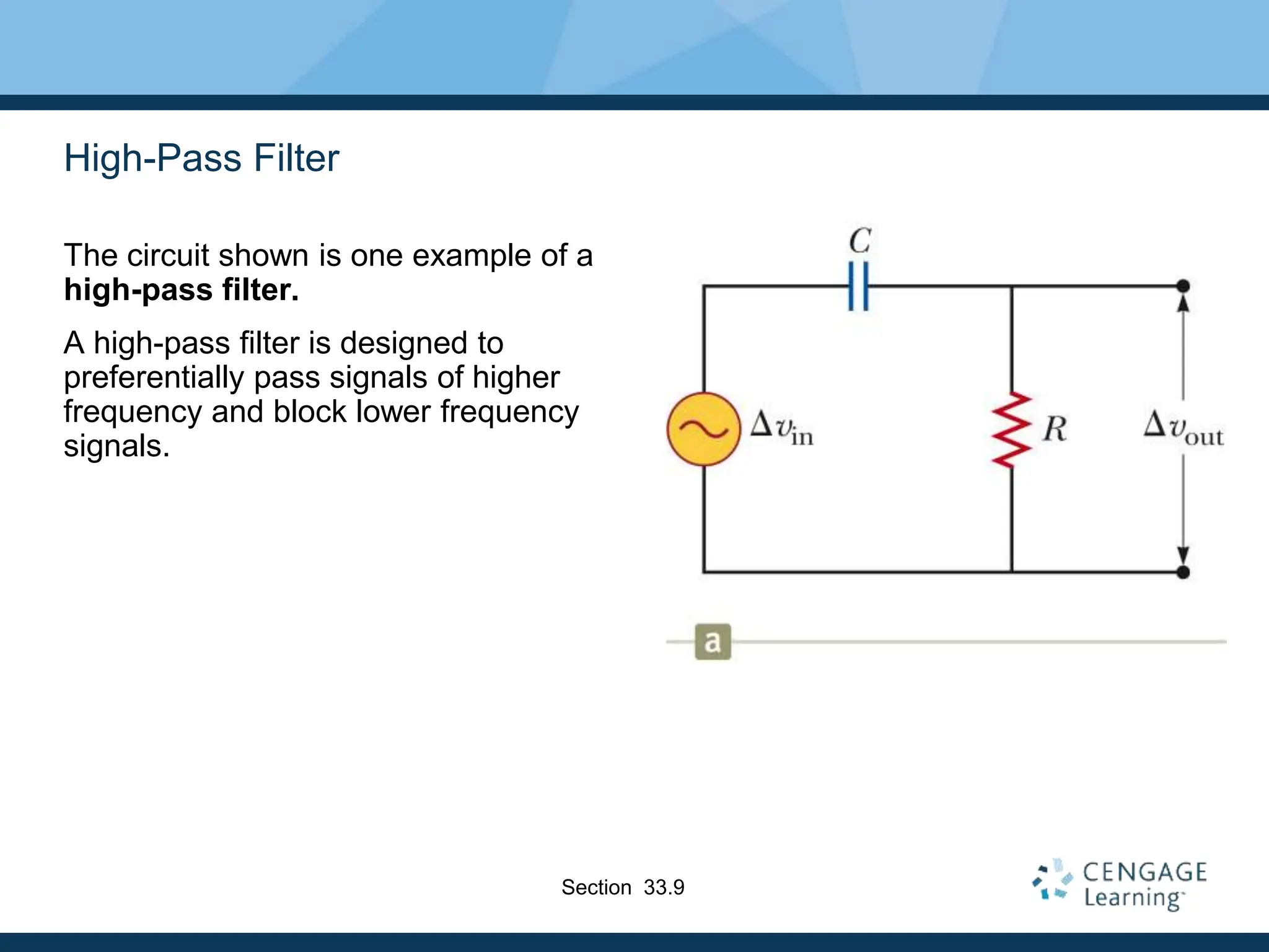
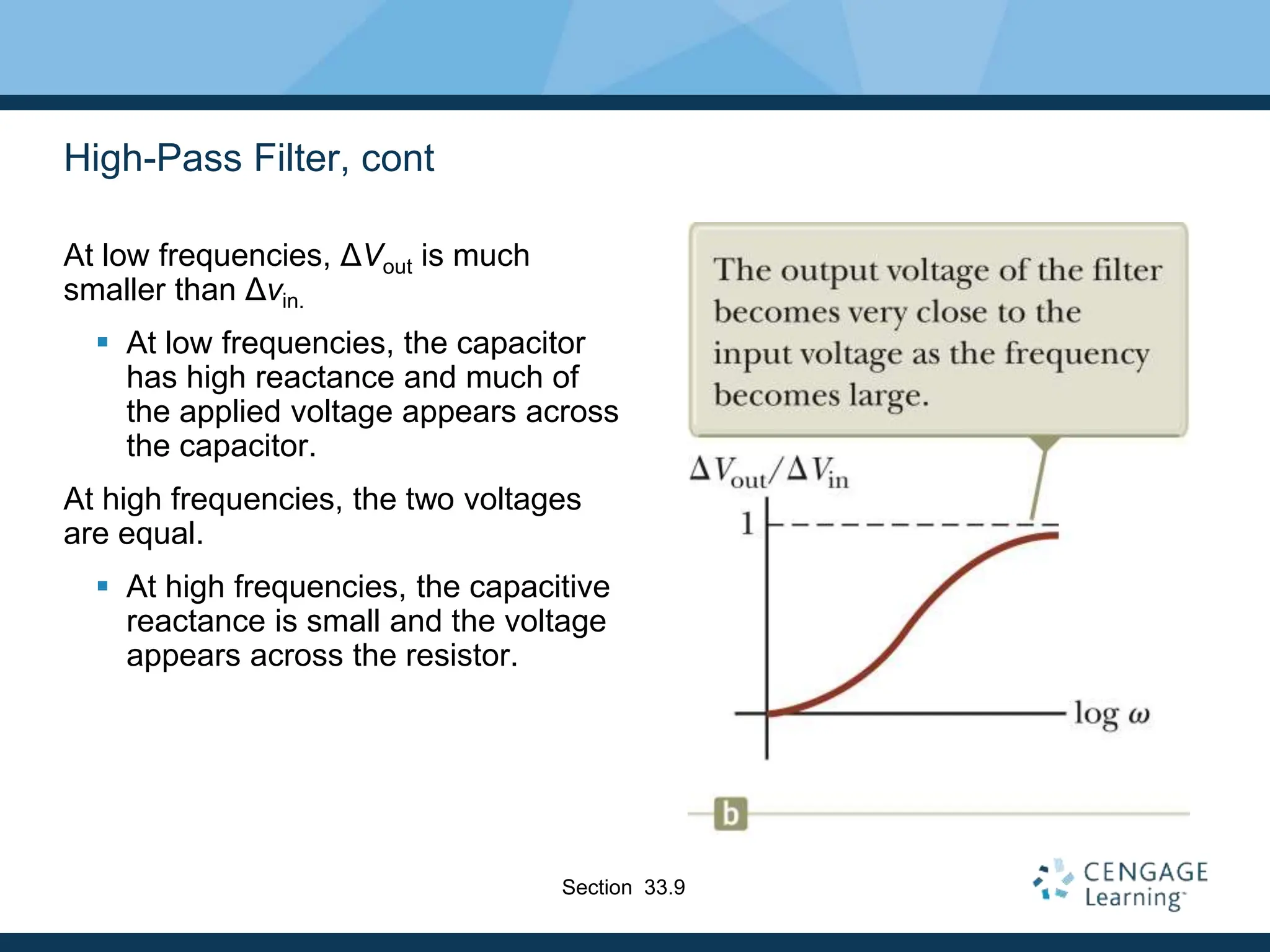
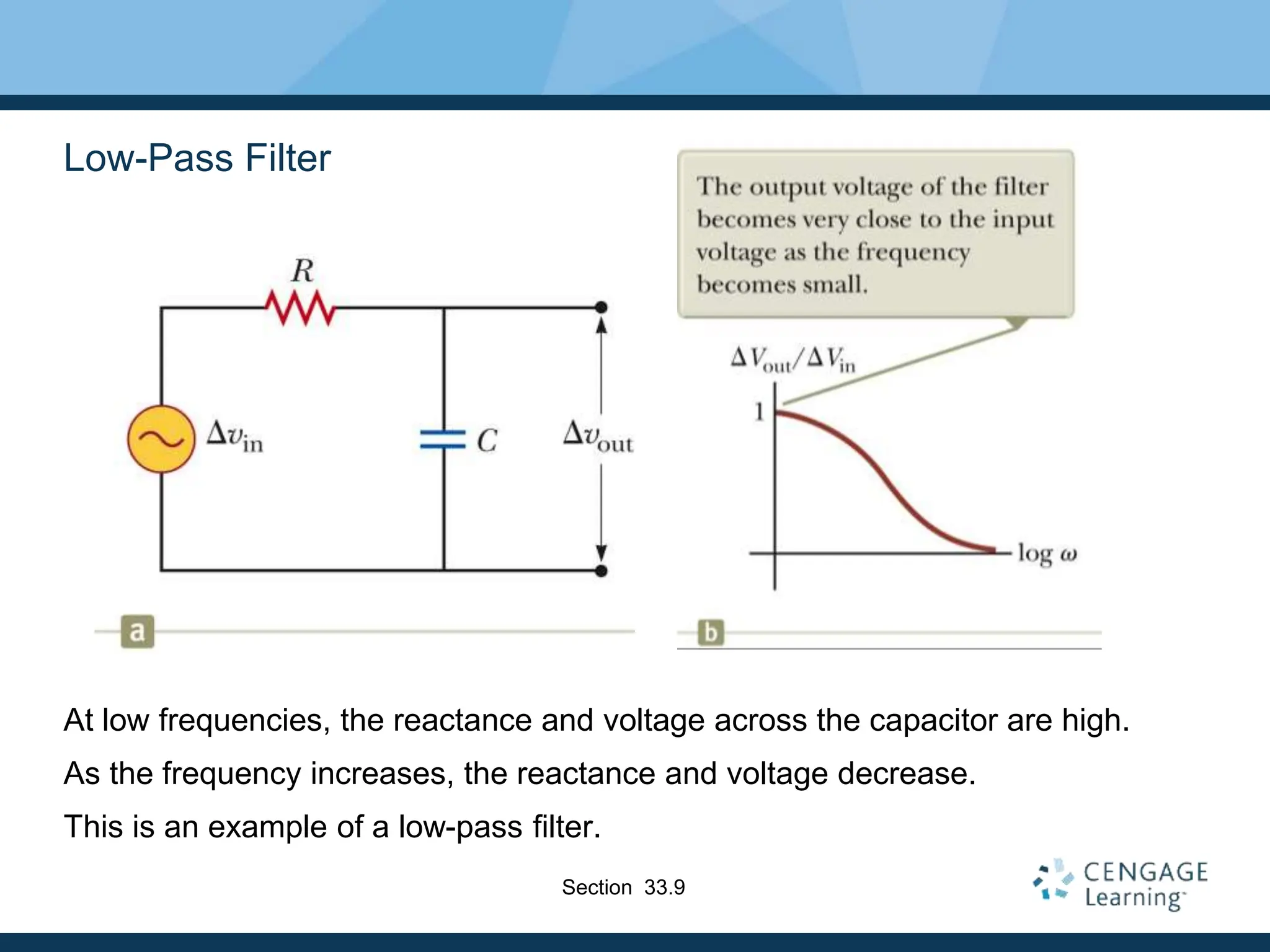
- Reactance (inductive or capacitive) describes how elements impede current at different frequencies.
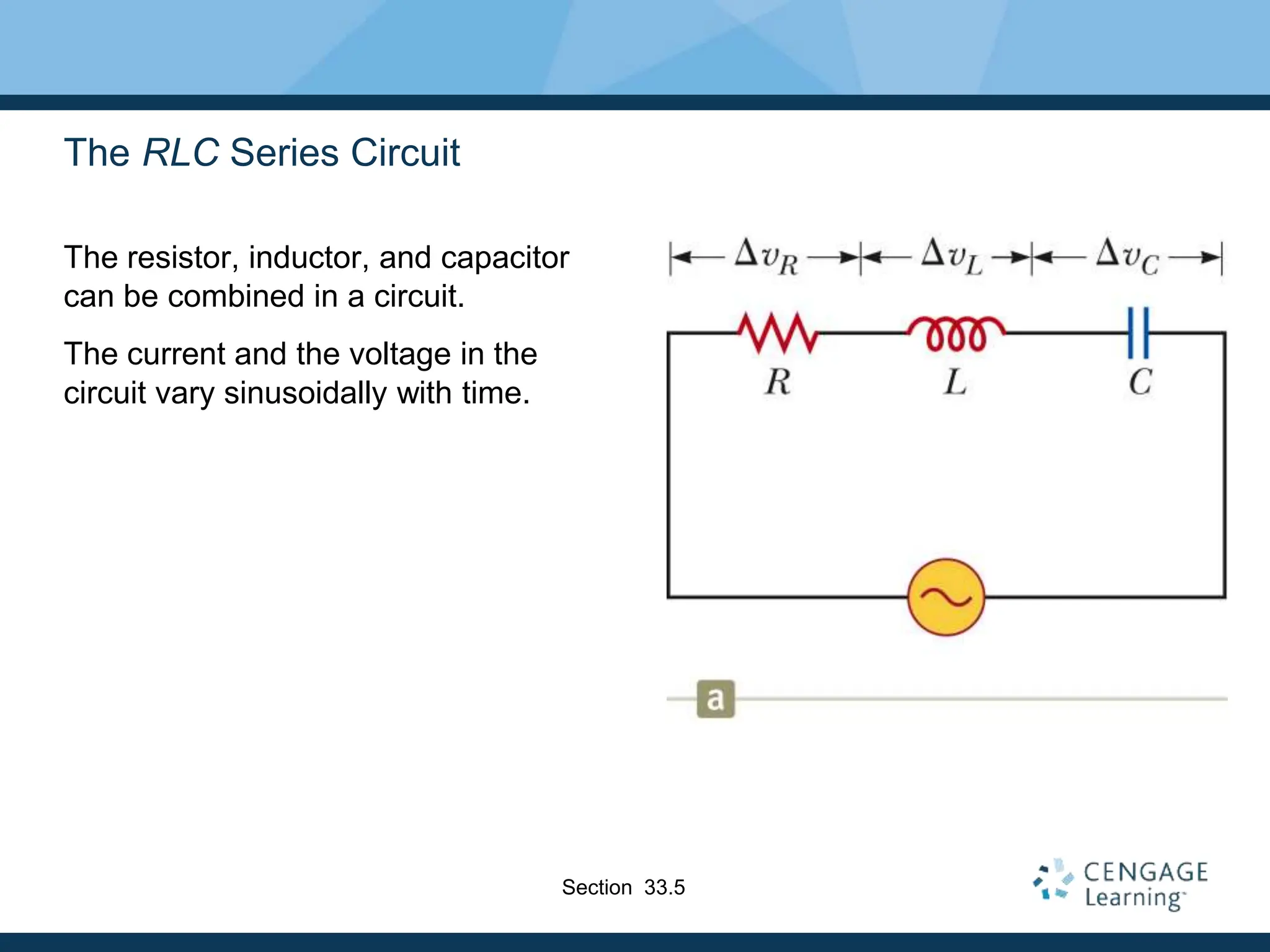
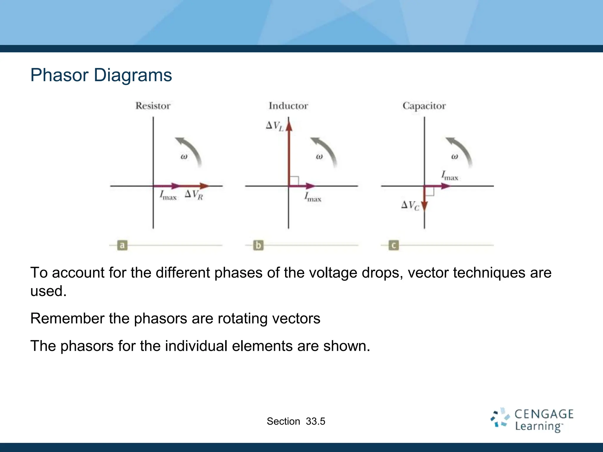
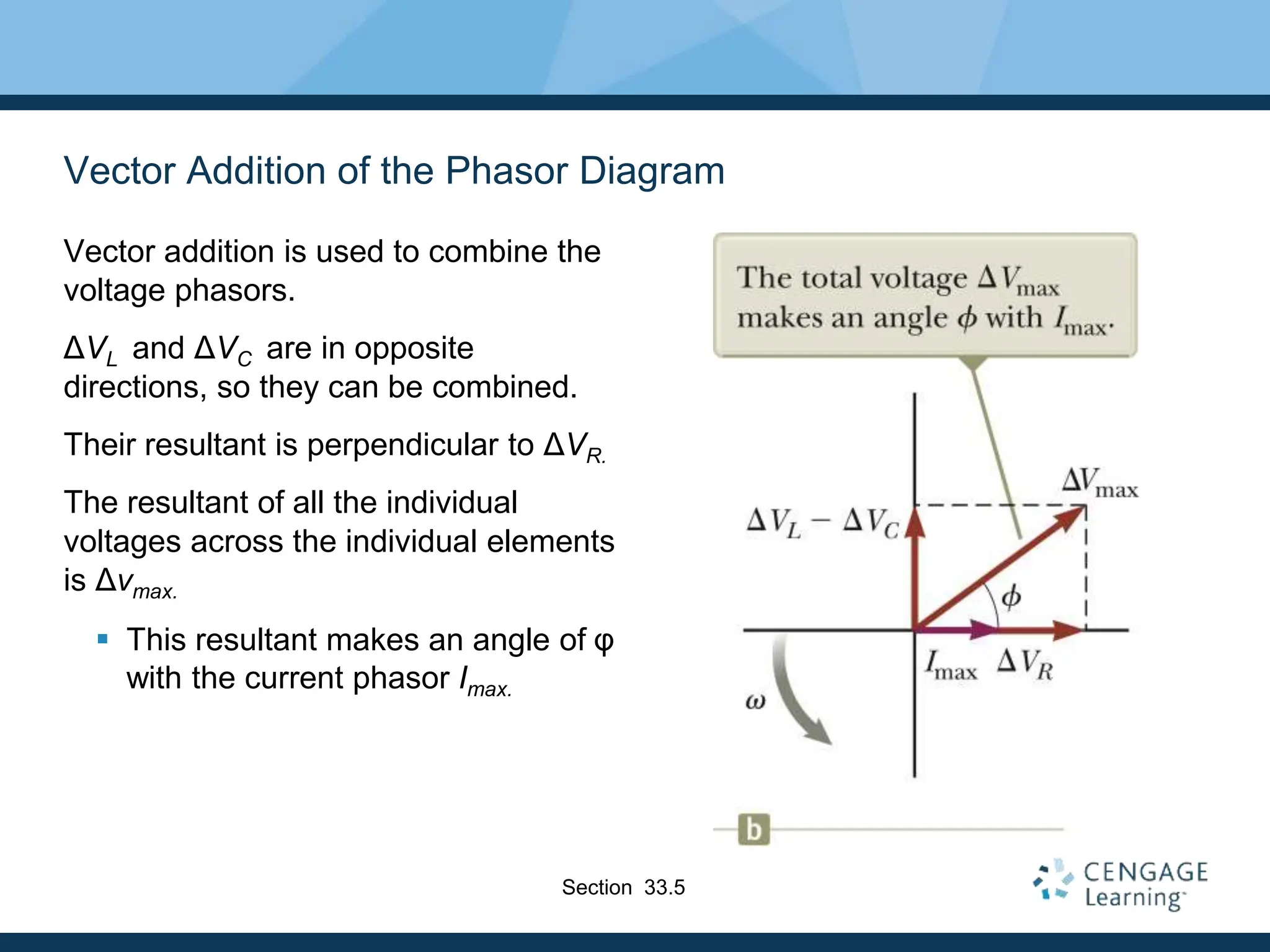
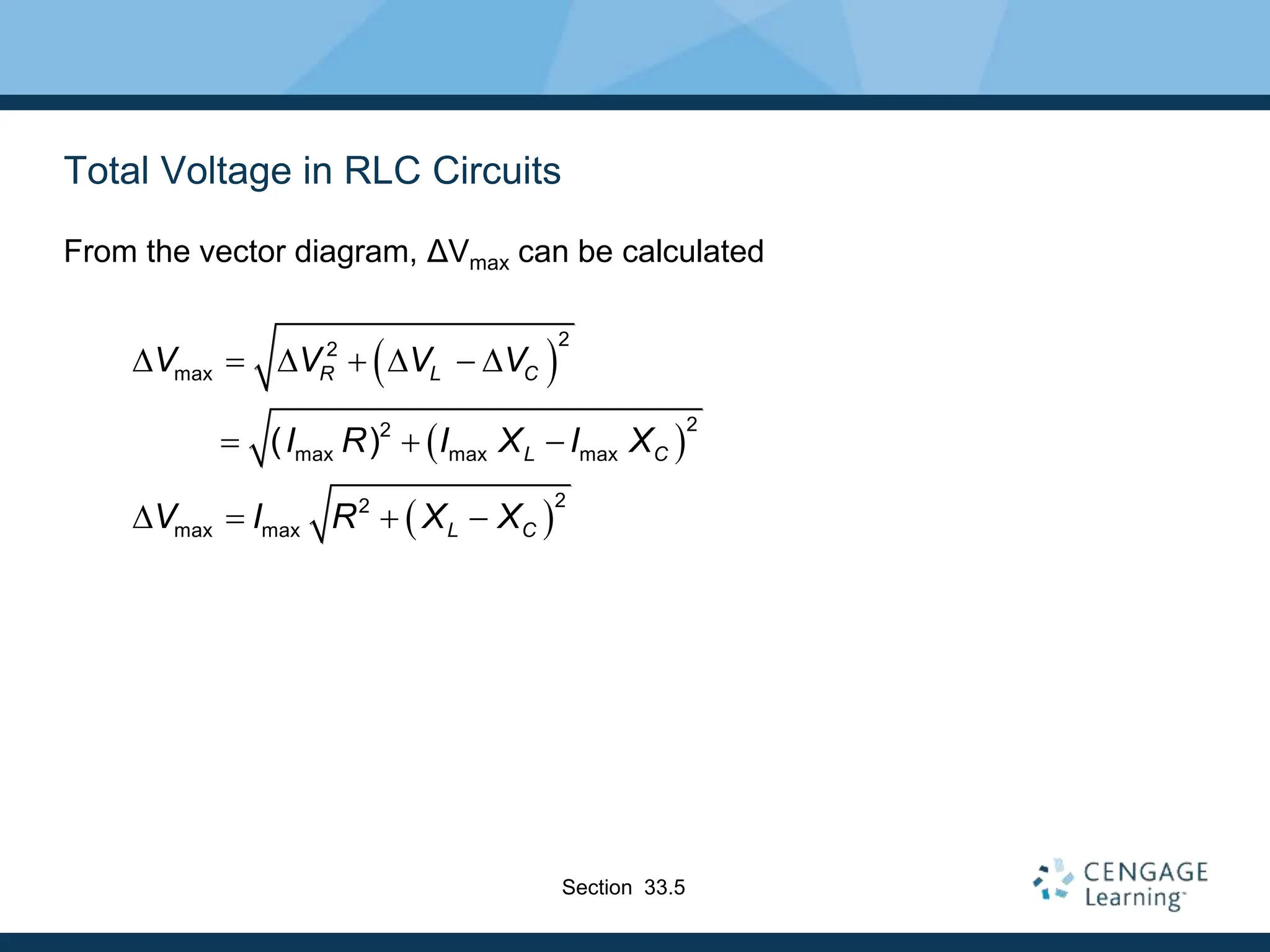
- RLC circuits combine these elements, requiring phasor analysis to understand voltage and current relationships. Impedance and