


![REFERENCES
[1] Theory and performance of Electrical Machines- J.B.Gupta / edition/ Published by
S Kataria & Sons.
[2] J. Barrett, T. Harned, J. Monnich, Linear Motor Basics, Parker Hannifin Corporation,
http://www.parkermotion.com/whitepages/linearmotorarticle.pdf
[3] Trilogy Linear Motor & Linear Motor Positioners, Parker Hannifin Corporation, 2008,
http://www.parkermotion.com/pdfs/Trilogy_Catalog.pdf
[4] “Descriptor-Type Kalman Filter and TLS EXIN Speed Estimate for Sensorless
Control of a Linear Induction Motor”Published by Francesco Alonge, Maurizio
Cirrincione, Filippo D’Ippolito, Marcello Pucci, Antonino Sferlazza, and
Gianpaolo Vitale in IEEE Journals on 6th Nov./Dec. 2014.
[5] “The linear induction motor (LIM) & single linear induction motor (SLIM)”
Published by Nahid Ahmadinia in American Journals on 20th July 2014.
[6] “Neural Sensorless Control of Linear Induction Motors by a Full-Order Luenberger
Observer Considering the End Effects”Published by Angelo Accetta, Maurizio
Cirrincione, Marcello Pucci, and Gianpaolo Vitale in IEEE Journals on 3h
May/June 2014.
25](https://image.slidesharecdn.com/lim-160521094626/75/Linear-Induction-Motor-25-2048.jpg)


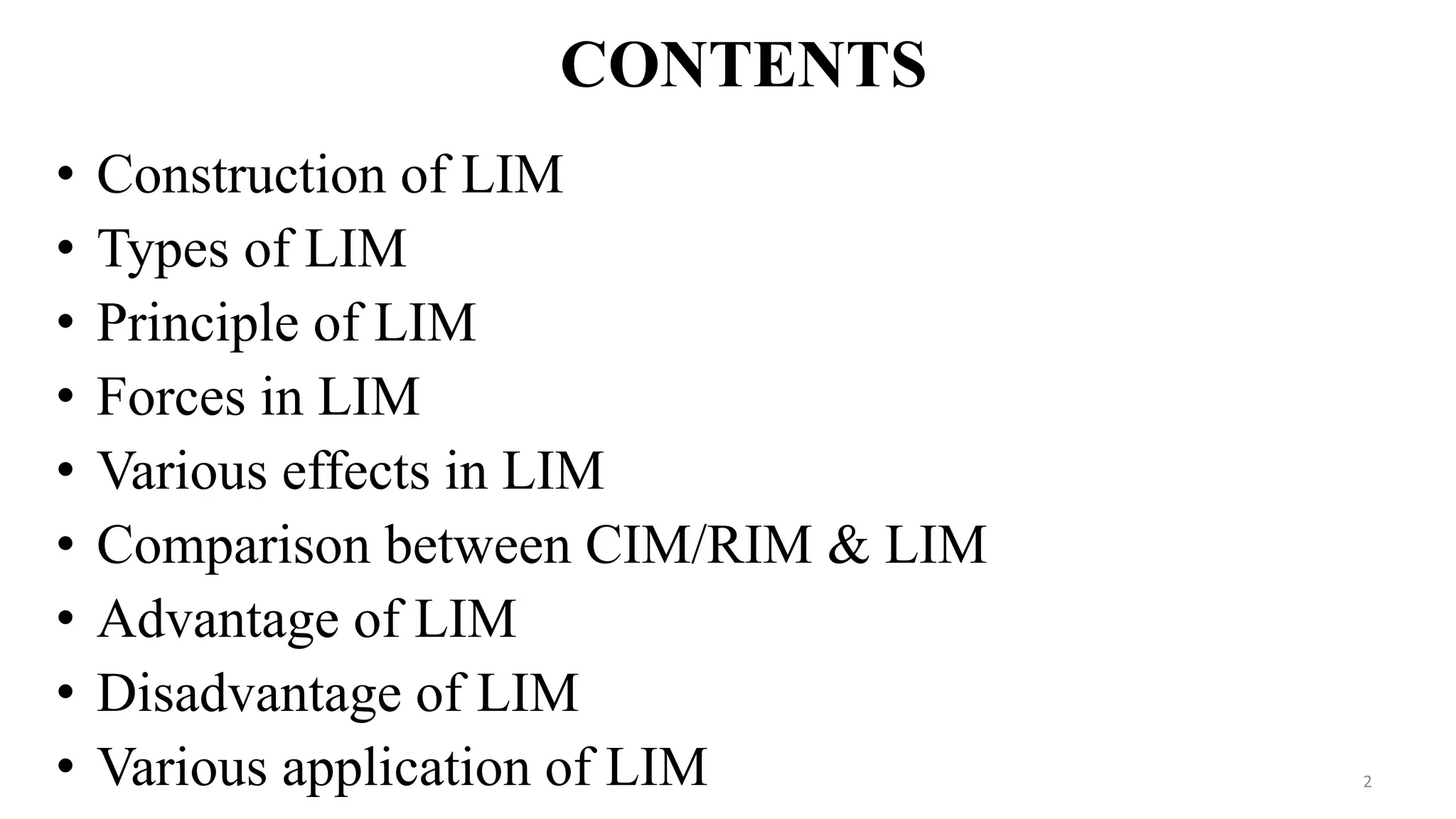
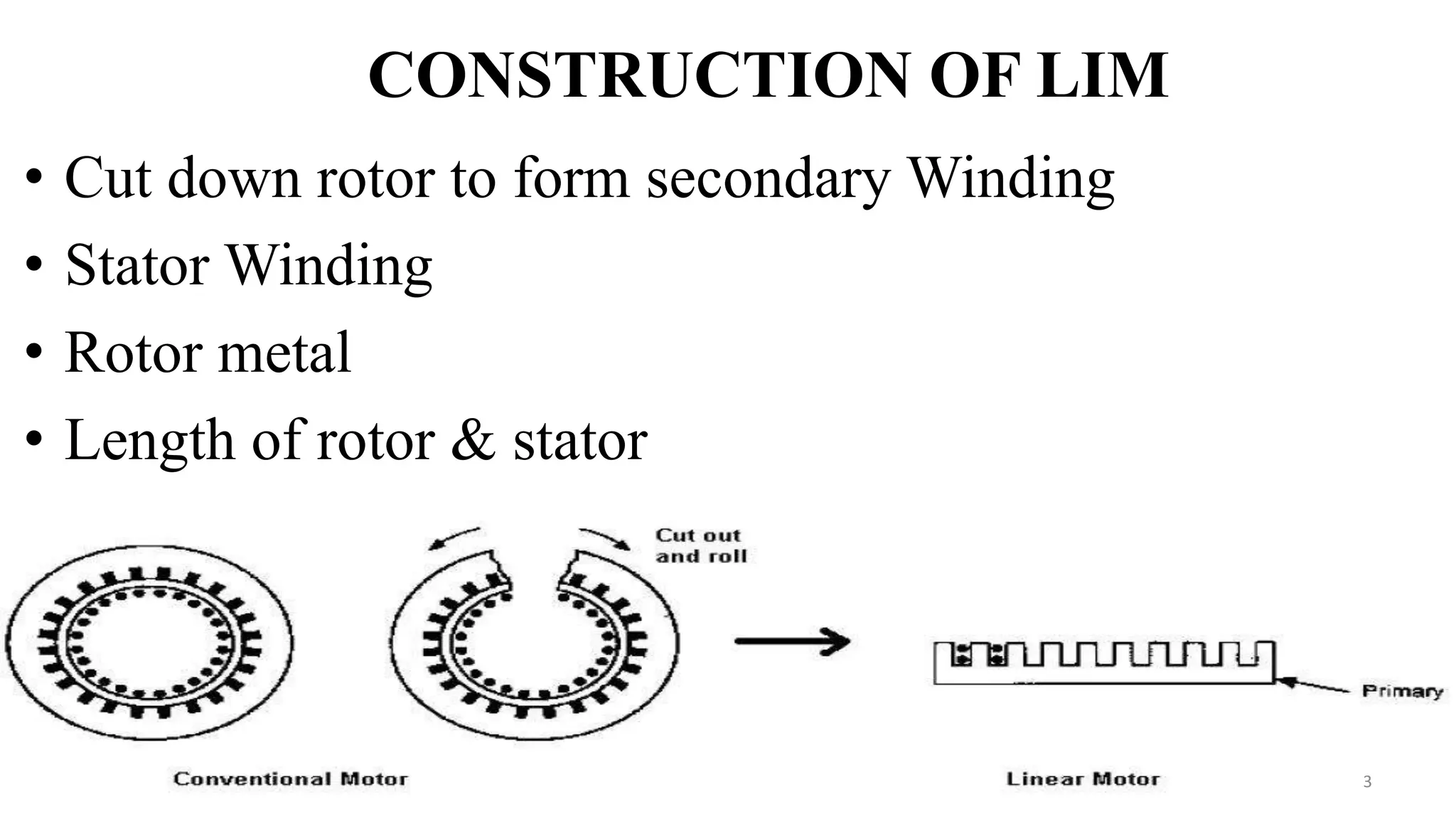
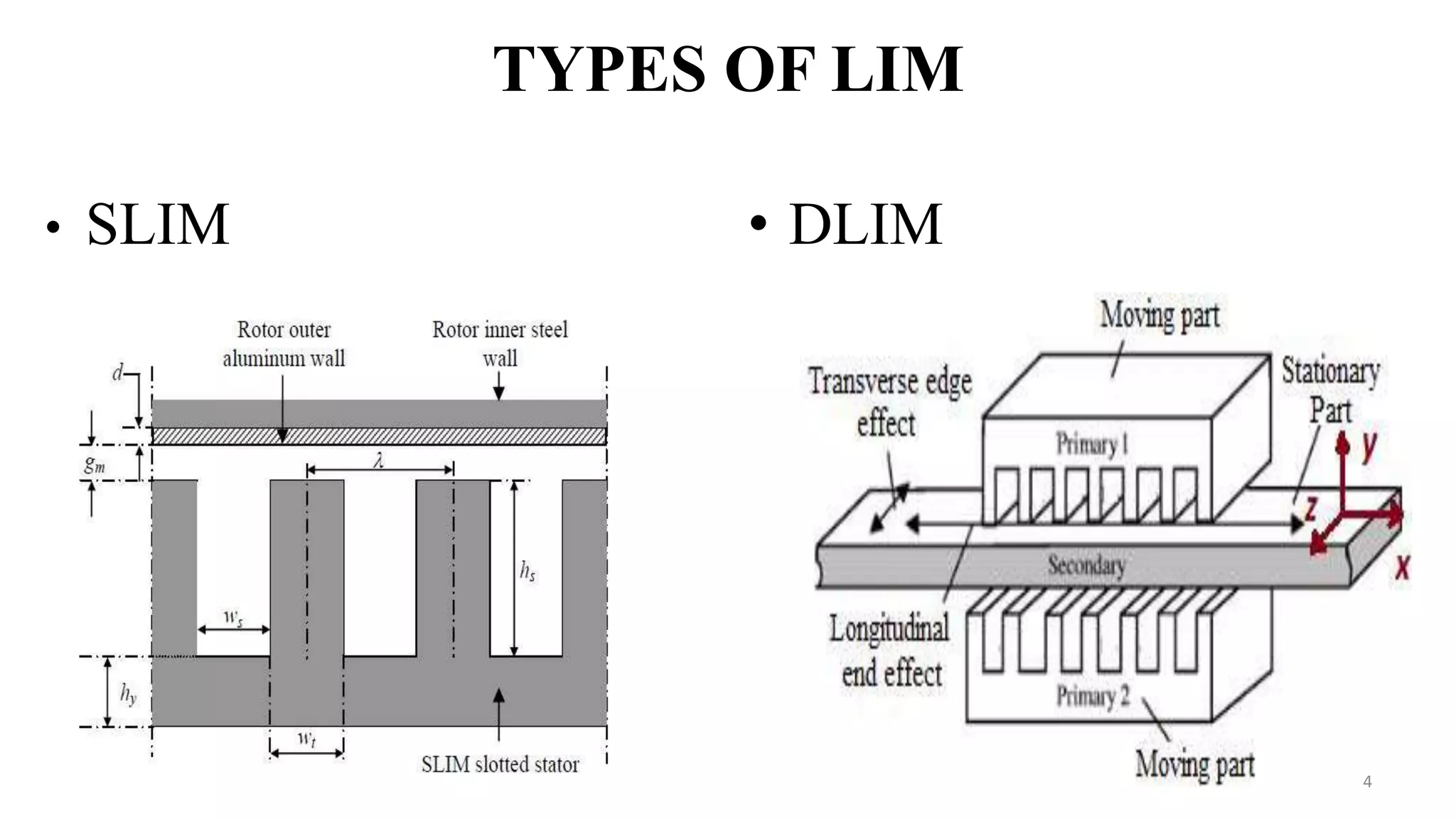
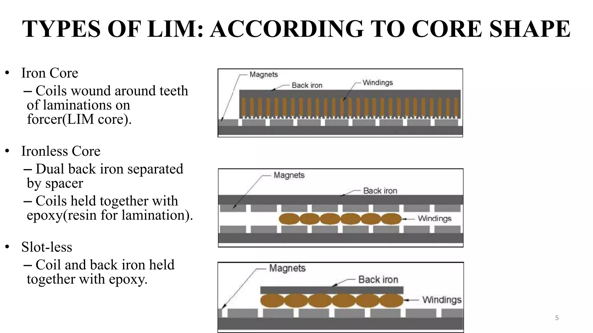
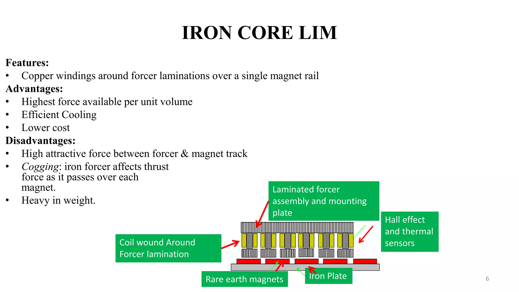
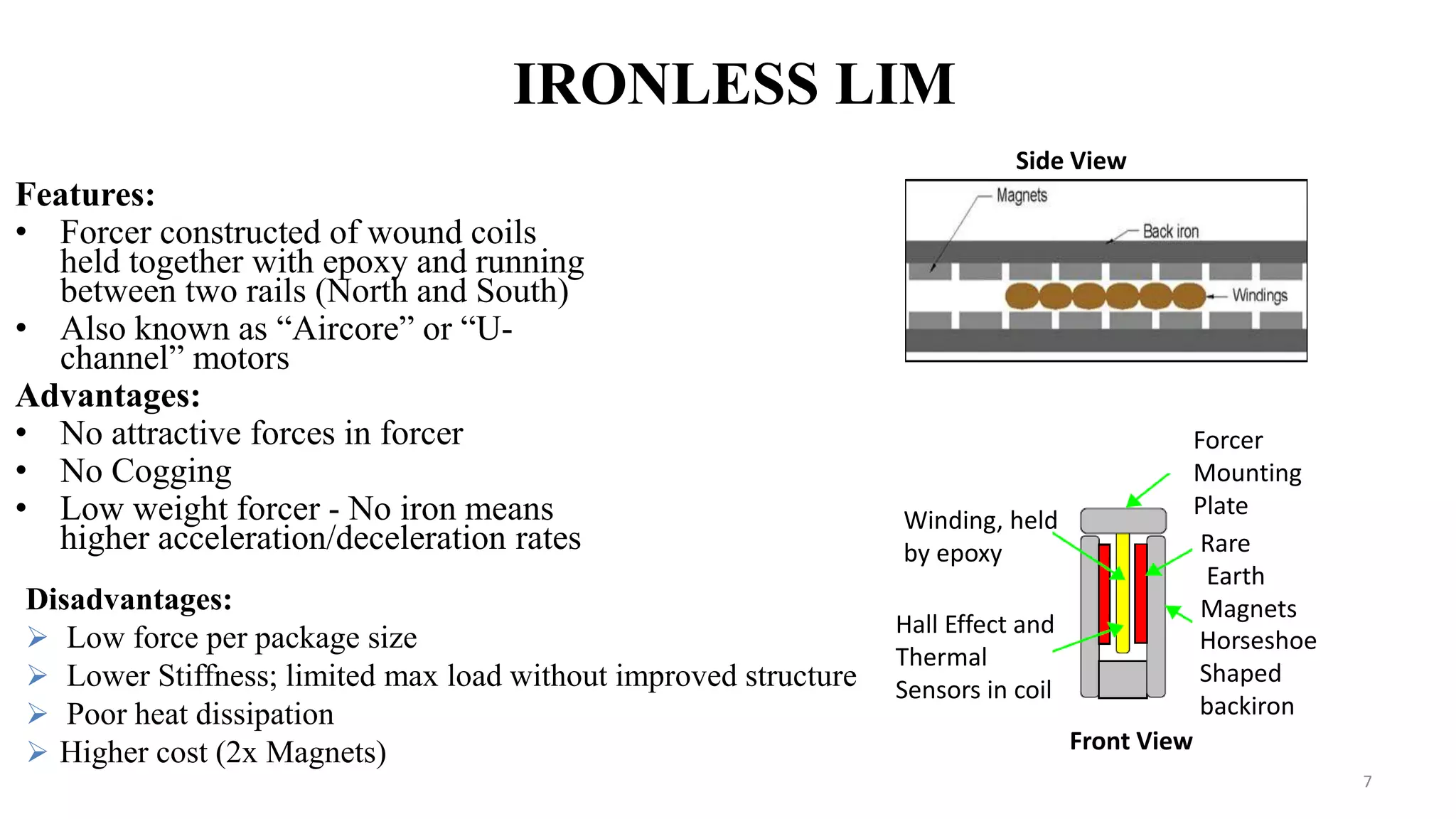
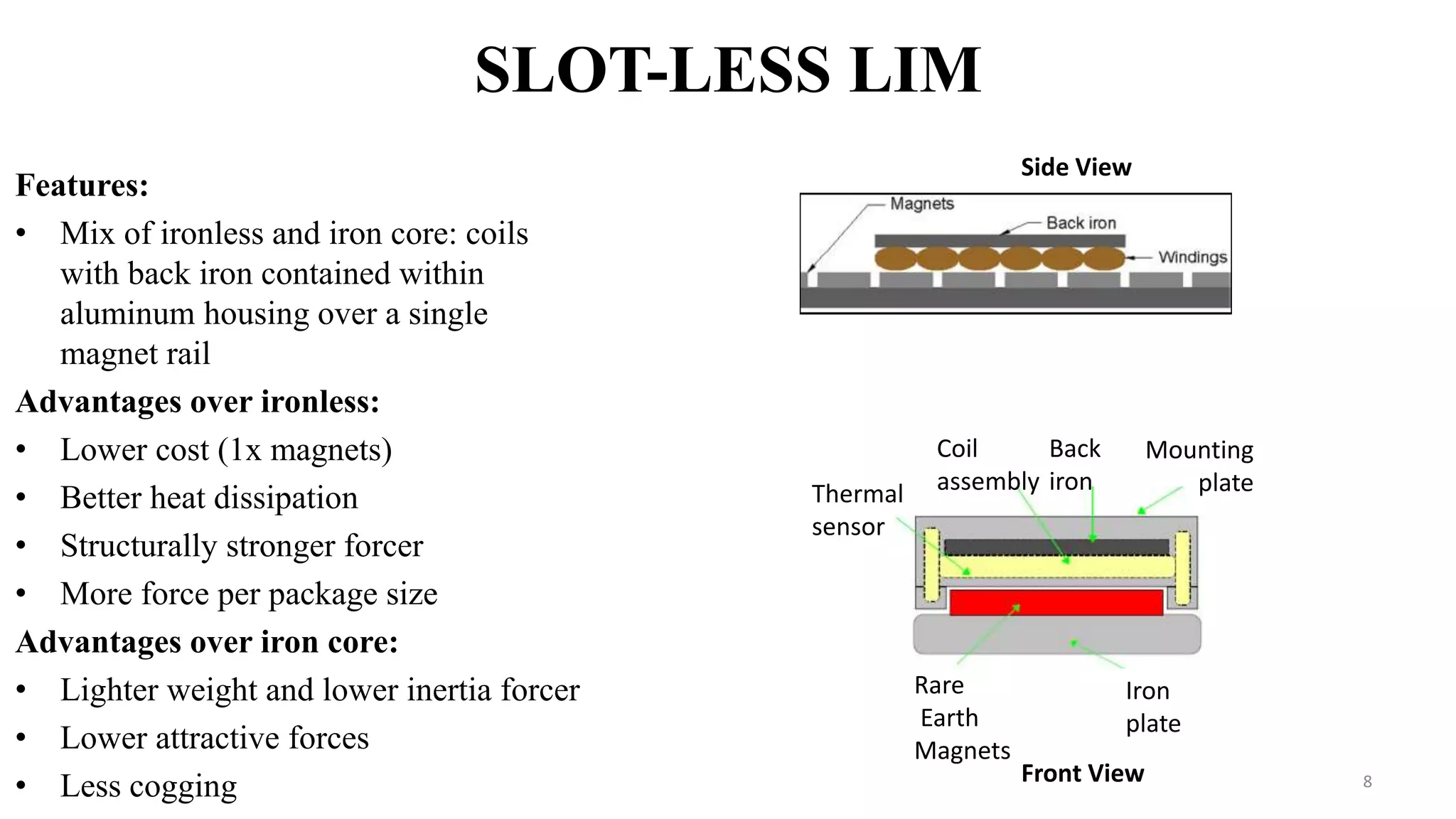
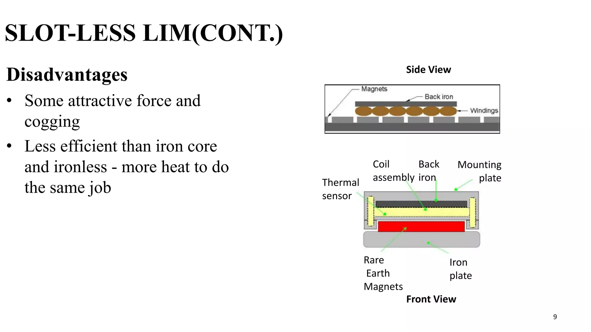
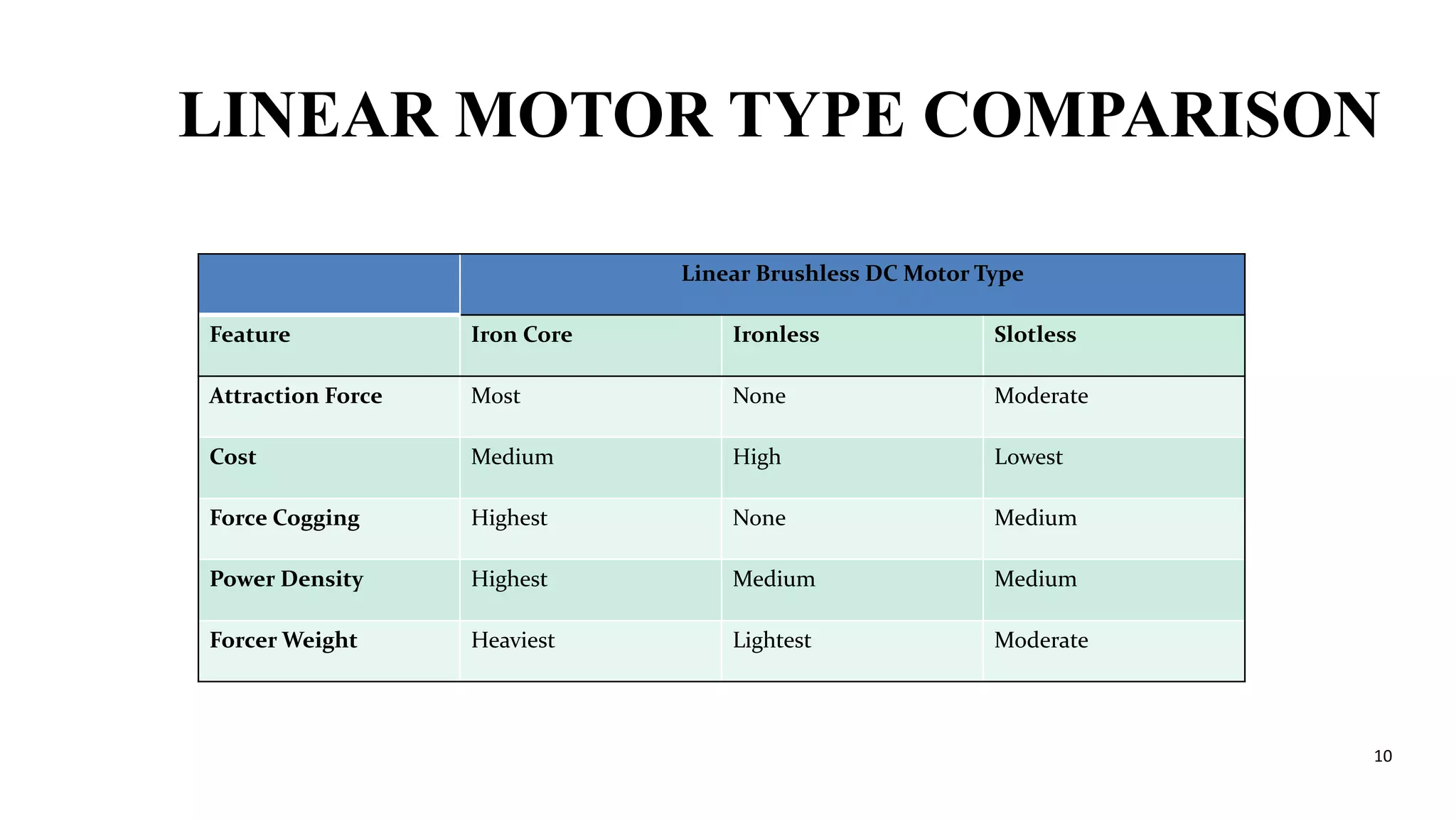
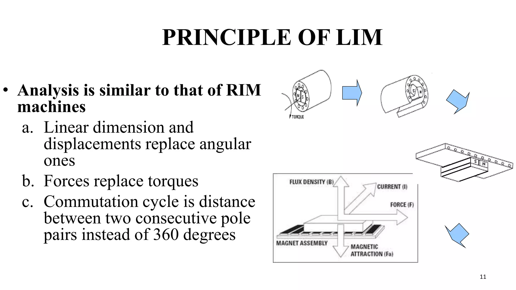
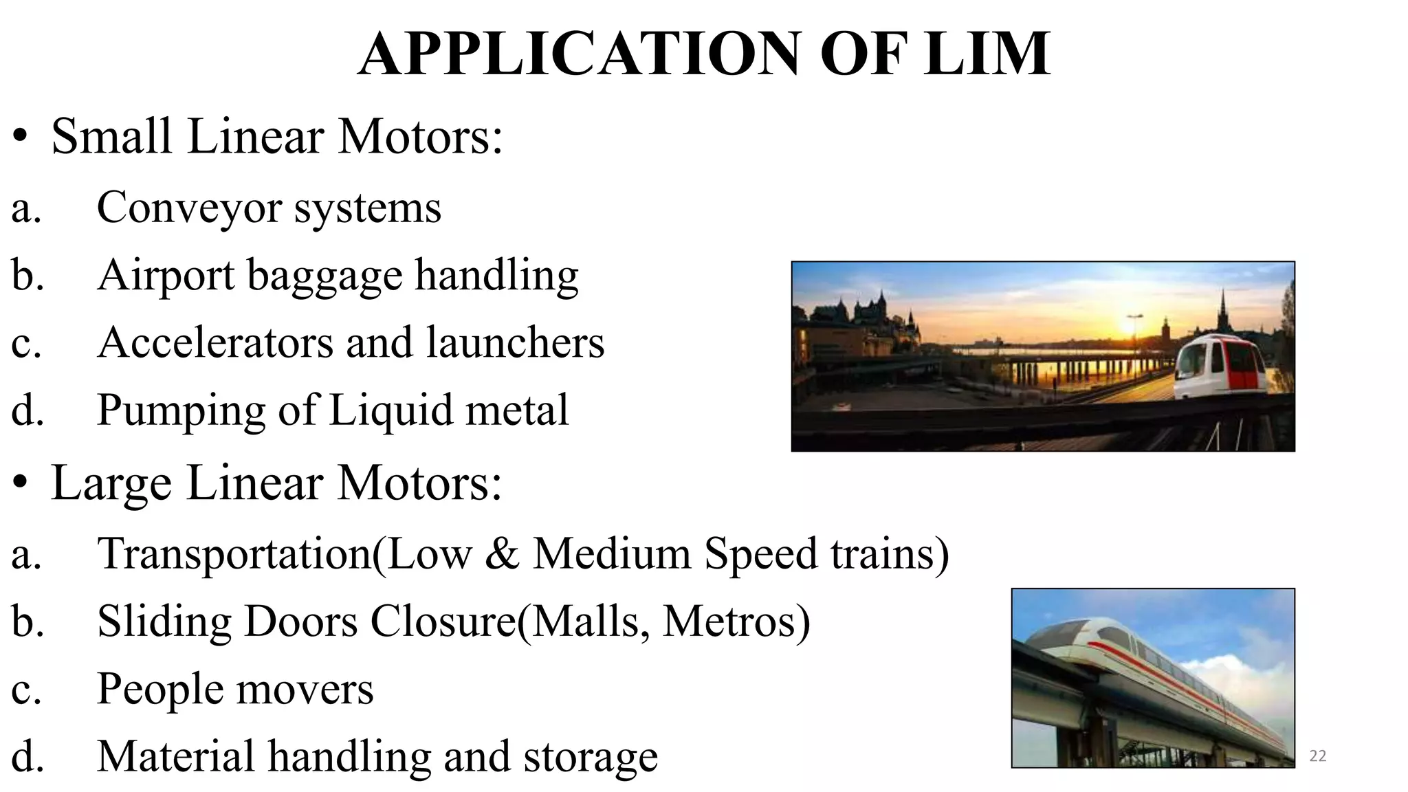
This seminar presentation summarizes the key aspects of linear induction motors (LIMs). It discusses the construction of LIMs, including their stator and rotor components. It describes the different types of LIMs according to their core shape, including iron core, ironless core, and slot-less designs. The presentation also covers the principles of operation of LIMs, the different forces involved, and various effects such as end effects and gap effects. It compares LIMs to conventional induction motors and rotary induction motors, outlines the advantages and disadvantages of LIMs, and discusses applications such as transportation and material handling where LIMs are commonly used.