Downloaded 657 times

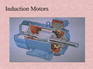
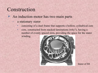
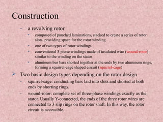
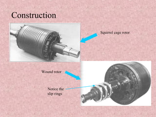
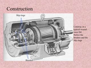
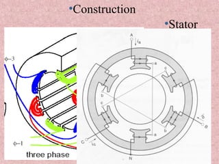
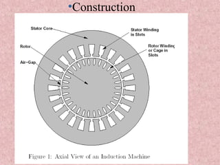
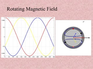
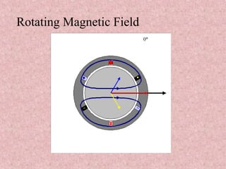
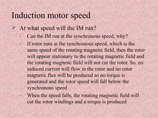
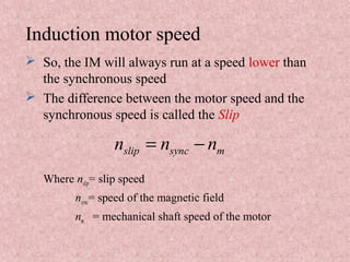


The document discusses three-phase induction motors. It begins by explaining that induction motors are the most common electric motors used in industry due to their simple and rugged design. It then covers the basic principles of operation, describing how a rotating magnetic field induces current in the rotor. It discusses the two main types - squirrel cage and wound rotor - and describes their construction features. The document also covers motor speed, how it is lower than synchronous speed due to slip, and the similarities and differences between induction motors and transformers. It concludes by listing the main power losses that occur in induction machines.


