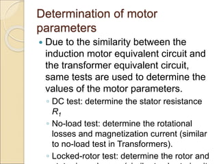
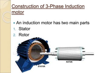
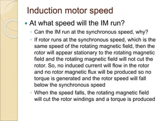
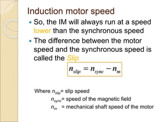
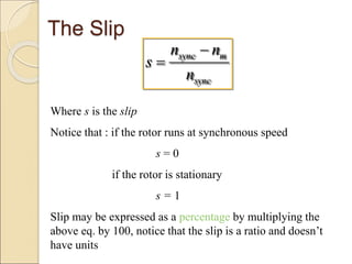
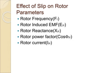
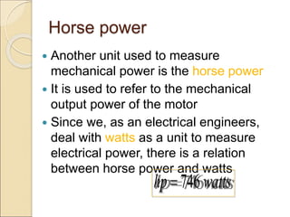
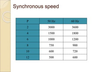
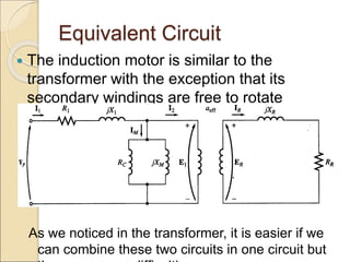
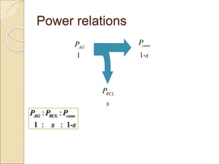
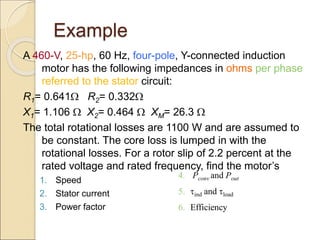
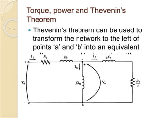
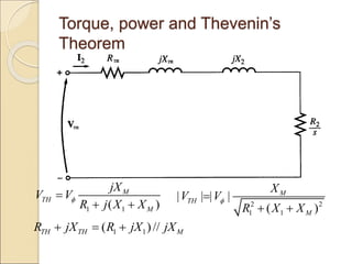
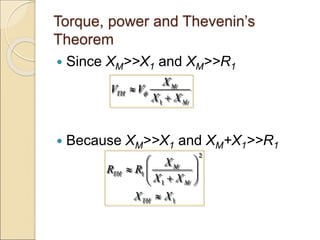
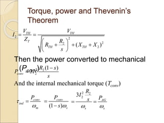
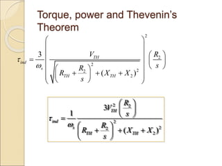
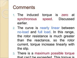
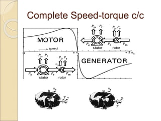
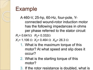
This document provides an overview of three-phase induction motors, including their construction, operation, and characteristics. It discusses the main components of induction motors, including the stator, squirrel cage rotor, and wound rotor. It explains how a rotating magnetic field is produced in the stator to induce voltage and current in the rotor. It also covers key concepts such as synchronous speed, slip speed, rotor frequency, torque production, and equivalent circuits. Power losses and relationships between input, output, and loss powers are also summarized.

![Solution
The torque at this speed is
2
max 2 2
2
2
2 2
3
1
2 ( )
3 (255.2)
2
2 (1800 )[0.590 (0.590) (1.106 0.464) ]
60
229 N.m
TH
s TH TH TH
V
R R X X
](https://image.slidesharecdn.com/inductionmachine-240401021412-78c44ec5/85/Induction-Machine-electrical-and-electronics-72-320.jpg)
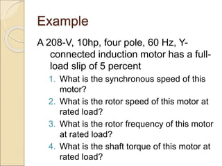
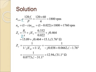
![Solution
2. The starting torque can be found from
the torque eqn. by substituting s = 1
2 2
2
1
2
2
2
1
2
2
2 2
2 2
2
2 2
3
1
( )
3
[ ( ) ]
3 (255.2) (0.332)
2
1800 [(0.590 0.332) (1.106 0.464) ]
60
104 N.m
TH
start ind s
s
TH TH
s
TH
s TH TH
R
V
s
R
R X X
s
V R
R R X X
](https://image.slidesharecdn.com/inductionmachine-240401021412-78c44ec5/85/Induction-Machine-electrical-and-electronics-73-320.jpg)
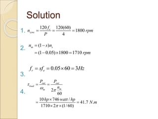
![Solution
The starting torque is now
2
2 2
3 (255.2) (0.664)
2
1800 [(0.590 0.664) (1.106 0.464) ]
60
170 N.m
start
](https://image.slidesharecdn.com/inductionmachine-240401021412-78c44ec5/85/Induction-Machine-electrical-and-electronics-75-320.jpg)