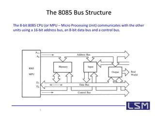
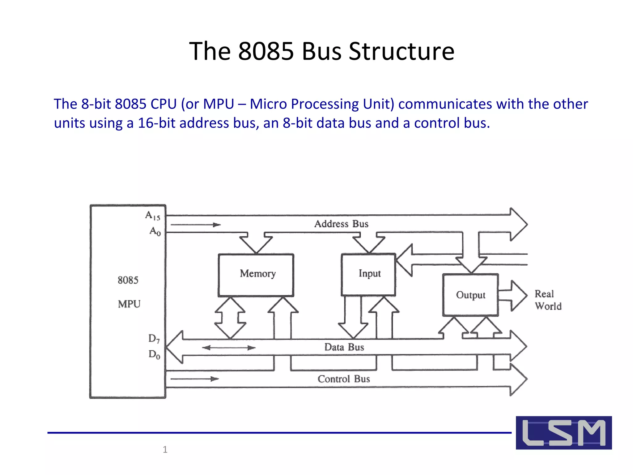
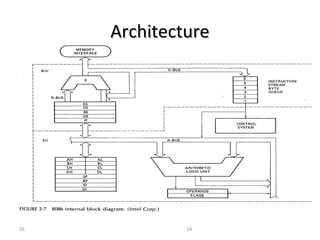
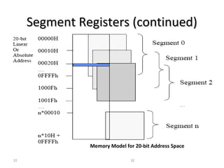
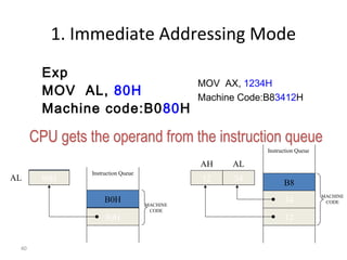
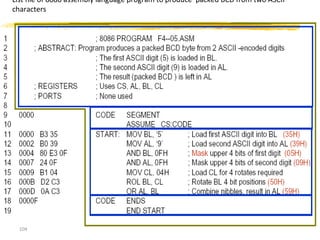
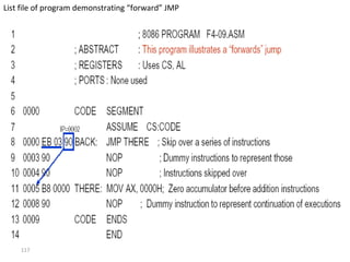
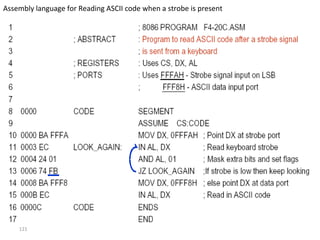
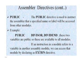
The 8085 CPU communicates with other units using a 16-bit address bus, 8-bit data bus, and control bus. It has 16 address lines that can access up to 64K memory locations. The data bus is bidirectional and has 8 lines. The 8085 also has internal registers like the accumulator, flag bits, program counter, and stack pointer to perform operations and sequence instruction execution. It uses different addressing modes like immediate, register, and memory to specify the source and destination operands.
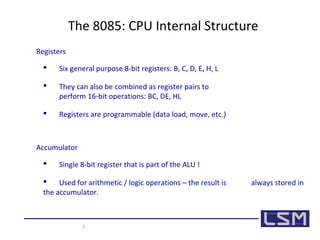

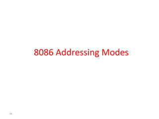
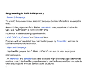
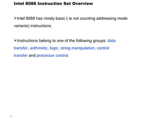
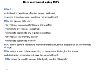
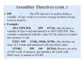
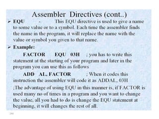
![3. Memory Addressing Mode
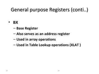
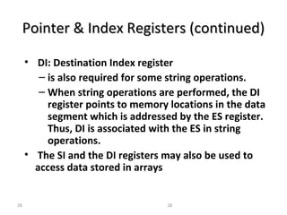
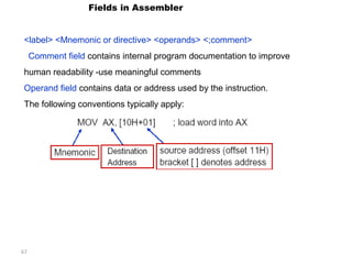
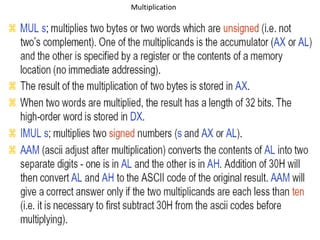
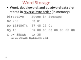
• Specify an offset address (effective address) using expressions of the form (different parts of
expression are optional):
– [ Base Register + Index Register+ Displacement]
• 1) Base Register---BX, BP
• 2) Index Register---SI, DI
• 3) Displacement ---constant value
• Example: 1) add ax,[20h] 2) add ax,[bx]
42
3) add ax,[bx+20h] 4) add ax, [bx+si]
5) add ax, [bx+si+20h]](https://image.slidesharecdn.com/unit-1-mpi-140822043125-phpapp01/85/MPMC-Unit-1-42-320.jpg)
![43
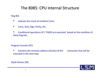
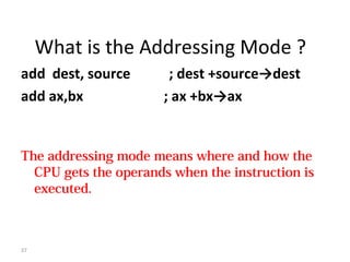
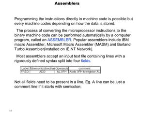
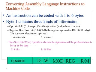
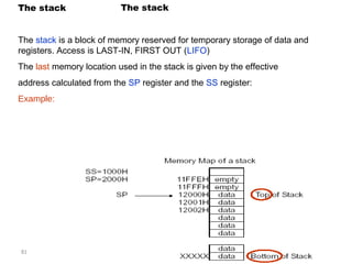
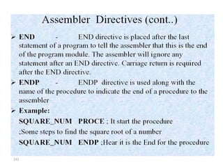
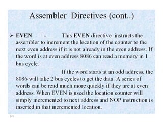
3. Memory Addressing Mode
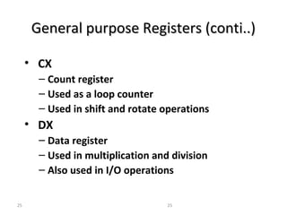
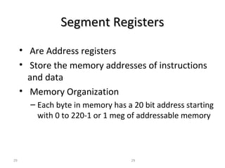
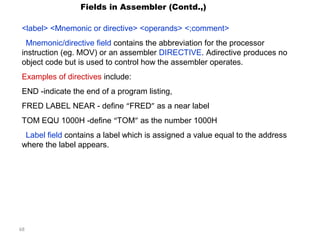
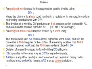
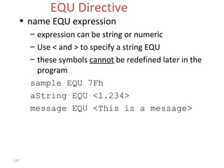
⑴ Direct Addressing Mode
Exp: MOV AL, [1064H]
Machine code:A06410H
• The offset address of the operand is provided in the
instruction directly;
• The physical address can be calculated using the content
of DS and the offset :
PA = (DS)*10H+Offset](https://image.slidesharecdn.com/unit-1-mpi-140822043125-phpapp01/85/MPMC-Unit-1-43-320.jpg)
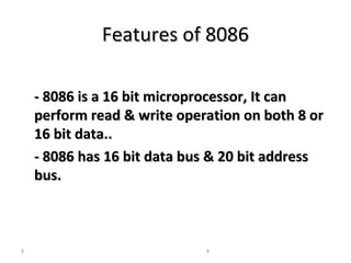
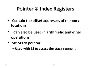
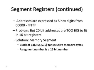
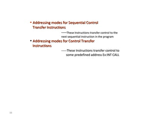
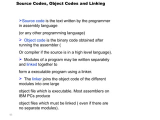
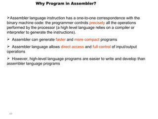
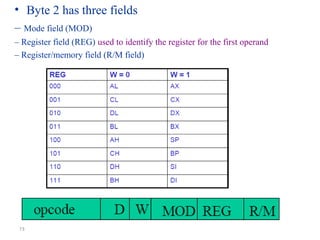
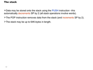
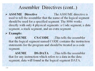
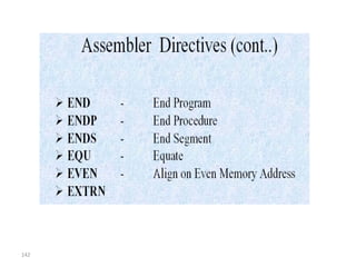
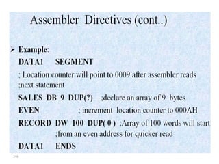
![⑴ Direct Addressing Mode
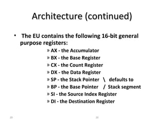
Example: MOV AL, [1064h] ;Assume (DS)=2000H
Machine code: A06410H
44
(DS)*10H=20000H
+ 1064H
21064H
20000H
21064H
AL
A0
64
10
…
45
Code
Segment
Data
Segment
45](https://image.slidesharecdn.com/unit-1-mpi-140822043125-phpapp01/85/MPMC-Unit-1-44-320.jpg)
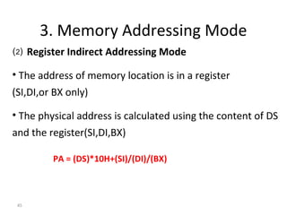
![46
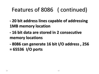
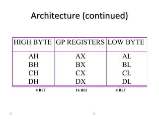
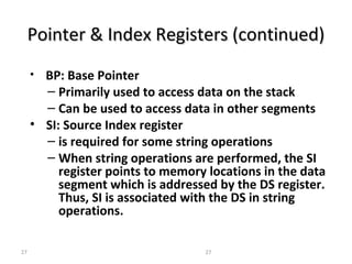
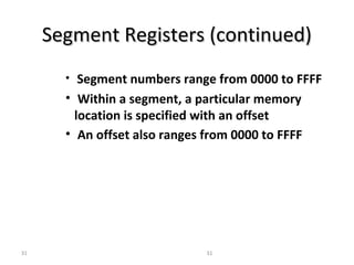
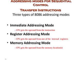
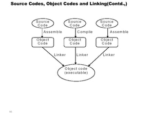
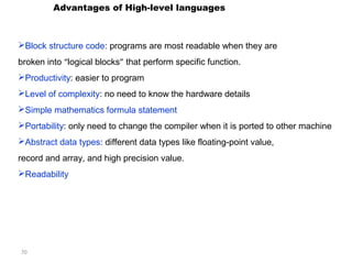
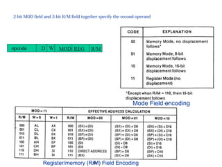
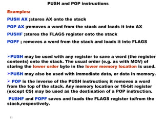
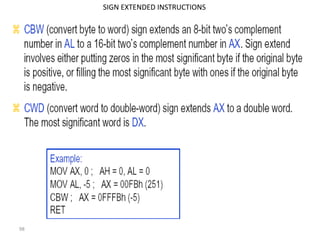
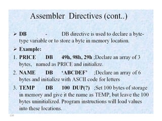
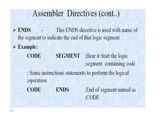
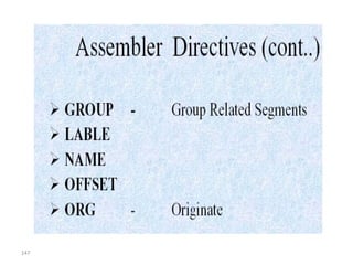
⑵ Register Indirect Addressing Mode
ASSUME: (DS)=3000H, (SI)=2000H, (BX)=1000H
MOV AX, [SI] MOV [BX], AL
M
… …
50
40
AX
30000H
(DS)*10H=30000H
+ (SI)= 2000H
32000H
32000H
40 50
… …
(DS)*10h= 30000H
+ (BX)= 1000H
64H
M
31000H
AL 30000H
31000H
64H](https://image.slidesharecdn.com/unit-1-mpi-140822043125-phpapp01/85/MPMC-Unit-1-46-320.jpg)
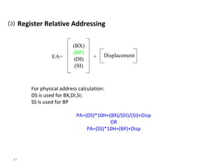
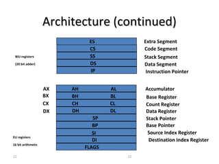
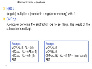
![⑶ Register Relative Addressing
MOV CL, [BX+1064H] ;assume: (DS)=2000h, (bx)=1000h
48
;Machine Code: 8A8F6410
(DS)*10h= 20000H
(BX)= 1000H
+ 1064H
22064H
20000H
22064H
8F
64
10
…
45
Code
Segment
Data
Segment
8A
…
CL
45 21000H
PPAA==((ddss))**1100hh++((bbxx))++11006644hh](https://image.slidesharecdn.com/unit-1-mpi-140822043125-phpapp01/85/MPMC-Unit-1-48-320.jpg)
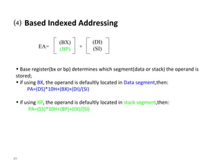
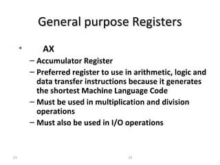
![⑷ Based Indexed Addressing
Example: MOV AH, [BP][SI];Assume(ss)=4000h,(bp)=2000h,(si)=1200h
PPAA==((ssss))**1100hh++((bbpp))++((ssii))
50
M
… …
AH 40000H
56H
(SS)*10H= 40000H
(BP)= 2000H
+
43200H
43200H
(SI)= 1200H
56H](https://image.slidesharecdn.com/unit-1-mpi-140822043125-phpapp01/85/MPMC-Unit-1-50-320.jpg)
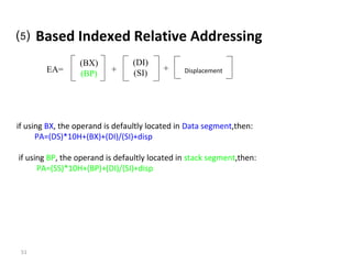
![⑸ Based Indexed Relative Addressing
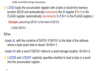
MOV [BX+DI+1234H], AH
;assume (ds)=4000h,(bx)=0200h,(di)=0010h
;machine code:88A13412h
52
A1
34
12
…
Code
segment
Data
segment
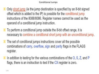
88
…
(DI)= 0010H
AH 45
40000H
(DS)*10H=40000H
(BX)= 0200H
+
1234H
45
41444H
41444H](https://image.slidesharecdn.com/unit-1-mpi-140822043125-phpapp01/85/MPMC-Unit-1-52-320.jpg)
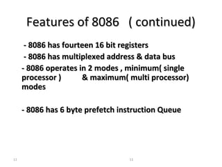
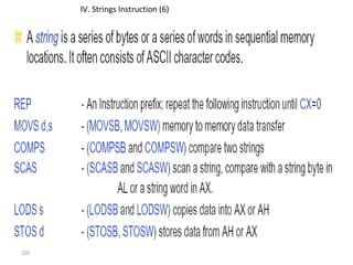
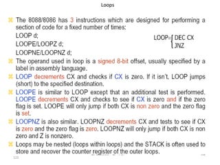
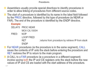
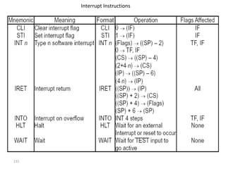
![Summary on the 8086 memory addressing modes
1. Direct Addressing [disp] disp DS CS ES SS
2. Register [BX]/[SI] /[DI] Content of the R DS CS ES SS
Indirect Addressing
53
operand offset address Default Overridden
(effective address ) Segment Register Segment
Register
3. Register [SI/DI/BX/BP+disp] (SI)/(DI)/(BX)/(BP)+disp DS CS ES SS
Relative Addressing
4. Based Indexed [BX+SI/DI] (BX)+disp DS CS ES SS
Addressing [BP+SI/DI] (BP)+disp SS CS ES DS
5. Based Indexed [BX+SI/DI+disp] (BX)+(SI)/(DI)+disp DS CS ES SS
Relative Addressing [BP+SI/DI+disp] (BP)+(SI)/(DI)+disp SS CS ES DS](https://image.slidesharecdn.com/unit-1-mpi-140822043125-phpapp01/85/MPMC-Unit-1-53-320.jpg)
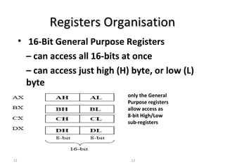
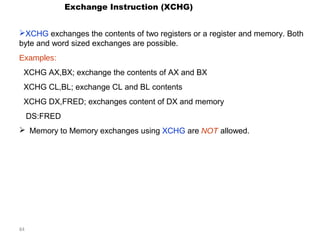
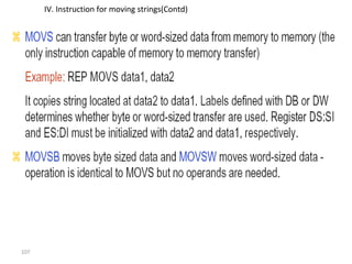
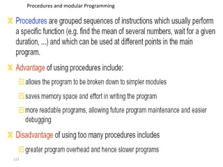
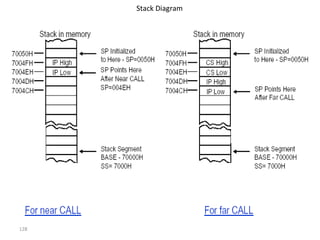
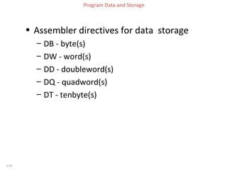
![Examples:
Assume: (BX)=6000H, (BP)=4000H, (SI)=2000H,
(DS)=3000H, (ES)=3500H, (SS)=5000H
IInnssttrruuccttiioonn aaddddrreessssiinngg llooggiiccaall pphhyyssiiccaall
1. MOV AX, [0520H]
mmooddee aaddddrreessss aaddddrreessss
Register Indirect Addressing 3000:6000 36000H
3. MOV AX, [SI+1000H] 3000:3000 33000H
4. MOV AX, [BP+6060H]
54
Direct Addressing 3000:0520 30520H
2. MOV AX, [BX]
Register Relative Addressing
Register Relative Addressing
5. MOV AX, ES: [BX+SI+0050H]
5000:A060 5A060H
Based Indexed Relative 3500:8050 3D050H
Addressing](https://image.slidesharecdn.com/unit-1-mpi-140822043125-phpapp01/85/MPMC-Unit-1-54-320.jpg)
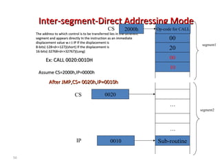
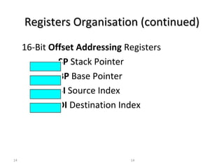
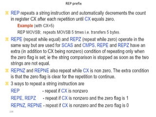
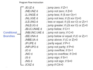
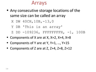
![57
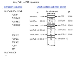
Inter-sseeggmmeenntt--IINN--DDiirreecctt AAddddrreessssiinngg MMooddee
TThhee aaddddrreessss ttoo wwhhiicchh ccoonnttrrooll iiss ttoo bbee ttrraannssffeerrrreedd
lliieess iinn tthhee ddiiffffeerreenntt sseeggmmeenntt aanndd iitt iiss ppaasssseedd ttoo
tthhee
iinnssttrruuccttiioonn iinnddiirreeccttllyy ii..ee ccoonntteennttss ooff aa mmeemmoorryy
bblloocckk
ccoonnttaaiinniinngg ffoouurr bbyytteess
IIPP((LLSSBB)),,IIPP((MMSSBB)),,CCSS((LLSSBB)),,CCSS((MMSSBB))
EExx:: CCAALLLL [[BBXX]]
IP(LSB)10
IP(MSB)00
CS(LSB)20
…
Sub-routine
segment1
…
CS 3000h
BBeeffoorree JJMMPP,,AAssssuummee BBXX==110000hh,, CCSS==33000000hh,,IIPP==220000hh
CS 0020
Op-code for CALL
AAfftteerr JJMMPP,,CCSS== 00002200hh,,IIPP==00001100hh
segment2
IP 0010
CS(MSB)00
IP 0010](https://image.slidesharecdn.com/unit-1-mpi-140822043125-phpapp01/85/MPMC-Unit-1-57-320.jpg)
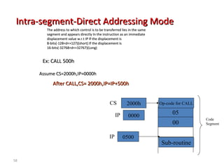
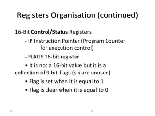
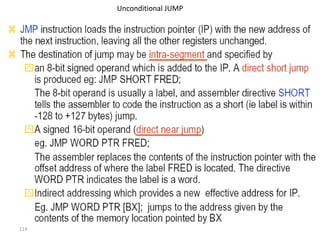
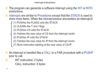
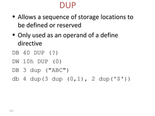
![seg Intra-segmmeenntt--IInn--DDiirreecctt AAddddrreessssiinngg MMooddee
59
IInn tthhiiss mmooddee tthhee ddiissppllaacceemmeenntt ttoo wwhhiicchh ccoonnttrrooll iiss ttoo bbee ttrraannssffeerrrreedd,,
IIss iinn tthhee ssaammee sseeggmmeenntt iinn wwhhiicchh tthhee ccoonnttrrooll ttrraannssffeerr iinnssttrruuccttiioonn lliieess
BBuutt iitt iiss ppaasssseedd ttoo tthhee iinnssttrruuccttiioonn iinnddiirreeccttllyy
CS 2000h Op-code for CALL
IP
EExx:: CCAALLLL [[BBXX]]
Code
Segment
AAssssuummee CCSS==22000000hh,,IIPP==00000000hh ,, BBXX==880000hh
AAfftteerr CCAALLLL,,CCSS== 22000000hh,,IIPP==IIPP++880000hh
05
00
0800
Sub-routine
IP 0000](https://image.slidesharecdn.com/unit-1-mpi-140822043125-phpapp01/85/MPMC-Unit-1-59-320.jpg)
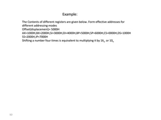
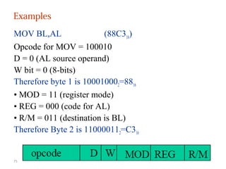
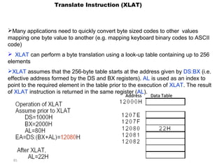
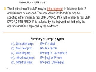
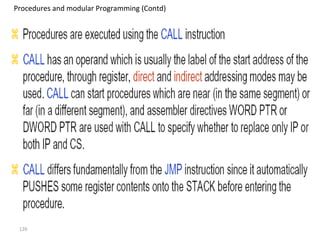
![Examples:
MOV BL, AL = 10001000 11000011 = 88 C3h
ADD AX, [SI] = 00000011 00000100 = 03 04 h
ADD [BX] [DI] + 1234h, AX = 00000001 10000001 __ __ h =
76
01 81 34 12 h](https://image.slidesharecdn.com/unit-1-mpi-140822043125-phpapp01/85/MPMC-Unit-1-76-320.jpg)
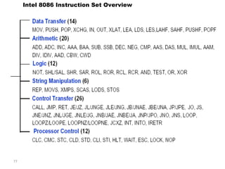
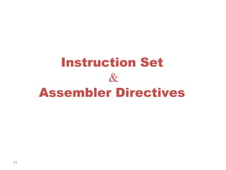
![86
LEA &LDS
LEA loads the offset of a memory address into a 16-bit register. The offset address
may be specified by any of the addressing modes.
Examples (with BP=1000H):
LEA AX,[BP+40H];=>SS:[1000H+40H] =SS:[1040H];load 1040H into AX
LEA BX,FRED; load the offset of FRED (in data segment) to BX
LEA CX,ES:FRED; loads the offset of FRED (in extra segment) to CX
LDS -Load data and DS
LDS reads two words from the consecutive memory locations and loads them into the
specified register and the DS segment registers.
Examples (DS=1000H initially)
LDS BX,[2222H]; copies content of 12222H to BL, 12223H to BH, and 12224 and
12225 to DS register
LDS is useful for initializing the SI and DS registers before a string operation. E.g.
LDS SI, sting_pointer
The source for LDS can be displacement, index or pointer register (except SP).](https://image.slidesharecdn.com/unit-1-mpi-140822043125-phpapp01/85/MPMC-Unit-1-86-320.jpg)
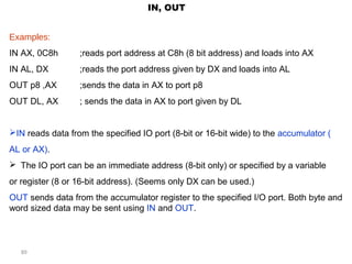
![87
LES -Load data and ES
LES reads two words from memory and is very similar to LDS except that the second
word is stored in ES instead of DS.
LES is useful for initializing that DI and ES registers for strings operation.
Example (with DS=1000H):
LES DI, [2222H]; loads DI with contents stored at 12222H and 12223H and loads ES
with contents at 12224 and 12225H](https://image.slidesharecdn.com/unit-1-mpi-140822043125-phpapp01/85/MPMC-Unit-1-87-320.jpg)
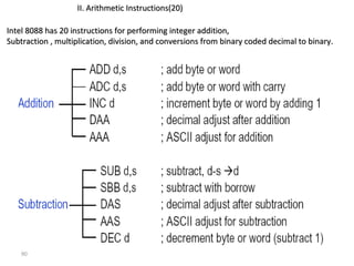
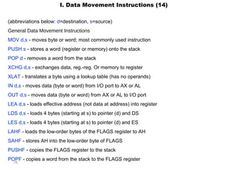
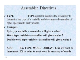
![92
AAddddiittiioonn
BBiinnaarryy aaddddiittiioonn ooff ttwwoo bbyytteess oorr ttwwoo wwoorrddss aarree ppeerrffoorrmmeedd uussiinngg::
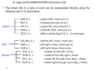
AADDDD dd,,ss
AADDDD aaddddss bbyytteess oorr wwoorrddss iinn dd aanndd ss aanndd ssttoorreess rreessuulltt iinn dd..
TThhee ooppeerraannddss dd aanndd ss ccaann uussee tthhee ssaammee aaddddrreessssiinngg mmooddeess aass iinn MMOOVV..
AAddddiittiioonn ooff ddoouubbllee--wwoorrdd iiss aacchhiieevveedd bbyy uussiinngg tthhee ccaarrrryy bbiitt iinn tthhee FFLLAAGGSS rreeggiisstteerr.. TThhee
iinnssttrruuccttiioonn
AADDCC dd,,ss
aauuttoommaattiiccaallllyy iinncclluuddeess tthhee ccaarrrryy ffllaagg,, aanndd iiss uusseedd ttoo aadddd tthhee mmoorree ssiiggnniiffiiccaanntt wwoorrdd iinn aa
ddoouubbllee--wwoorrdd aaddddiittiioonn..
Addition
Example: addition of two double words stored at [x] and [y]
MOV AX, [x] ; Loads AX with the word stored at location [x]
MOV DX, [x+2] ; Loads the high order word
ADD AX, [y] ; Adds the low order word at [y]
ADC DX, [y+2] ; Add including the carry from the low order words](https://image.slidesharecdn.com/unit-1-mpi-140822043125-phpapp01/85/MPMC-Unit-1-92-320.jpg)
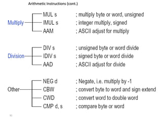
![93
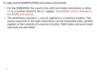
AAddddiittiioonn ((ccoonntt..))
EExxaammppllee:: aaddddiittiioonn ooff ttwwoo ddoouubbllee wwoorrddss ssttoorreedd aatt [[xx]] aanndd [[yy]]
AAddddiittiioonn ooff bbiinnaarryy ccooddeedd ddeecciimmaall nnuummbbeerrss ((BBCCDD)) ccaann bbee ppeerrffoorrmmeedd bbyy uussiinngg AADDDD
oorr AADDCC ffoolllloowweedd bbyy tthhee DDAAAA iinnssttrruuccttiioonn ttoo ccoonnvveerrtt tthhee
nnuummbbeerr iinn rreeggiisstteerr AALL ttoo aa BBCCDD rreepprreesseennttaattiioonn.. ((sseeee eexxaammppllee))
AAddddiittiioonn ooff nnuummbbeerrss iinn tthheeiirr AASSCCIIII ffoorrmm iiss aacchhiieevveedd bbyy uussiinngg AAAAAA ((aasscciiii aaddjjuusstt
aafftteerr aaddddiittiioonn))..](https://image.slidesharecdn.com/unit-1-mpi-140822043125-phpapp01/85/MPMC-Unit-1-93-320.jpg)
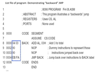


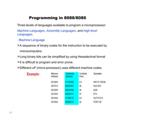
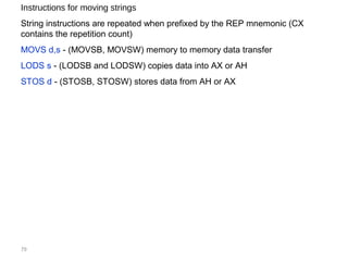
![154
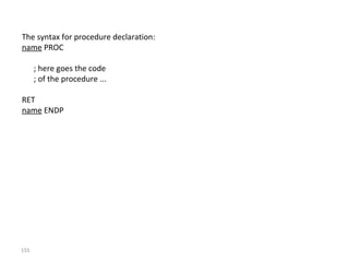
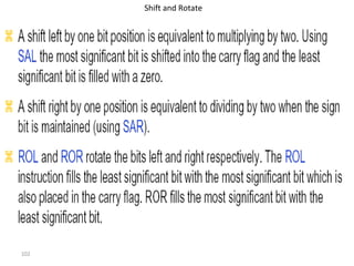
Macro definition:
name MACRO [parameters,...]
<instructions>
ENDM
MyMacro MACRO p1, p2, p3
MOV AX, p1
MOV BX, p2
MOV CX, p3
ENDM
ORG 100h
MyMacro 1, 2, 3
MyMacro 4, 5, DX
RET](https://image.slidesharecdn.com/unit-1-mpi-140822043125-phpapp01/85/MPMC-Unit-1-153-320.jpg)