Downloaded 189 times


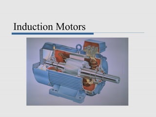

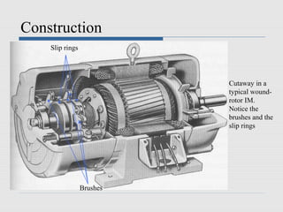

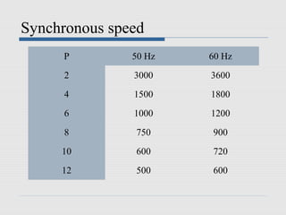
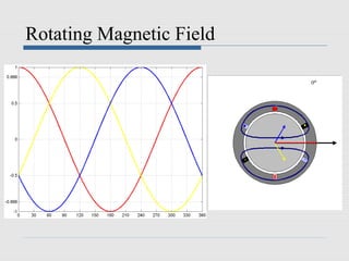

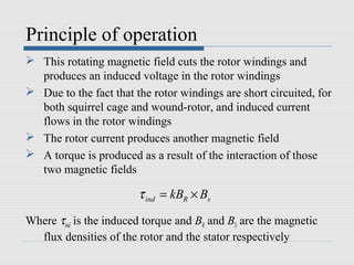

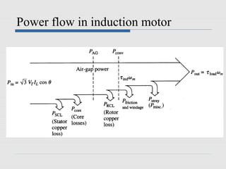


This document provides information about induction motors. It describes the basic construction of an induction motor, including its stator and squirrel cage or wound rotor. It explains how a rotating magnetic field is produced from the three-phase stator windings and how this induces a voltage and current in the rotor. It defines key terms like synchronous speed and slip. It also presents the equivalent circuit model of an induction motor and discusses speed control methods and power losses in induction machines.


