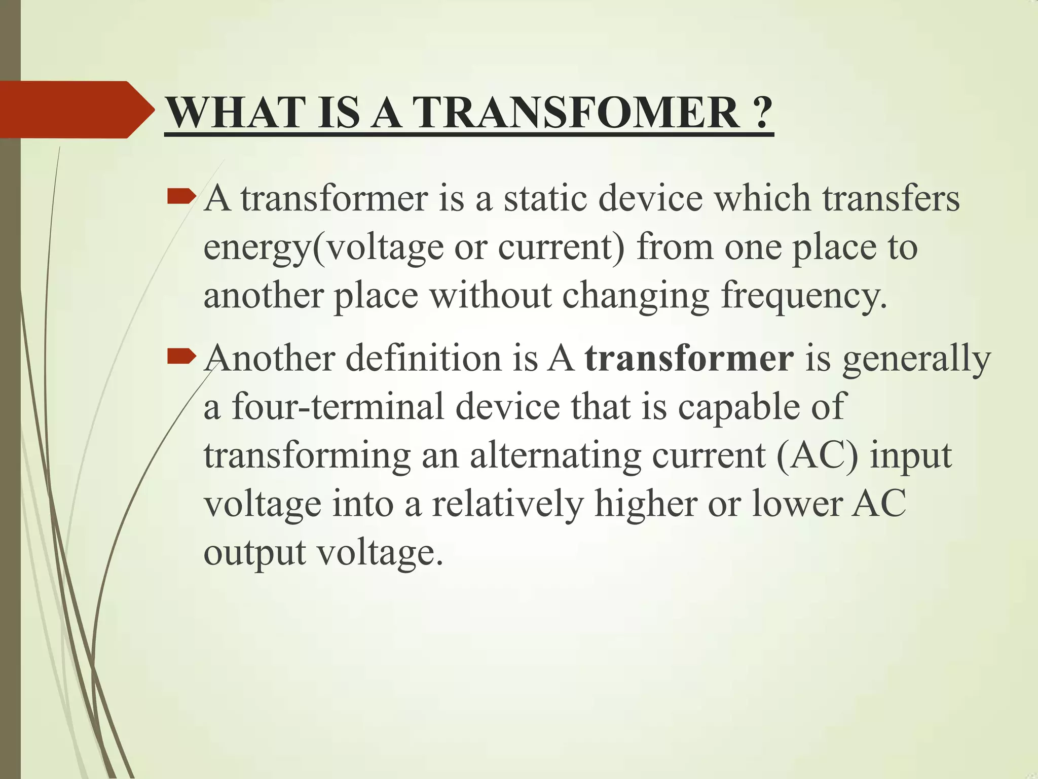
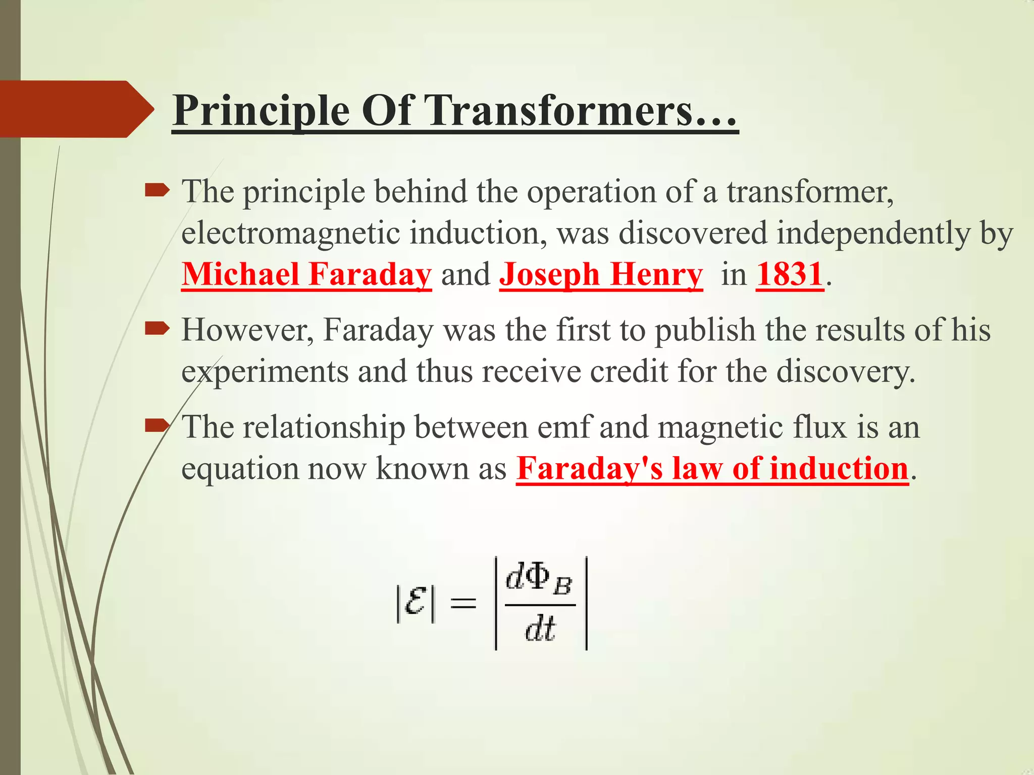
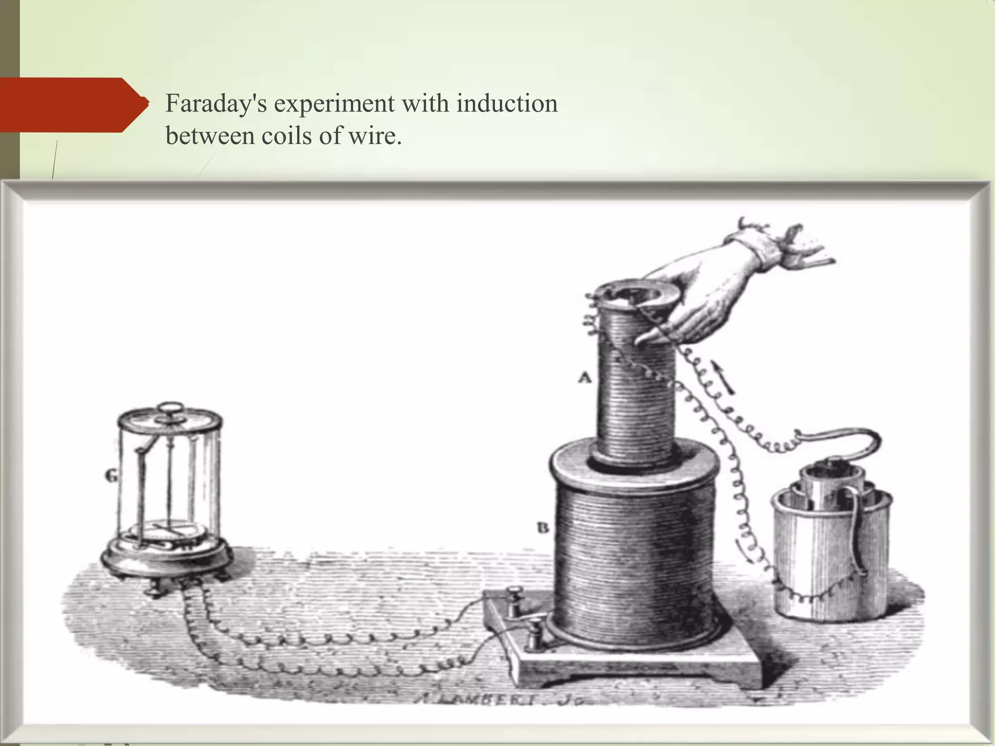
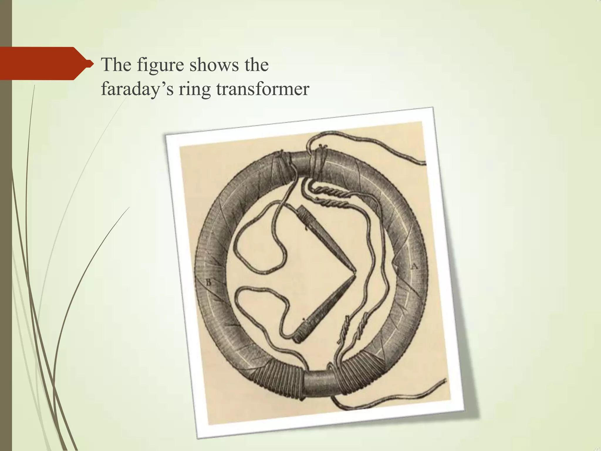
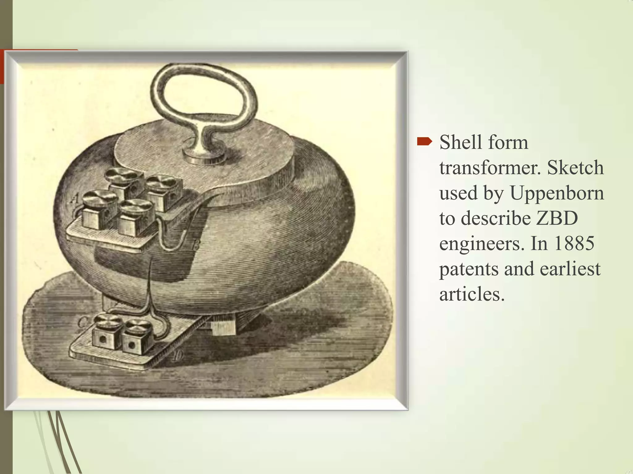
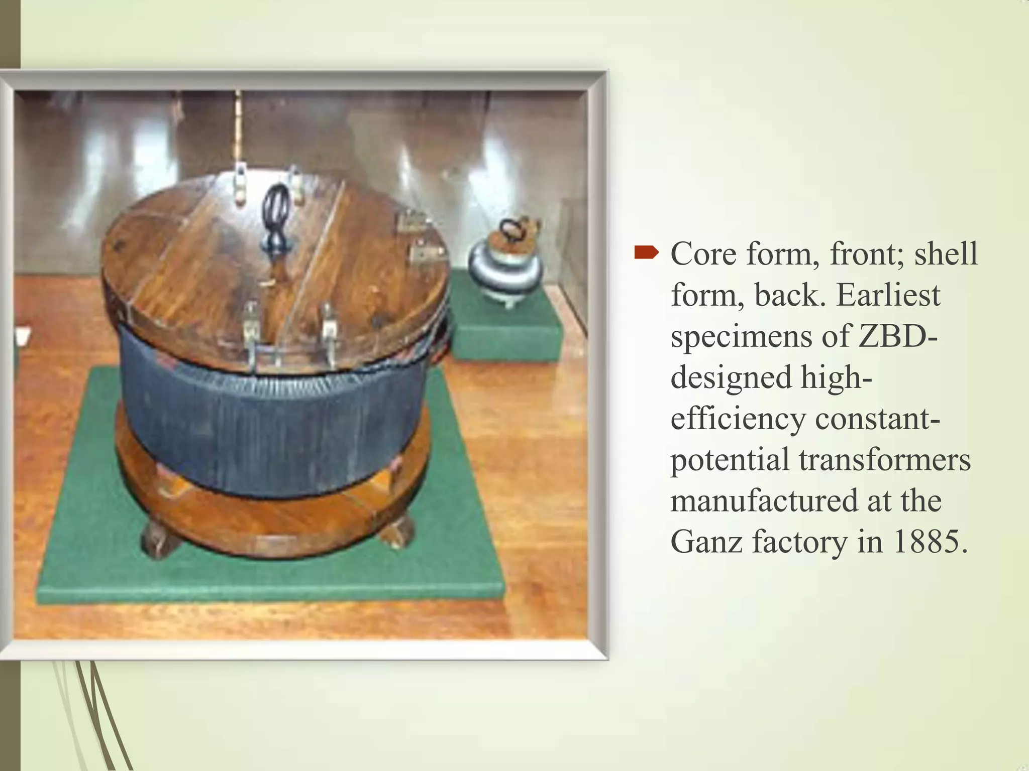
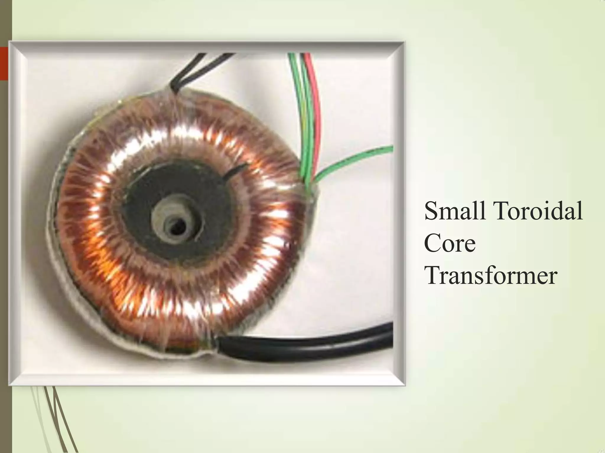
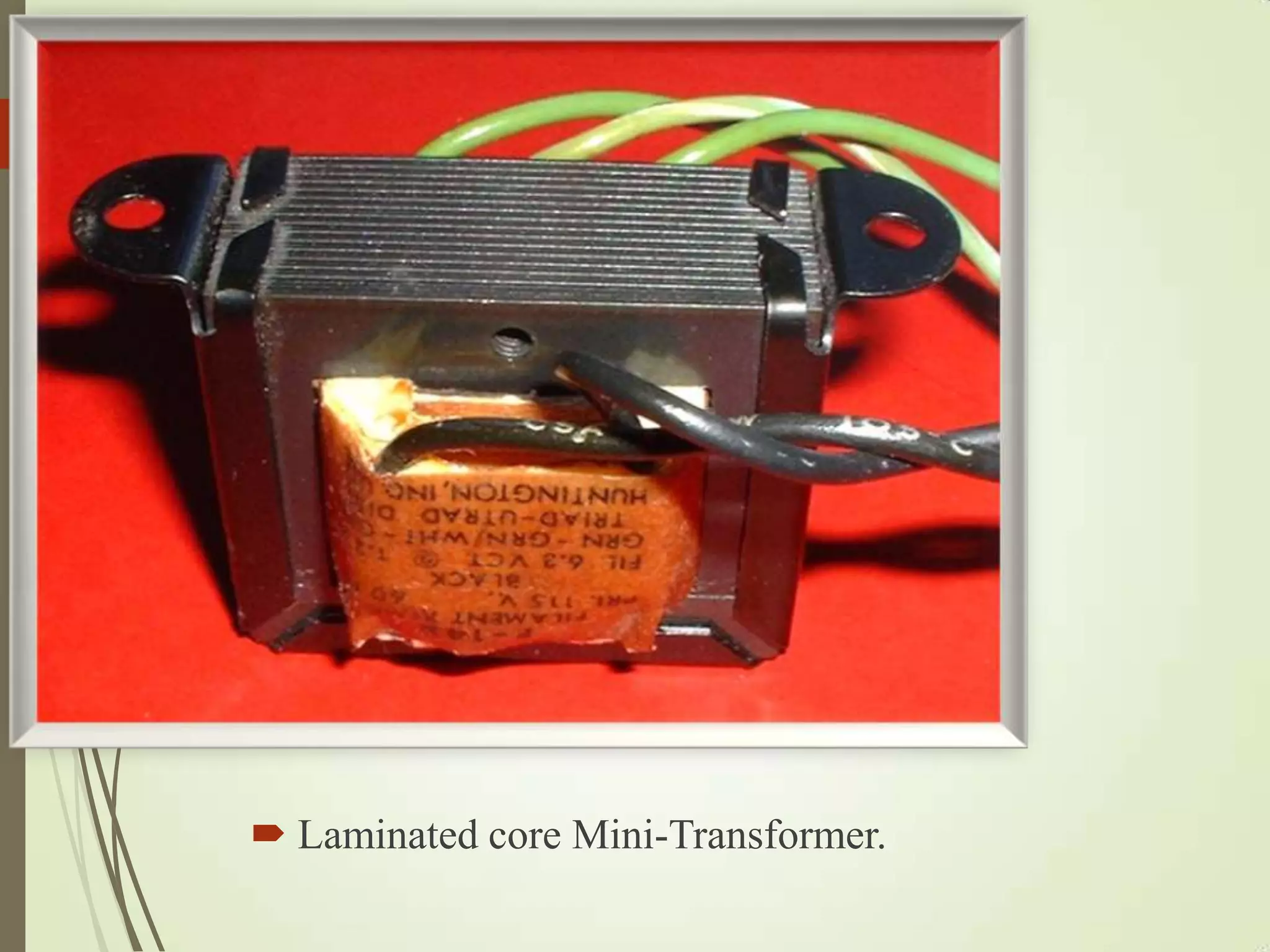
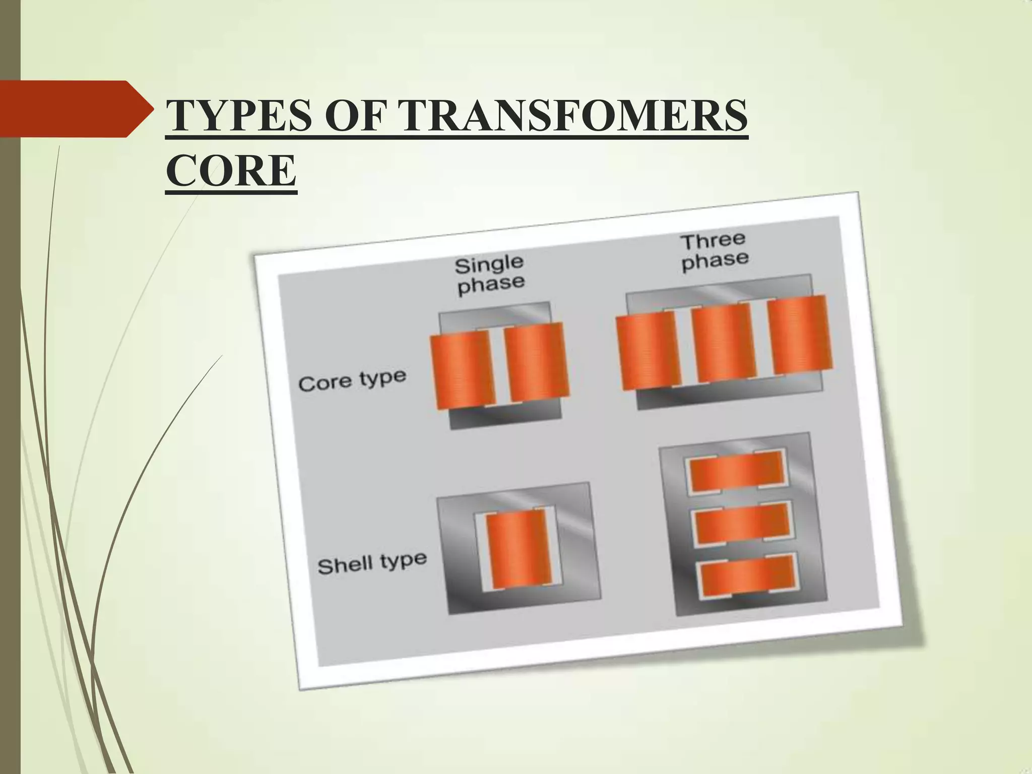
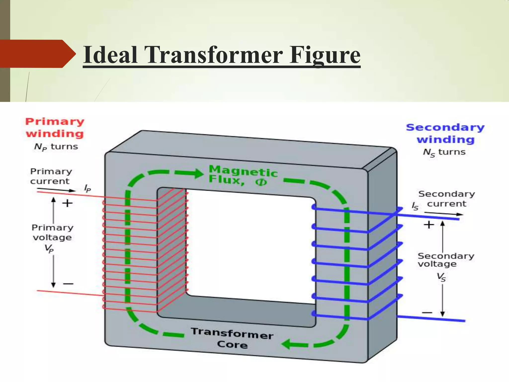
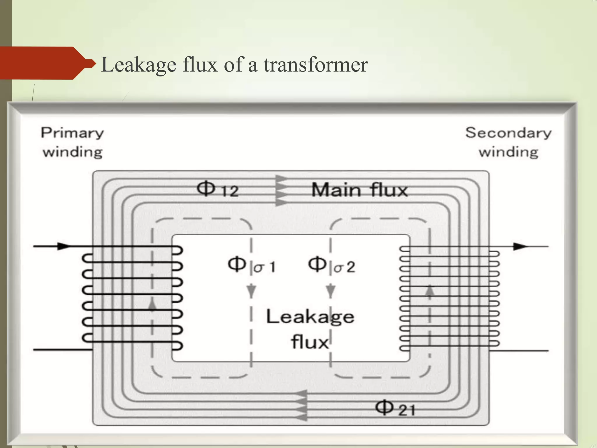
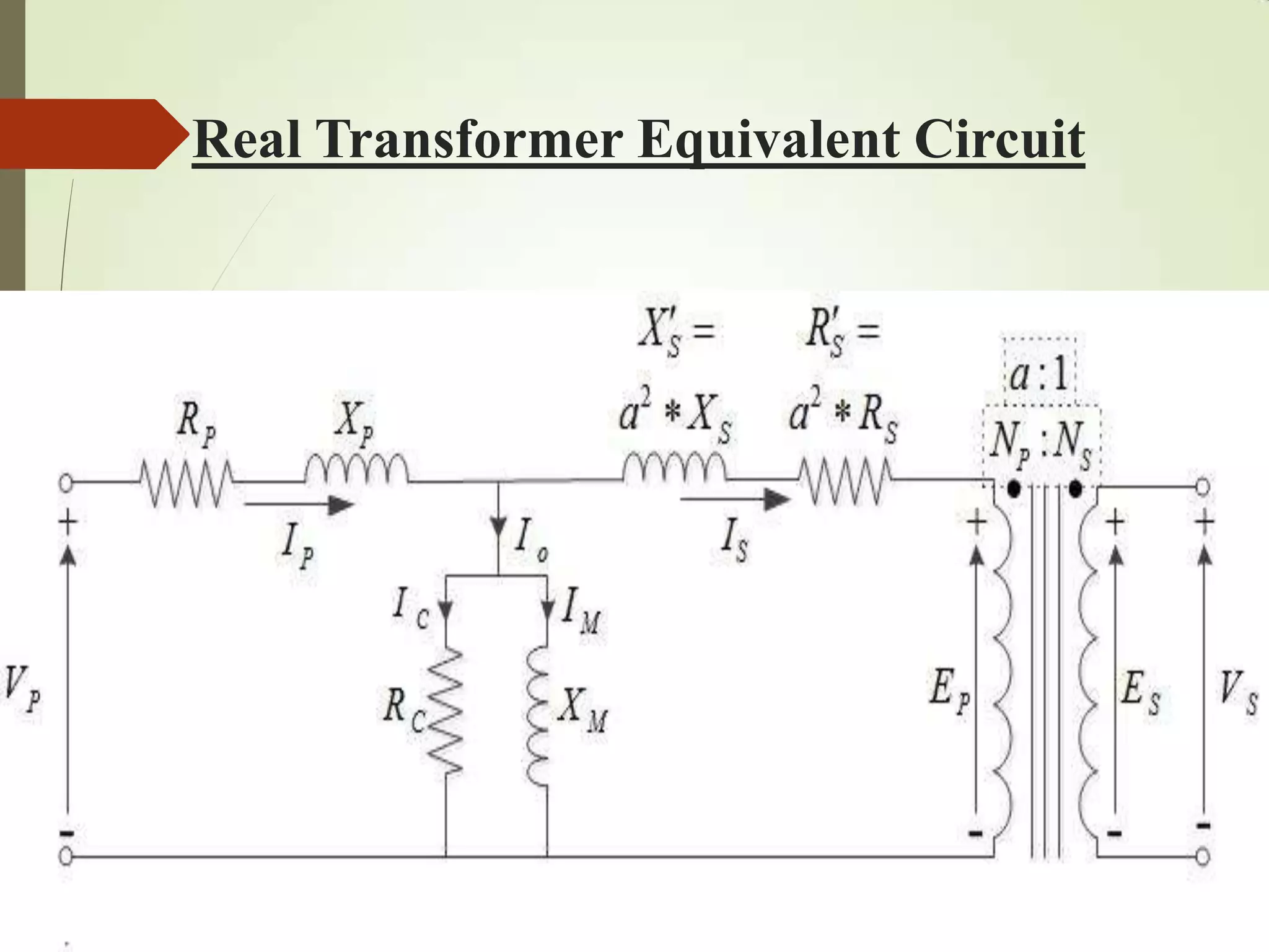
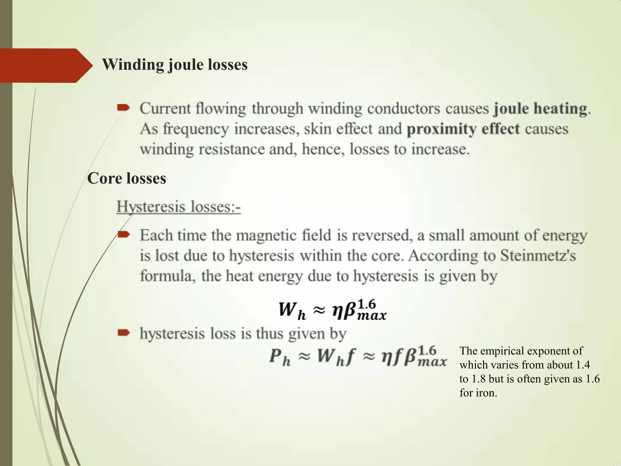
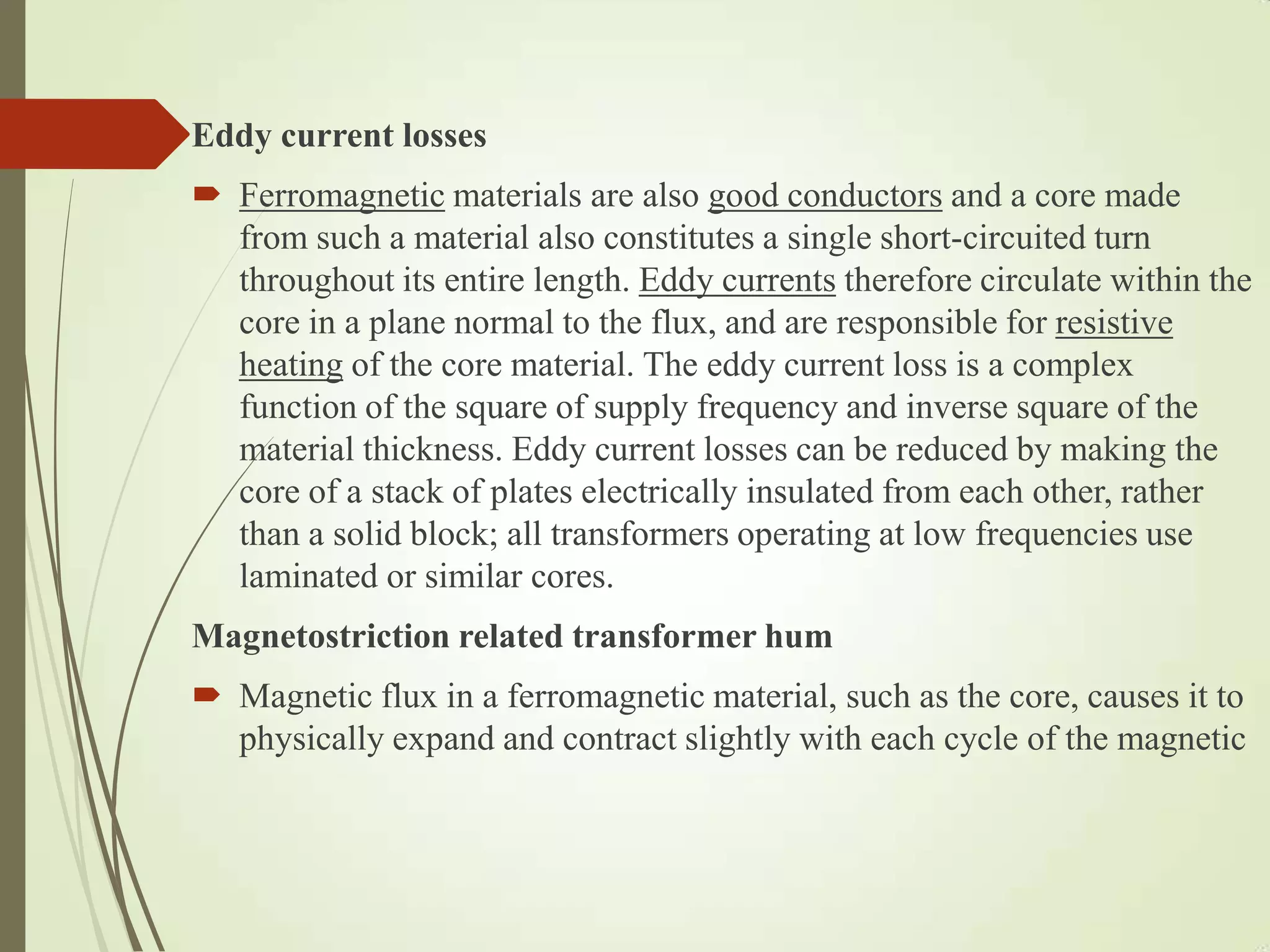
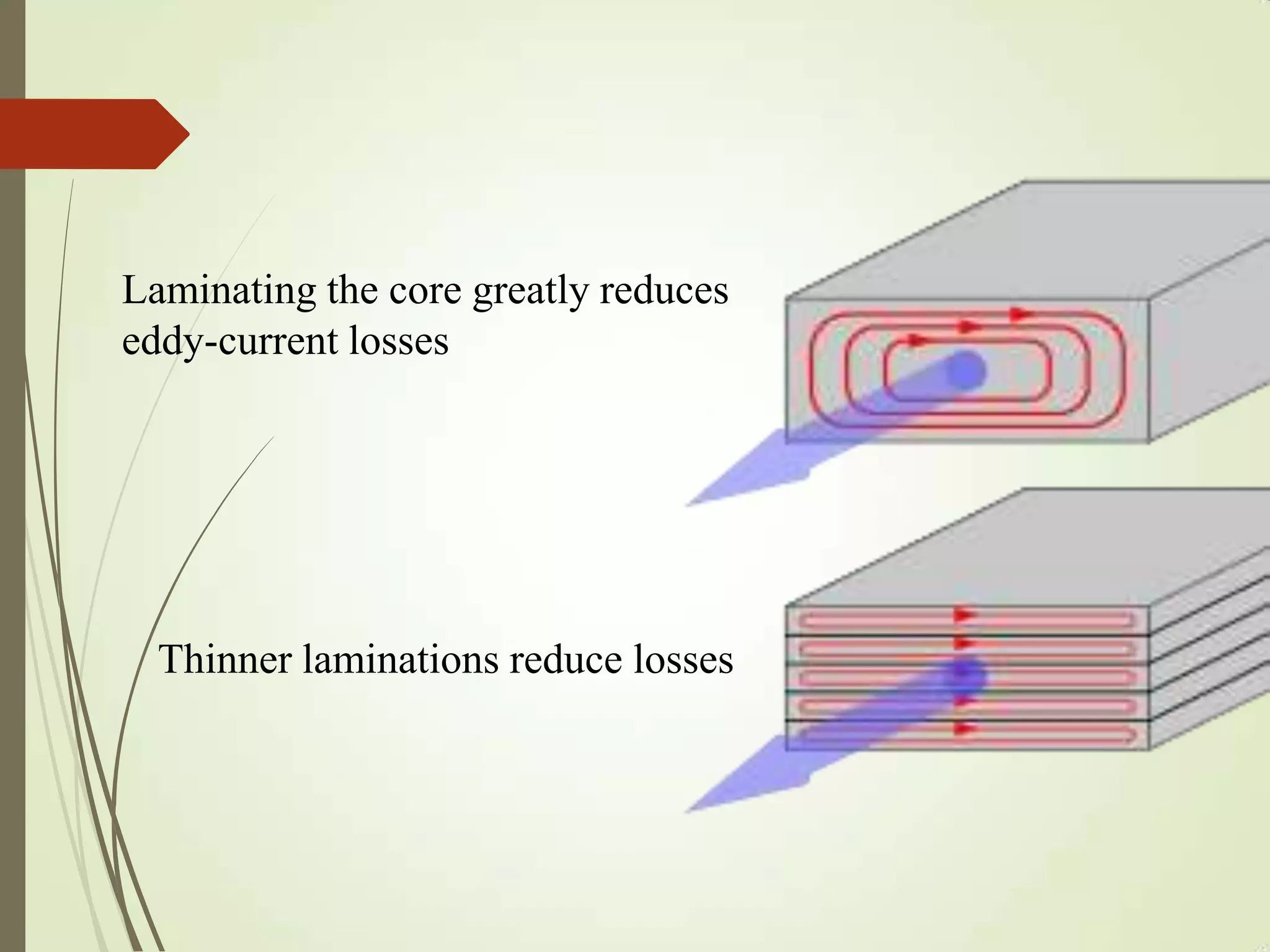
TRANSFOMERS
By
A.S.Krishna
WHAT IS A TRANSFOMER ?
A transformer is a static device which transfers
energy(voltage or current) from one place to
another place without changing frequency.
Another definition is A transformer is generally
a four-terminal device that is capable of
transforming an alternating current (AC) input
voltage into a relatively higher or lower AC
output voltage.
Principle Of Transformers…
 The principle behind the operation of a transformer,
electromagnetic induction, was discovered independently by
Michael Faraday and Joseph Henry in 1831.
 However, Faraday was the first to publish the results of his
experiments and thus receive credit for the discovery.
 The relationship between emf and magnetic flux is an
equation now known as Faraday's law of induction.
Invention Of Transformers…
 The invention of transformers during the late 1800s
allowed for longer-distance, cheaper, and more energy
efficient transmission, distribution, and utilization of
electrical energy.
 Transformers today are designed on the principles
discovered by the three engineers.
 They also popularized the word 'transformer' to describe
a device for altering the emf of an electric current although
the term had already been in use by 1882.
 In 1886, the ZBD engineers designed, and the Ganz
factory supplied electrical equipment for, the world's first
power station that used AC generators to power a parallel
connected common electrical network, the steam-powered
Rome-Cerchi power plant.
 In 1889, Russian-born engineer Mikhail Dolivo-
Dobrovolsky developed the first three-phase transformer at
the Allgemeine Elektricitäts-Gesellschaft ('General
Electricity Company') in Germany.
 In 1891, Nikola Tesla invented the Tesla coil, an air-cored,
dual-tuned resonant transformer for generating very high
voltages at high frequency.
ZBD Engineers Team
The ZBD team consisted of Károly
Zipernowsky, Ottó Bláthy and Miksa Déri
Developments In Transformers…
 Faraday performed the first experiments on induction
between coils of wire, including winding a pair of coils
around an iron ring, thus creating the first toroidal closed-
core (or) ring transformer.
 Later the ZBD engineers are develop the transformers and
also many other engineers are develop the new models of
transformers which we are seeing now-a-days .
 And the below given figures are shows the developments
occur in the transformers in further days of inventions.
 Faraday's experiment with induction
between coils of wire.
 The figure shows the
faraday’s ring transformer
 Shell form
transformer. Sketch
used by Uppenborn
to describe ZBD
engineers. In 1885
patents and earliest
articles.
 Core form, front; shell
form, back. Earliest
specimens of ZBD-
designed high-
efficiency constant-
potential transformers
manufactured at the
Ganz factory in 1885.
Small Toroidal
Core
Transformer
 Laminated core Mini-Transformer.
 Cutaway view of liquid-immersed
construction transformer. The
conservator (reservoir) at top
provides liquid-to-atmosphere
isolation as coolant level and
temperature changes. The walls and
fins provide required heat dissipation
balance.
TYPES OF TRANSFOMERS
CORE
 Pole-mounted distribution
transformer with center-
tapped secondary winding used
to provide 'split-phase' power
for residential and light
commercial service, which in
North America is typically rated
120/240 volt.
Ideal Transformer
 The ideal condition assumptions are:::---
 The windings of the transformer have negligible resistance, so
RP= RS= 0, where RP represents the resistance of the primary
winding and RS represents the resistance of the secondary winding.
Thus, there is no copper loss in the winding, and hence no voltage
drop.
 Flux is confined within the core. Therefore, it is the same flux that
links both the windings.
 Permeability of the core is infinitely high which implies that zero
mmf (current) is required to set up the flux and that the flux in the
core due to the primary winding must be equal and opposite to the
flux due to the secondary winding.
 The core does not incur any hysteresis or eddy current loss.
Hence, no core losses.
Ideal Transformer Circuit Diagram
The ideal transformer induces
secondary voltage ES =VS as a
proportion of the primary voltage
VP = EP and respective winding
turns as given by the equation.
Ideal Transformer Figure
Real transformer deviations from ideal
 The ideal model neglects the following basic linear aspects in real
transformers:
Core losses collectively called magnetizing current losses consisting of:--
•Hysteresis losses due to nonlinear application of the voltage
applied in the transformer core
•Eddy current losses due to joule heating in core are proportional
to the square of the transformer's applied voltage.
Whereas the ideal windings have no impedance, the windings in a real
transformer have finite non-zero impedances in the form of:
•Joule losses due to resistance in the primary and secondary
windings.
•Leakage flux that escapes from the core and passes through one
winding only resulting in primary and secondary reactive
impedance.
Leakage flux of a transformer
Real Transformer Equivalent Circuit
ENERGY LOSSES
 Contrarily, a 'practical' (or 'real') transformer does experience energy
losses (its typically 95 to 99% efficient) due to a variety of loss
mechanisms, including winding resistance, winding
capacitance, leakage flux, core losses, and hysteresis loss.
 Larger transformers are generally more efficient, and those rated for
electricity distribution usually perform better than 98%.
 Experimental transformers using superconducting windings achieve
efficiencies of 99.85%.
 As transformer losses vary with load, it is often useful to express
these losses in terms of no-load loss, full-load loss, half-load
loss, and so on. Hysteresis and eddy current losses are constant at
all loads and dominate overwhelmingly at no-load, variable winding
joule losses dominating increasingly as load increases.
Winding joule losses

Core losses
The empirical exponent of
which varies from about 1.4
to 1.8 but is often given as 1.6
for iron.
Eddy current losses
 Ferromagnetic materials are also good conductors and a core made
from such a material also constitutes a single short-circuited turn
throughout its entire length. Eddy currents therefore circulate within the
core in a plane normal to the flux, and are responsible for resistive
heating of the core material. The eddy current loss is a complex
function of the square of supply frequency and inverse square of the
material thickness. Eddy current losses can be reduced by making the
core of a stack of plates electrically insulated from each other, rather
than a solid block; all transformers operating at low frequencies use
laminated or similar cores.
Magnetostriction related transformer hum
 Magnetic flux in a ferromagnetic material, such as the core, causes it to
physically expand and contract slightly with each cycle of the magnetic
 field, an effect known as magnetostriction, the frictional
energy of which produces an audible noise known as
mains hum or transformer hum. This transformer hum is
especially objectionable in transformers supplied at power
frequencies and in high-frequency flyback transformers
associated with PAL system CRTs.
Stray losses
 Leakage inductance is by itself largely lossless, since
energy supplied to its magnetic fields is returned to the
supply with the next half-cycle. However, any leakage
flux that intercepts nearby conductive materials such as
the transformer's support structure will give rise to eddy
currents and be converted to heat. There are also radiative
losses due to the oscillating magnetic field but these are
usually small.
Mechanical vibration and audible noise transmission
 In addition to magnetostriction, the alternating magnetic
field causes fluctuating forces between the primary and
secondary windings. This energy incites vibration
transmission in interconnected metalwork, thus amplifying
audible transformer hum.
Why laminating cores?....
 Transformers for use at power or audio frequencies
typically have cores made of high permeability silicon
steel. These laminations are used to reduce the eddy
current losses.
 Thinner laminations reduce losses. Thin laminations are
generally used on high-frequency transformers, with
some of very thin steel laminations able to operate up to
10 kHz.
 Distribution transformers can achieve low no-load losses
by using cores made with low-loss high-permeability
silicon steel or amorphous (non-crystalline) metal alloy.
The higher initial cost of the core material is offset over
the life of the transformer by its lower losses at light
load.
Thinner laminations reduce losses
Laminating the core greatly reduces
eddy-current losses
Cooling of transformers…
 Small dry-type and liquid-immersed transformers are often self-cooled by
natural convection and radiation heat dissipation. As power ratings
increase, transformers are often cooled by forced-air cooling, forced-oil
cooling, water-cooling, or combinations of these. Large transformers are
filled with transformer oil that both cools and insulates the windings.
 Transformer oil is a highly refined mineral oil that cools the windings and
insulation by circulating within the transformer tank. The mineral oil and
paper insulation system has been extensively studied and used for more
than 100 years.
 It is estimated that 50% of power transformers will survive 50 years of
use, that the average age of failure of power transformers is about 10 to 15
years, and that about 30% of power transformer failures are due to
insulation and overloading failures.
 Some transformers, instead of being liquid-filled, have their
windings enclosed in sealed, pressurized tanks and cooled by
nitrogen or sulfur hexafluoride gas.
 Experimental power transformers in the 500-to-1,000 kVA
range have been built with liquid nitrogen or helium cooled
superconducting windings, which eliminates winding
losses without affecting core losses.
 Larger transformers are provided with high-voltage insulated
bushings made of polymers or porcelain. A large bushing
can be a complex structure since it must provide careful
control of the electric field gradient without letting the
transformer leak oil.
Different types of transformers…
 A wide variety of transformer designs are used for different
applications, though they share several common features. Important
common transformer types include:
 Autotransformer: Transformer in which part of the winding is
common to both primary and secondary circuits.
 Capacitor voltage transformer: Transformer in which capacitor
divider is used to reduce high voltage before application to the
primary winding.
 Distribution transformer, power transformer: International standards
make a distinction in terms of distribution transformers being used to
distribute energy from transmission lines and networks for local
consumption and power transformers being used to transfer electric
energy between the generator and distribution primary circuits.
 Phase angle regulating transformer: A specialised transformer used to
control the flow of real power on three-phase electricity transmission
networks.
 Scott-T transformer: Transformer used for phase transformation from
three-phase to two-phase and vice versa.
 Polyphase transformer: Any transformer with more than one phase.
 Grounding transformer: Transformer used for grounding three-phase
circuits to create a neutral in a three wire system, using a wye-delta
transformer, or more commonly, a zigzag grounding winding.
 Leakage transformer: Transformer that has loosely coupled windings.
 Resonant transformer: Transformer that uses resonance to generate a
high secondary voltage.
 Audio transformer: Transformer used in audio equipment.
 Output transformer: Transformer used to match the output
of a valve amplifier to its load.
 Instrument transformer: Potential or current transformer
used to accurately and safely represent voltage, current or
phase position of high voltage or high power circuits.
Applications…
 Signal and audio transformers are used to couple stages
of amplifiers and to match devices such as microphones
and record players to the input of amplifiers.
 Audio transformers allowed telephone circuits to carry
on a two-way conversation over a single pair of wires.
 A balun transformer converts a signal that is referenced
to ground to a signal that has balanced voltages to
ground, such as between external cables and internal
circuits.
 And also we have many more applications of
transformers like chargers and so on.
Electrical Transfomers

Electrical Transfomers

  • 1.
  • 2.
    WHAT IS ATRANSFOMER ? A transformer is a static device which transfers energy(voltage or current) from one place to another place without changing frequency. Another definition is A transformer is generally a four-terminal device that is capable of transforming an alternating current (AC) input voltage into a relatively higher or lower AC output voltage.
  • 3.
    Principle Of Transformers… The principle behind the operation of a transformer, electromagnetic induction, was discovered independently by Michael Faraday and Joseph Henry in 1831.  However, Faraday was the first to publish the results of his experiments and thus receive credit for the discovery.  The relationship between emf and magnetic flux is an equation now known as Faraday's law of induction.
  • 4.
    Invention Of Transformers… The invention of transformers during the late 1800s allowed for longer-distance, cheaper, and more energy efficient transmission, distribution, and utilization of electrical energy.  Transformers today are designed on the principles discovered by the three engineers.  They also popularized the word 'transformer' to describe a device for altering the emf of an electric current although the term had already been in use by 1882.  In 1886, the ZBD engineers designed, and the Ganz factory supplied electrical equipment for, the world's first power station that used AC generators to power a parallel connected common electrical network, the steam-powered Rome-Cerchi power plant.
  • 5.
     In 1889,Russian-born engineer Mikhail Dolivo- Dobrovolsky developed the first three-phase transformer at the Allgemeine Elektricitäts-Gesellschaft ('General Electricity Company') in Germany.  In 1891, Nikola Tesla invented the Tesla coil, an air-cored, dual-tuned resonant transformer for generating very high voltages at high frequency.
  • 6.
    ZBD Engineers Team TheZBD team consisted of Károly Zipernowsky, Ottó Bláthy and Miksa Déri
  • 7.
    Developments In Transformers… Faraday performed the first experiments on induction between coils of wire, including winding a pair of coils around an iron ring, thus creating the first toroidal closed- core (or) ring transformer.  Later the ZBD engineers are develop the transformers and also many other engineers are develop the new models of transformers which we are seeing now-a-days .  And the below given figures are shows the developments occur in the transformers in further days of inventions.
  • 8.
     Faraday's experimentwith induction between coils of wire.
  • 9.
     The figureshows the faraday’s ring transformer
  • 10.
     Shell form transformer.Sketch used by Uppenborn to describe ZBD engineers. In 1885 patents and earliest articles.
  • 11.
     Core form,front; shell form, back. Earliest specimens of ZBD- designed high- efficiency constant- potential transformers manufactured at the Ganz factory in 1885.
  • 12.
  • 13.
     Laminated coreMini-Transformer.
  • 14.
     Cutaway viewof liquid-immersed construction transformer. The conservator (reservoir) at top provides liquid-to-atmosphere isolation as coolant level and temperature changes. The walls and fins provide required heat dissipation balance.
  • 15.
  • 16.
     Pole-mounted distribution transformerwith center- tapped secondary winding used to provide 'split-phase' power for residential and light commercial service, which in North America is typically rated 120/240 volt.
  • 17.
    Ideal Transformer  Theideal condition assumptions are:::---  The windings of the transformer have negligible resistance, so RP= RS= 0, where RP represents the resistance of the primary winding and RS represents the resistance of the secondary winding. Thus, there is no copper loss in the winding, and hence no voltage drop.  Flux is confined within the core. Therefore, it is the same flux that links both the windings.  Permeability of the core is infinitely high which implies that zero mmf (current) is required to set up the flux and that the flux in the core due to the primary winding must be equal and opposite to the flux due to the secondary winding.  The core does not incur any hysteresis or eddy current loss. Hence, no core losses.
  • 18.
    Ideal Transformer CircuitDiagram The ideal transformer induces secondary voltage ES =VS as a proportion of the primary voltage VP = EP and respective winding turns as given by the equation.
  • 19.
  • 20.
    Real transformer deviationsfrom ideal  The ideal model neglects the following basic linear aspects in real transformers: Core losses collectively called magnetizing current losses consisting of:-- •Hysteresis losses due to nonlinear application of the voltage applied in the transformer core •Eddy current losses due to joule heating in core are proportional to the square of the transformer's applied voltage. Whereas the ideal windings have no impedance, the windings in a real transformer have finite non-zero impedances in the form of: •Joule losses due to resistance in the primary and secondary windings. •Leakage flux that escapes from the core and passes through one winding only resulting in primary and secondary reactive impedance.
  • 21.
    Leakage flux ofa transformer
  • 22.
  • 23.
    ENERGY LOSSES  Contrarily,a 'practical' (or 'real') transformer does experience energy losses (its typically 95 to 99% efficient) due to a variety of loss mechanisms, including winding resistance, winding capacitance, leakage flux, core losses, and hysteresis loss.  Larger transformers are generally more efficient, and those rated for electricity distribution usually perform better than 98%.  Experimental transformers using superconducting windings achieve efficiencies of 99.85%.  As transformer losses vary with load, it is often useful to express these losses in terms of no-load loss, full-load loss, half-load loss, and so on. Hysteresis and eddy current losses are constant at all loads and dominate overwhelmingly at no-load, variable winding joule losses dominating increasingly as load increases.
  • 24.
    Winding joule losses  Corelosses The empirical exponent of which varies from about 1.4 to 1.8 but is often given as 1.6 for iron.
  • 25.
    Eddy current losses Ferromagnetic materials are also good conductors and a core made from such a material also constitutes a single short-circuited turn throughout its entire length. Eddy currents therefore circulate within the core in a plane normal to the flux, and are responsible for resistive heating of the core material. The eddy current loss is a complex function of the square of supply frequency and inverse square of the material thickness. Eddy current losses can be reduced by making the core of a stack of plates electrically insulated from each other, rather than a solid block; all transformers operating at low frequencies use laminated or similar cores. Magnetostriction related transformer hum  Magnetic flux in a ferromagnetic material, such as the core, causes it to physically expand and contract slightly with each cycle of the magnetic
  • 26.
     field, aneffect known as magnetostriction, the frictional energy of which produces an audible noise known as mains hum or transformer hum. This transformer hum is especially objectionable in transformers supplied at power frequencies and in high-frequency flyback transformers associated with PAL system CRTs. Stray losses  Leakage inductance is by itself largely lossless, since energy supplied to its magnetic fields is returned to the supply with the next half-cycle. However, any leakage flux that intercepts nearby conductive materials such as the transformer's support structure will give rise to eddy currents and be converted to heat. There are also radiative losses due to the oscillating magnetic field but these are usually small.
  • 27.
    Mechanical vibration andaudible noise transmission  In addition to magnetostriction, the alternating magnetic field causes fluctuating forces between the primary and secondary windings. This energy incites vibration transmission in interconnected metalwork, thus amplifying audible transformer hum.
  • 28.
    Why laminating cores?.... Transformers for use at power or audio frequencies typically have cores made of high permeability silicon steel. These laminations are used to reduce the eddy current losses.  Thinner laminations reduce losses. Thin laminations are generally used on high-frequency transformers, with some of very thin steel laminations able to operate up to 10 kHz.  Distribution transformers can achieve low no-load losses by using cores made with low-loss high-permeability silicon steel or amorphous (non-crystalline) metal alloy. The higher initial cost of the core material is offset over the life of the transformer by its lower losses at light load.
  • 29.
    Thinner laminations reducelosses Laminating the core greatly reduces eddy-current losses
  • 30.
    Cooling of transformers… Small dry-type and liquid-immersed transformers are often self-cooled by natural convection and radiation heat dissipation. As power ratings increase, transformers are often cooled by forced-air cooling, forced-oil cooling, water-cooling, or combinations of these. Large transformers are filled with transformer oil that both cools and insulates the windings.  Transformer oil is a highly refined mineral oil that cools the windings and insulation by circulating within the transformer tank. The mineral oil and paper insulation system has been extensively studied and used for more than 100 years.  It is estimated that 50% of power transformers will survive 50 years of use, that the average age of failure of power transformers is about 10 to 15 years, and that about 30% of power transformer failures are due to insulation and overloading failures.
  • 31.
     Some transformers,instead of being liquid-filled, have their windings enclosed in sealed, pressurized tanks and cooled by nitrogen or sulfur hexafluoride gas.  Experimental power transformers in the 500-to-1,000 kVA range have been built with liquid nitrogen or helium cooled superconducting windings, which eliminates winding losses without affecting core losses.  Larger transformers are provided with high-voltage insulated bushings made of polymers or porcelain. A large bushing can be a complex structure since it must provide careful control of the electric field gradient without letting the transformer leak oil.
  • 32.
    Different types oftransformers…  A wide variety of transformer designs are used for different applications, though they share several common features. Important common transformer types include:  Autotransformer: Transformer in which part of the winding is common to both primary and secondary circuits.  Capacitor voltage transformer: Transformer in which capacitor divider is used to reduce high voltage before application to the primary winding.  Distribution transformer, power transformer: International standards make a distinction in terms of distribution transformers being used to distribute energy from transmission lines and networks for local consumption and power transformers being used to transfer electric energy between the generator and distribution primary circuits.
  • 33.
     Phase angleregulating transformer: A specialised transformer used to control the flow of real power on three-phase electricity transmission networks.  Scott-T transformer: Transformer used for phase transformation from three-phase to two-phase and vice versa.  Polyphase transformer: Any transformer with more than one phase.  Grounding transformer: Transformer used for grounding three-phase circuits to create a neutral in a three wire system, using a wye-delta transformer, or more commonly, a zigzag grounding winding.  Leakage transformer: Transformer that has loosely coupled windings.  Resonant transformer: Transformer that uses resonance to generate a high secondary voltage.  Audio transformer: Transformer used in audio equipment.
  • 34.
     Output transformer:Transformer used to match the output of a valve amplifier to its load.  Instrument transformer: Potential or current transformer used to accurately and safely represent voltage, current or phase position of high voltage or high power circuits.
  • 35.
    Applications…  Signal andaudio transformers are used to couple stages of amplifiers and to match devices such as microphones and record players to the input of amplifiers.  Audio transformers allowed telephone circuits to carry on a two-way conversation over a single pair of wires.  A balun transformer converts a signal that is referenced to ground to a signal that has balanced voltages to ground, such as between external cables and internal circuits.  And also we have many more applications of transformers like chargers and so on.