Downloaded 168 times
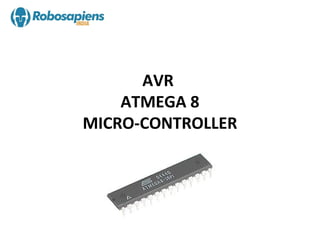


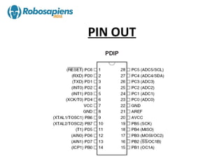


The document provides an overview of the ATmega8 microcontroller, which is an 8-bit microcontroller based on the AVR RISC architecture. It can achieve throughput of up to 1 MIPS per MHz. The ATmega8 uses a Harvard architecture that separates program and data memories and buses. It has features such as 8K bytes of flash memory, 512 bytes of EEPROM, 1K byte of RAM, and three 8-bit I/O ports (Ports B, C, and D).