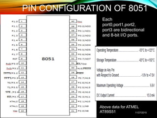
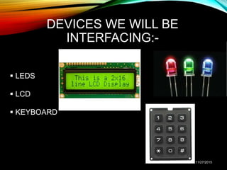
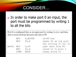
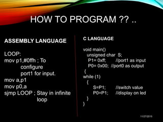
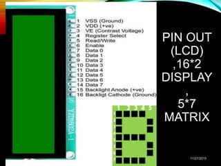
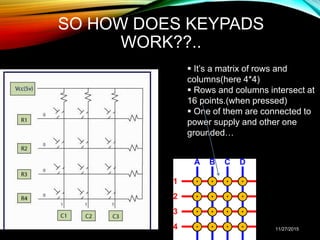
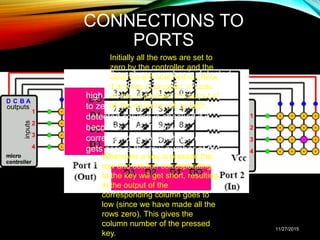
THE 8051
MICROCONTROLLER :
I/O INTERFACING
Presented by:-
Abhinav Shubham(131046)
&
Tanmay Kapoor(131053)
11/27/2015
TOPICS OF
DISCUSSION:-
What is IO interfacing?
Recapitulation of PIN Configuration of 8051
Devices to be interfaced
How they are interfaced?
Queries…
11/27/2015
WHAT IS IO INTERFACING
 Input-output interface provides a method for transferring information between
internal storage and external I/O devices.
 Peripherals connected to a microcontroller need special communication links
for interfacing them with the CPU. The purpose of the communication link is to
resolve the differences that exist between the CPU and each peripheral.
The major differences are:
Peripherals are electromechanical and electromagnetic devices and their
manner of operation is different from the operation of the CPU and memory,
which are electronic devices. Therefore, a conversion of signal values may be
required.
The data transfer rate of peripherals is usually slower than the transfer rate of
the CPU, and consequently, a synchronization mechanism may be needed,
etc…..
11/27/2015
PIN CONFIGURATION OF 8051
11/27/2015
Each
port0,port1,port2,
port3 are bidirectional
and 8-bit I/O ports.
Above data for ATMEL
AT89S51
DEVICES WE WILL BE
INTERFACING:-
 LEDS
 LCD
 KEYBOARD
11/27/2015
INTERFACING LEDS
• Connection -Port 0 is connected to eight LEDs,
each of them is connected to 5V through a 330
ohm resistor. Port 1 is connected to a DIP switch
and a 10Kohm resistor
• Condition - Corresponding led should light up
when switch is pressed , i.e. if Switch at P1.0 is
pressed then LED at P0.0 should light up.
11/27/2015
INTERFACING
LEDS(CONTD.)
11/27/2015
CONSIDER…
11/27/2015
HOW TO PROGRAM ?? ..
ASSEMBLY LANGUAGE
LOOP:
mov p1,#0ffh ; To
configure
port1 for input.
mov a,p1
mov p0,a
sjmp LOOP ; Stay in infinite
loop
C LANGUAGE
void main()
unsigned char S;
P1= 0xff; //port1 as input
P0= 0x00; //port0 as output
{
while (1)
{
S=P1; //switch value
P0=P1; //display on led
}
}
11/27/2015
INTERFACING LCD
• LCD is finding widespread use replacing LED
• The declining prices of LCD
• Ability to display numbers, characters and graphics
• Incorporation of a refreshing controller(graphics
controller, e.g. HD44780) within the LCD, there by
relieving the CPU of an additional task.
• LCD is far better than 7 segment display as it has far
better graphics.
• Ease of programming for characters and graphics
11/27/2015
PIN OUT
(LCD)
,16*2
DISPLAY
,
5*7
MATRIX
11/27/2015
11/27/2015
LCD CONNECTIONS
 To send a command :-
 Specify command to
data pins.
 Make R/W=0 (write
operation)
Make RS=0 (select
command register)
Give a H-to-L pulse to
E(enable pin).
 To send data:-
 Write data to data pins
 R/W =0 (write operation)
 Make RS=1 (select data
register)
 Give a H-to-L pulse to
E(enable pin).Data is written
on positive edge of enable
signal.
11/27/2015
ANOTHER ASPECT TO BE TAKEN
CARE OF…. BUSY FLAG(D7-PIN)
• Some delay is needed for LCD to successfully process the
command or data(processing time of lcd).
• So, before data to be written, check if lcd is busy(check the D7-
pin status(if 1 then busy)
• Reading the Busy flag.
• Select command register (RS=0)
• Select read operation (R/W=1)
• Send enable signal (E=1)
• Read the flag
11/27/2015
KEYBOARD
INTERFACING
• Keypad(keyboard) is a widely used input device with lots of
application in our everyday life.
• From a simple telephone to keyboard of a computer, ATM,
electronic lock, elevator, etc., keypad is used to take input
from the user for further processing.
• Keypad is organized as a matrix of switches in rows and
column.
11/27/2015
SO HOW DOES KEYPADS
WORK??..
11/27/2015
 It’s a matrix of rows and
columns(here 4*4)
 Rows and columns intersect at
16 points.(when pressed)
 One of them are connected to
power supply and other one
grounded…
CONNECTIONS TO
PORTS
11/27/2015
Initially all the rows are set to
zero by the controller and the
columns are scanned to check
if any key is pressed. In case
no key is pressed the output of
all the columns will be high.
Whenever a key is pressed the
row and column corresponding
to the key will get short, resulting
in the output of the
corresponding column goes to
low (since we have made all the
rows zero). This gives the
column number of the pressed
key.
Once the column number is detected,
the controller set’s all the rows to
high. Now one by one each row is set
to zero by controller and the earlier
detected column is checked if it
becomes zero. The row
corresponding to which the column
gets zero is the row number of the
digit.
THANK YOU!!!
11/27/2015

8051 io interface

  • 1.
    THE 8051 MICROCONTROLLER : I/OINTERFACING Presented by:- Abhinav Shubham(131046) & Tanmay Kapoor(131053) 11/27/2015
  • 2.
    TOPICS OF DISCUSSION:- What isIO interfacing? Recapitulation of PIN Configuration of 8051 Devices to be interfaced How they are interfaced? Queries… 11/27/2015
  • 3.
    WHAT IS IOINTERFACING  Input-output interface provides a method for transferring information between internal storage and external I/O devices.  Peripherals connected to a microcontroller need special communication links for interfacing them with the CPU. The purpose of the communication link is to resolve the differences that exist between the CPU and each peripheral. The major differences are: Peripherals are electromechanical and electromagnetic devices and their manner of operation is different from the operation of the CPU and memory, which are electronic devices. Therefore, a conversion of signal values may be required. The data transfer rate of peripherals is usually slower than the transfer rate of the CPU, and consequently, a synchronization mechanism may be needed, etc….. 11/27/2015
  • 4.
    PIN CONFIGURATION OF8051 11/27/2015 Each port0,port1,port2, port3 are bidirectional and 8-bit I/O ports. Above data for ATMEL AT89S51
  • 5.
    DEVICES WE WILLBE INTERFACING:-  LEDS  LCD  KEYBOARD 11/27/2015
  • 6.
    INTERFACING LEDS • Connection-Port 0 is connected to eight LEDs, each of them is connected to 5V through a 330 ohm resistor. Port 1 is connected to a DIP switch and a 10Kohm resistor • Condition - Corresponding led should light up when switch is pressed , i.e. if Switch at P1.0 is pressed then LED at P0.0 should light up. 11/27/2015
  • 7.
  • 8.
  • 9.
    HOW TO PROGRAM?? .. ASSEMBLY LANGUAGE LOOP: mov p1,#0ffh ; To configure port1 for input. mov a,p1 mov p0,a sjmp LOOP ; Stay in infinite loop C LANGUAGE void main() unsigned char S; P1= 0xff; //port1 as input P0= 0x00; //port0 as output { while (1) { S=P1; //switch value P0=P1; //display on led } } 11/27/2015
  • 10.
    INTERFACING LCD • LCDis finding widespread use replacing LED • The declining prices of LCD • Ability to display numbers, characters and graphics • Incorporation of a refreshing controller(graphics controller, e.g. HD44780) within the LCD, there by relieving the CPU of an additional task. • LCD is far better than 7 segment display as it has far better graphics. • Ease of programming for characters and graphics 11/27/2015
  • 11.
  • 12.
  • 13.
    LCD CONNECTIONS  Tosend a command :-  Specify command to data pins.  Make R/W=0 (write operation) Make RS=0 (select command register) Give a H-to-L pulse to E(enable pin).  To send data:-  Write data to data pins  R/W =0 (write operation)  Make RS=1 (select data register)  Give a H-to-L pulse to E(enable pin).Data is written on positive edge of enable signal. 11/27/2015
  • 14.
    ANOTHER ASPECT TOBE TAKEN CARE OF…. BUSY FLAG(D7-PIN) • Some delay is needed for LCD to successfully process the command or data(processing time of lcd). • So, before data to be written, check if lcd is busy(check the D7- pin status(if 1 then busy) • Reading the Busy flag. • Select command register (RS=0) • Select read operation (R/W=1) • Send enable signal (E=1) • Read the flag 11/27/2015
  • 15.
    KEYBOARD INTERFACING • Keypad(keyboard) isa widely used input device with lots of application in our everyday life. • From a simple telephone to keyboard of a computer, ATM, electronic lock, elevator, etc., keypad is used to take input from the user for further processing. • Keypad is organized as a matrix of switches in rows and column. 11/27/2015
  • 16.
    SO HOW DOESKEYPADS WORK??.. 11/27/2015  It’s a matrix of rows and columns(here 4*4)  Rows and columns intersect at 16 points.(when pressed)  One of them are connected to power supply and other one grounded…
  • 17.
    CONNECTIONS TO PORTS 11/27/2015 Initially allthe rows are set to zero by the controller and the columns are scanned to check if any key is pressed. In case no key is pressed the output of all the columns will be high. Whenever a key is pressed the row and column corresponding to the key will get short, resulting in the output of the corresponding column goes to low (since we have made all the rows zero). This gives the column number of the pressed key. Once the column number is detected, the controller set’s all the rows to high. Now one by one each row is set to zero by controller and the earlier detected column is checked if it becomes zero. The row corresponding to which the column gets zero is the row number of the digit.
  • 18.

Editor's Notes

  • #14 Note- port1 used as output, port2 used as control port of lcd