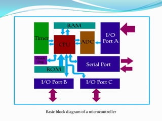
A microcontroller is a computer system on a single chip that contains a processor core, memory, and programmable input/output peripherals. Microcontrollers are commonly used to control objects, processes, or events. They are often embedded in devices to control their functions. A microcontroller contains a CPU, RAM, ROM, flash memory, I/O ports, an ADC, and timers. Common microcontrollers include the Intel 8051, Atmel ATmega 16, and PIC microcontrollers. The microcontroller reads programmed instructions from flash memory and executes them via the CPU to control its I/O pins based on inputs.


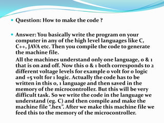


![Port Drive Register, PORTnIf the pin is configured as output (DDRn [x] = 1) PORTn register drives the corresponding value on the output pinsDDRA = 0xFF;PORTA = 0xF0;Output logic high on 4 MSB pins and logic low on 4 LSB pins](https://image.slidesharecdn.com/microcontroller-091029224732-phpapp02/85/Microcontroller-25-320.jpg)
![Port Drive Register, PORTnFor pins configured as input (DDRn[x] = 0) microcontroller connects a internal pull up resistor if the corresponding bit of PORTn is set If the PORTn bit is cleared, pin is Tristated DDRA = 0x00; PORTA = 0xF0;](https://image.slidesharecdn.com/microcontroller-091029224732-phpapp02/85/Microcontroller-26-320.jpg)