Downloaded 849 times

![25 | P a g e
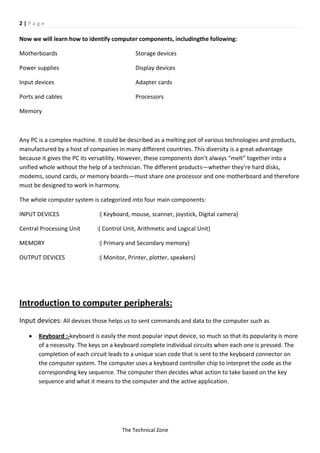
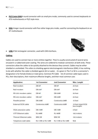
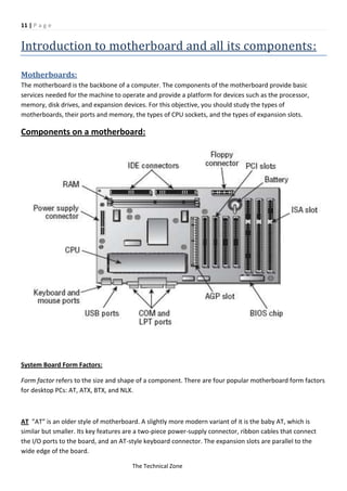
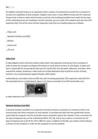
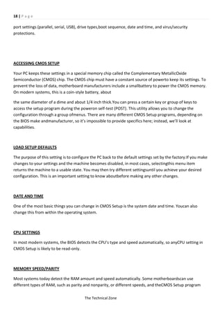
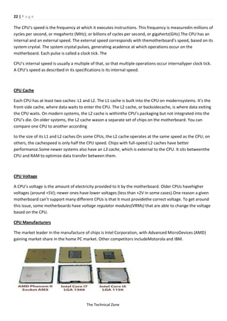
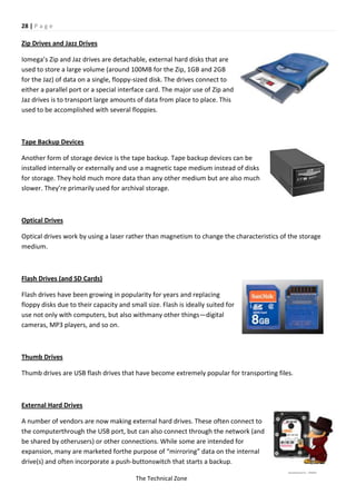
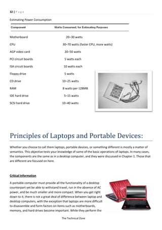
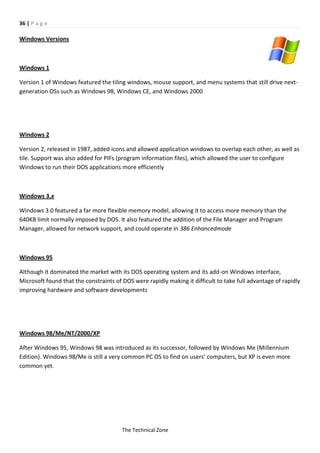
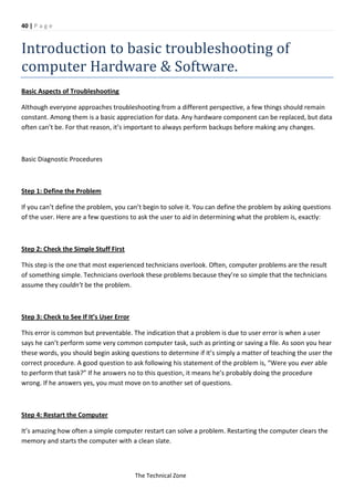
Various memory module form factors
RAMBUSA relatively new and extremely fast (up to 800MHz) technology that uses, for themost part, a new
methodology in memory system design. RAMBUS (also known as directRambus) is a memory bus that
transfers data at 800MHz. RAMBUS memory models (oftencalled Rambus inline memory modules
[RIMMs]), like DDR SDRAM, can transfer data onboth the rising and falling edges of a clock cycle. That
feature, combined with the 16-bit busfor efficient transfer of data, results in the ultra-high memory
transfer rate (800MHz) and thehigh bandwidth of up to 1.6GBps.
Memory Chip Package Types
Memory chips come in many different types of packages. The ones most frequently encounteredare
discussed in the following sections.
DUAL INLINE PACKAGE (DIP)
Dual inline package (DIP) memory is so named because the individual RAM chips use the DIPstylepackage
for the memory module. Older computers, such as the IBM AT, arranged thesesmall chips like rows of
caskets in a small memory “graveyard.” This type of memory has longbeen obsolete.
SIMMS
Single inline memory modules (SIMMs) were developed because DIPs took up too much realestate on the
logic board. Someone got the idea to put several DIP chips on a small circuitboard and then make that
board easily removable.
The Technical Zone](https://image.slidesharecdn.com/computerharwarecompletenotes-130326055943-phpapp02/85/Computer-harware-complete-notes-25-320.jpg)
![26 | P a g e
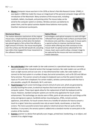
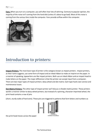
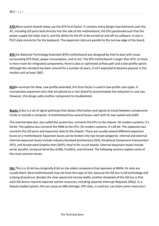
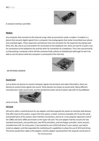
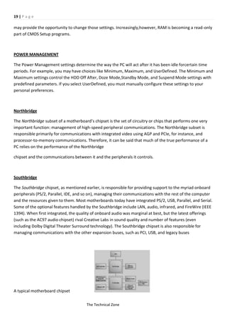
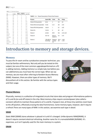
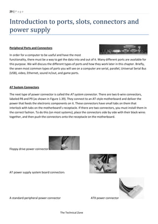
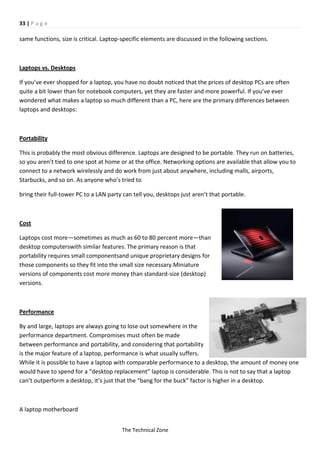
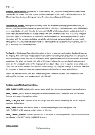
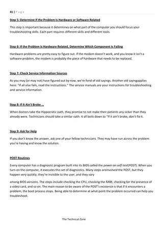
Each of these RAM circuit boards is a stick of RAM. There are two sizes of SIMMs: 30-pinand 72-pin. The
30-pin are older, 8-bit sticks. The 72-pin are 32-bit sticks. Figure 1.10 showsone of each. SIMMs are called
single because they’re single-sided. When you count the numberof pins (the metal tabs) along the bottom,
there are 30 or 72 of them. In contrast, DIMMs(dual inline memory modules) are double-sided; for
example, a 168-pin DIMM has 84 pins oneach side. DIMMS
AND RIMMSDIMMs are double-sided memory chips used in modern systems (Pentium and higher).
Theytypically have 168 pins and are 64 bits in width. Figure 1.11 shows a DIMM.A RIMM is just like a
DIMM, except it’s a Rambus DRAM stick, has 184 pins, and isslightly longer in size.
SODIMMS AND MICRODIMMS
Portable computers (notebooks and subnotebooks) require smaller sticks of RAM because of their smaller
size. Two types are small outline DIMM (SoDIMM) and MicroDIMM.
RAM Banks and Bit Width
As explained earlier, 30-pin SIMMs are 8-bit, 72-pin SIMMs are 32-bit, and DIMMs are 64-bit. The
motherboard has an address bus that carries data from the RAM to the CPU andchipset. It has a certain
width. On Pentium and higher systems, it’s 64-bit; on earlier systems,it’s 32-bit (386 and 486) or less (286
and below). A bank of RAM is a single stick or a groupof sticks where the collective bit width adds up to the
width of the address bus. For example, on a Pentium motherboard, a single bank consists of a single 64-bit
DIMMor a pair of two 32-bit SIMMs. For a 486 motherboard, a single bank is a single 32-bit SIMMor four 8-
bit SIMMs.
Video RAM
Video memory (also called video RAM [VRAM]) is used to store image data for processing bythe video
adapter. The more video memory an adapter has, the better the quality of image thatit can display. Also,
more VRAM allows the adapter to display a higher resolution of image.
The Technical Zone](https://image.slidesharecdn.com/computerharwarecompletenotes-130326055943-phpapp02/85/Computer-harware-complete-notes-26-320.jpg)

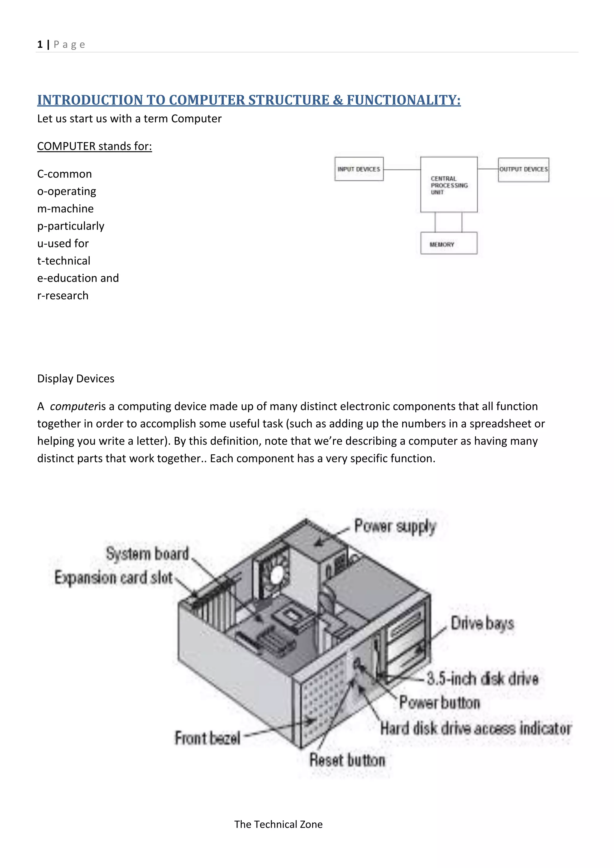
The document provides an overview of computer structure and functionality, detailing essential components such as motherboards, processors, memory, and input/output devices. It outlines the roles and technologies behind various peripherals, including keyboards, mice, and printers, alongside types of cables and connectors that facilitate communication among components. Furthermore, it categorizes computers into input, processing, storage, and output systems, emphasizing the importance of their harmonious operation for effective computing.