Download to read offline
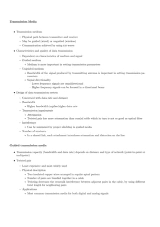
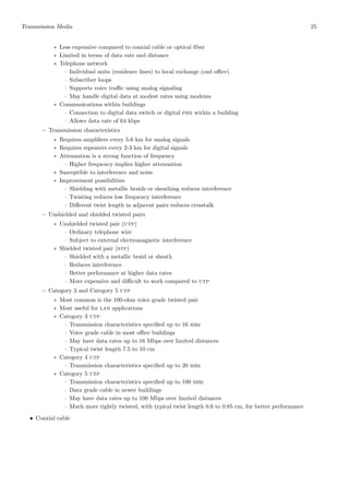


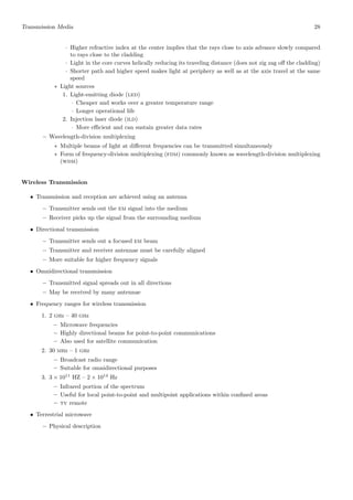
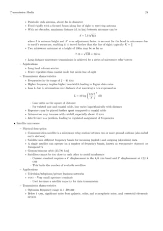


The document discusses different types of transmission media used for communication, including guided (wired) media like twisted pair, coaxial cable, and optical fiber, as well as unguided (wireless) transmission. It provides details on the characteristics of each medium, such as their bandwidth capabilities, applications, advantages and limitations. Overall, the document compares various physical transmission paths and how they enable data transmission over different distances and environments.


![Chapter-2 Communiction media [Autosaved].ppt](https://cdn.slidesharecdn.com/ss_thumbnails/chapter-2communictionmediaautosaved-260117143116-9787c933-thumbnail.jpg?width=640&height=640&fit=bounds)