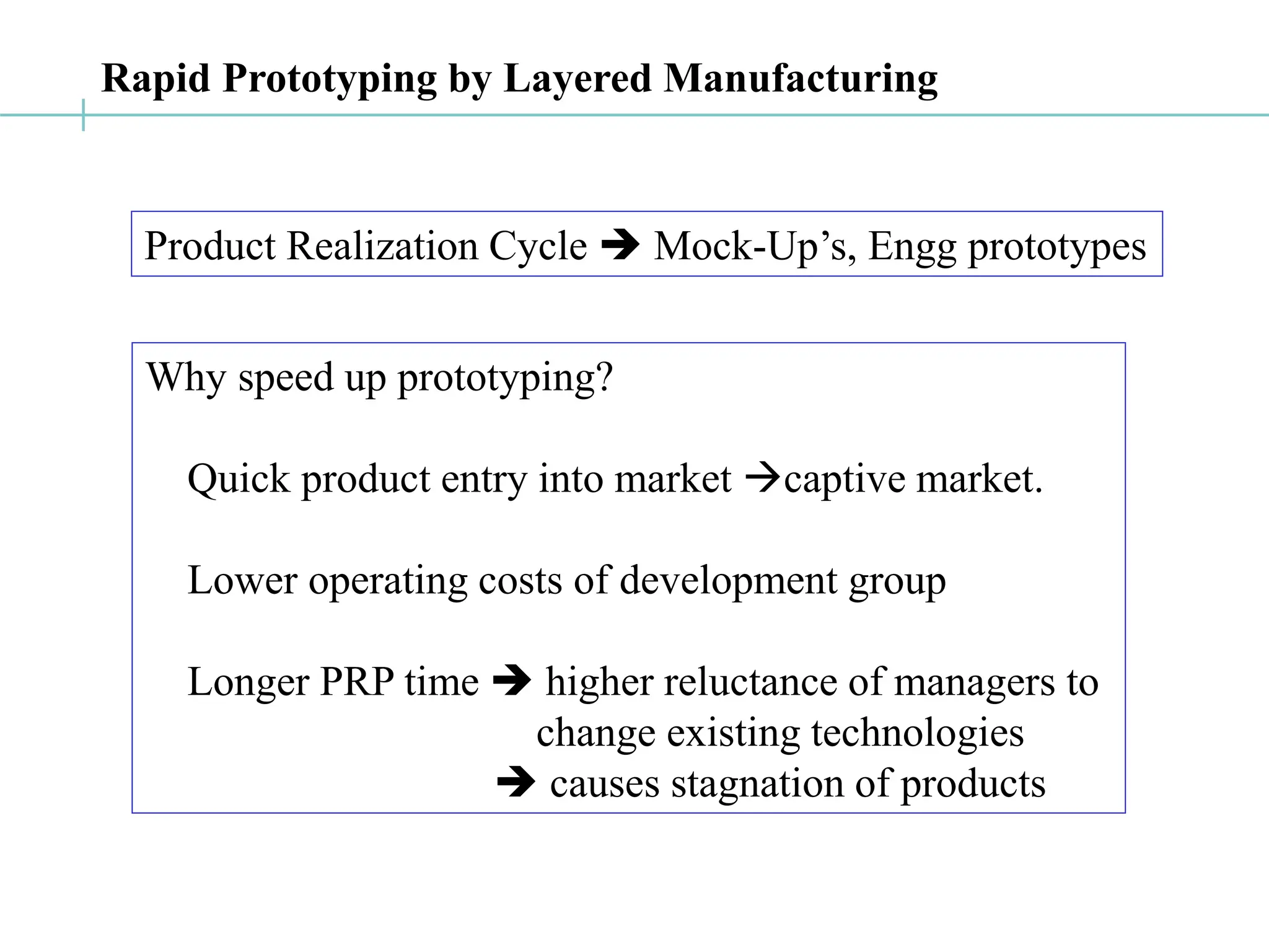
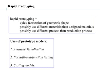
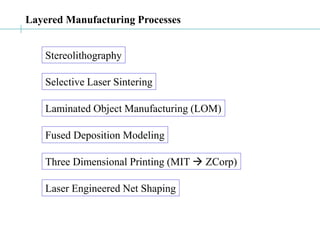
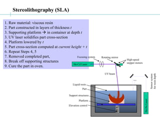
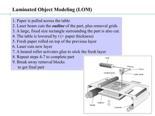
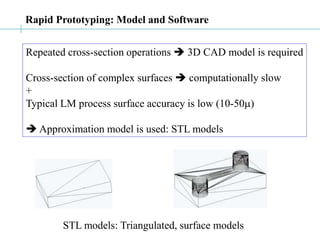
This document discusses rapid prototyping techniques such as stereolithography, selective laser sintering, fused deposition modeling, laminated object manufacturing, and 3D printing. It provides details on the processes, companies that develop the technologies, and applications. Rapid prototyping allows for quick fabrication of geometric shapes to create prototypes for testing form, fit, and function without using the final production materials or processes. STL files are commonly used as the standard file format for rapid prototyping systems.

![SLS: companies and applications
First commercialized by Prof Carl Deckard (UT Austin)
Marketed by DTM Corp.
DTM acquired by 3Dsystems Inc.
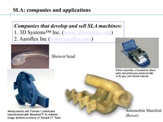
1. 3D Systems™ Inc. (www.3Dsystems.com)
2. EOS GmbH, Munich, Germany.
[both examples, source: DTM inc.]
Plastic parts using SLS Metal mold using SLS, injection molded parts](https://image.slidesharecdn.com/rp-231020002919-cc312fe3/85/RP-ppt-7-320.jpg)
![LOM: companies, applications
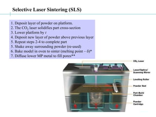
Original technology developed by Helisys Inc.;
Helisys acquired by Corum.
1. Cubic Technologies Inc [www.cubictechnologies.com]
2. KIRA Corp, Japan [www.kiracorp.co.jp]
[source: Corum Inc] [source: KIRA corporation]](https://image.slidesharecdn.com/rp-231020002919-cc312fe3/85/RP-ppt-11-320.jpg)
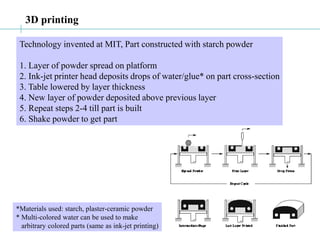
![3D Printing: companies, applications
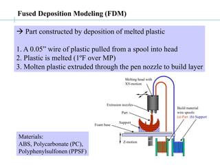
1. Z-corporation [www.zcorp.com]
2. Soligen [www.soligen.com]
Engine manifold for GM racing car
Cast after Direct Shell Production Casting
[source: www.soligen.com]](https://image.slidesharecdn.com/rp-231020002919-cc312fe3/85/RP-ppt-13-320.jpg)
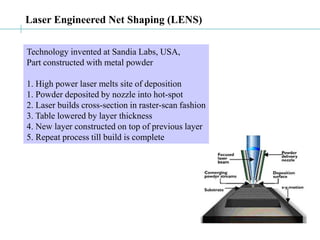
![LENS: companies, applications
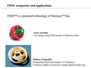
1. Optomec Inc, USA [www.optomec.com]
[source: www.optomec.com]](https://image.slidesharecdn.com/rp-231020002919-cc312fe3/85/RP-ppt-15-320.jpg)
![Rapid Prototyping by Layered Manufacturing
a
c
b
valid:
a b c
b c a, etc.
invalid:
b a c, etc.
outward
normal
a
c
b
valid:
a b c
b c a, etc.
invalid:
b a c, etc.
a
c
b
valid:
a b c
b c a, etc.
invalid:
b a c, etc.
outward
normal
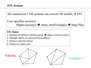
The ASCII STL File Format
Solid [name]
[facet normal [nx] [ny] [nz]
outer loop
vertex [v1x] [v1y] [v1z]
vertex [v2x] [v2y] [v2z]
vertex [v3x] [v3y] [v3z]
endloop
endfacet]+
endsolid [name]](https://image.slidesharecdn.com/rp-231020002919-cc312fe3/85/RP-ppt-18-320.jpg)


![[Deck] What's New in Spark-Iceberg Integration via DSV2.pptx](https://cdn.slidesharecdn.com/ss_thumbnails/deckwhatsnewinspark-icebergintegrationviadsv2-260210005337-25955b12-thumbnail.jpg?width=640&height=640&fit=bounds)
