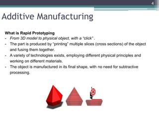
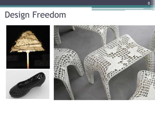
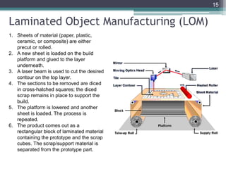
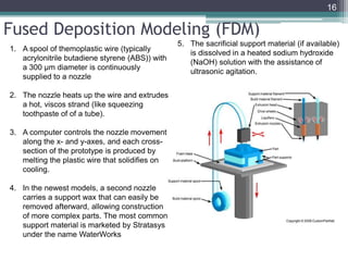
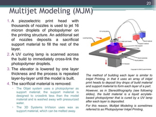
Additive Manufacturing
Introduction
• Manufacturing
▫ Subtractive manufacturing
▫ Additive manufacturing
• Subtractive Manufacturing
▫ Conventional Manufacturing
▫ Non-Conventional Manufacturing
2
Subtractive Vs Additive
EBF3 = Electron Beam Freeform Fabrication (Developed by NASA LaRC)
3
Additive Manufacturing
What is Rapid Prototyping
- From 3D model to physical object, with a “click” .
- The part is produced by “printing” multiple slices (cross sections) of the object
and fusing them together.
- A variety of technologies exists, employing different physical principles and
working on different materials.
- The object is manufactured in its final shape, with no need for subtractive
processing.
4
Why is Additive Manufacturing the Next Frontier?
5
Challenge
• Range of abilities and no
one size fits all chair
Task
• Personalized solution to
maximize performance
Customization
6
3D Printed
Seat
The Customized Outcome
7
Design Freedom
8
Low Volume Manufacturing
9
Design for AM – Case: bottle opener
10
Design for AM – Case: Buckle
68 grams
11
AM Process Flow
• CAD model
• STL file Conversion
• Part Orientation
• Support Generation
• Model Slicing
• Tool Path Generation
• Printing
• Post Processing (if applicable)
12
AM techniques
• Stereolithography (SLA)
• Fused Deposition Modeling (FDM)
• Selective Laser Sintering (SLS)
• Laminated Object Manufacturing (LOM)
• Laser Engineered Net Shaping (LENS)
• Multi Jet Modeling (MJM)
• Electron Beam Melting (EDM) & etc
13
Stereolithography (SLA)
1. A structure support base is positioned
on an elevator structure and immersed
in a tank of liquid photosensitive
monomer, with only a thin liquid film
above it
2. A UV laser locally cross-links the
monomer on the thin liquid film above
the structure support base
3. The elevator plate is lowered by a small
prescribed step, exposing a fresh layer
of liquid monomer, and the process is
repeated
4. At the end of the job, the whole part is
cured once more after excess resin and
support structures are removed
14
Laminated Object Manufacturing (LOM)
1. Sheets of material (paper, plastic,
ceramic, or composite) are either
precut or rolled.
2. A new sheet is loaded on the build
platform and glued to the layer
underneath.
3. A laser beam is used to cut the desired
contour on the top layer.
4. The sections to be removed are diced
in cross-hatched squares; the diced
scrap remains in place to support the
build.
5. The platform is lowered and another
sheet is loaded. The process is
repeated.
6. The product comes out as a
rectangular block of laminated material
containing the prototype and the scrap
cubes. The scrap/support material is
separated from the prototype part.
15
Fused Deposition Modeling (FDM)
1. A spool of themoplastic wire (typically
acrylonitrile butadiene styrene (ABS)) with
a 300 μm diameter is continuously
supplied to a nozzle
2. The nozzle heats up the wire and extrudes
a hot, viscos strand (like squeezing
toothpaste of of a tube).
3. A computer controls the nozzle movement
along the x- and y-axes, and each cross-
section of the prototype is produced by
melting the plastic wire that solidifies on
cooling.
4. In the newest models, a second nozzle
carries a support wax that can easily be
removed afterward, allowing construction
of more complex parts. The most common
support material is marketed by Stratasys
under the name WaterWorks
5. The sacrificial support material (if available)
is dissolved in a heated sodium hydroxide
(NaOH) solution with the assistance of
ultrasonic agitation.
16
Selective Laser Sintering (SLS)
1. A continuous layer of powder is
deposited on the fabrication
platform
2. A focused laser beam is used to
fuse/sinter powder particles in a
small volume within the layer
3. The laser beam is scanned to
define a 2D slice of the object
within the layer
4. The fabrication piston is
lowered, the powder delivery
piston is raised and a new layer
is deposited
5. After removal from the machine,
the unsintered dry powder is
brushed off and recycled
17
•Inert shielding gas jet deposits
powder that is molten to the part
with laser
•Platform moves, while nozzle is
usually stationary
•Materials:
•Metal
•Uses: Repairs
Directed Energy Deposition (DED)
Laser Engineered Net Shaping (LENS)
18
Electron Beam Melting (EBM)
1. The fabrication chamber is
maintained at high vacuum and high
temperature
2. A layer of metal powder is deposited
on the fabrication platform
3. A focused electron beam is used to
melt the powder particles in a small
volume within the layer
4. The electron beam is scanned to
define a 2D slice of the object within
the layer
5. The build table is lowered, and a
new layer of dry powder is deposited
on top of the previous layer
6. After removal from the machine, the
unmelted powder is brushed off and
recycled
19
Multijet Modeling (MJM)
1. A piezoelectric print head with
thousands of nozzles is used to jet 16
micron droplets of photopolymer on
the printing structure. An additional set
of nozzles deposits a sacrificial
support material to fill the rest of the
layer.
2. A UV curing lamp is scanned across
the build to immediately cross-link the
photopolymer droplets.
3. The elevator is lowered by one layer
thickness and the process is repeated
layer-by-layer until the model is built.
4. The sacrificial material is removed:
▫ The Objet system uses a photopolymer as
support material; the support material is
designed to crosslink less than the model
material and is washed away with pressurized
water.
▫ The 3D Systems InVision uses wax as
support material, which can be melted away.
The method of building each layer is similar to
Inkjet Printing, in that it uses an array of inkjet
print heads to deposit tiny drops of build material
and support material to form each layer of a part.
However, as in Stereolithography (see following
slides), the build material is a liquid acrylate-
based photopolymer that is cured by a UV lamp
after each layer is deposited.
For this reason, Multijet Modeling is sometimes
referred to as Photopolymer Inkjet Printing.
20
APPLICATIONS AND OF AM
21
Medical Applications
Hip socket, Ala Ortho, Italy, made on
Arcam machine
Laser Sintered Hearing Aids,
EOS/Materialise
22
Beauty and the beak
23
Food Printers
MIT Media Lab
24
FabCafe in the Shibuya, Tokyo offers
custom-printed chocolate, that resemble
a customer’s face. It’s done with 3D
printing technology
“Eat Your Face Machine” (EYFM) is a 3D printer
developed by David Carr and the MIT Media Lab
25
Thank you
26

Additive Manufacturing PPT.pptx

  • 1.
  • 2.
    Introduction • Manufacturing ▫ Subtractivemanufacturing ▫ Additive manufacturing • Subtractive Manufacturing ▫ Conventional Manufacturing ▫ Non-Conventional Manufacturing 2
  • 3.
    Subtractive Vs Additive EBF3= Electron Beam Freeform Fabrication (Developed by NASA LaRC) 3
  • 4.
    Additive Manufacturing What isRapid Prototyping - From 3D model to physical object, with a “click” . - The part is produced by “printing” multiple slices (cross sections) of the object and fusing them together. - A variety of technologies exists, employing different physical principles and working on different materials. - The object is manufactured in its final shape, with no need for subtractive processing. 4
  • 5.
    Why is AdditiveManufacturing the Next Frontier? 5
  • 6.
    Challenge • Range ofabilities and no one size fits all chair Task • Personalized solution to maximize performance Customization 6
  • 7.
  • 8.
  • 9.
  • 10.
    Design for AM– Case: bottle opener 10
  • 11.
    Design for AM– Case: Buckle 68 grams 11
  • 12.
    AM Process Flow •CAD model • STL file Conversion • Part Orientation • Support Generation • Model Slicing • Tool Path Generation • Printing • Post Processing (if applicable) 12
  • 13.
    AM techniques • Stereolithography(SLA) • Fused Deposition Modeling (FDM) • Selective Laser Sintering (SLS) • Laminated Object Manufacturing (LOM) • Laser Engineered Net Shaping (LENS) • Multi Jet Modeling (MJM) • Electron Beam Melting (EDM) & etc 13
  • 14.
    Stereolithography (SLA) 1. Astructure support base is positioned on an elevator structure and immersed in a tank of liquid photosensitive monomer, with only a thin liquid film above it 2. A UV laser locally cross-links the monomer on the thin liquid film above the structure support base 3. The elevator plate is lowered by a small prescribed step, exposing a fresh layer of liquid monomer, and the process is repeated 4. At the end of the job, the whole part is cured once more after excess resin and support structures are removed 14
  • 15.
    Laminated Object Manufacturing(LOM) 1. Sheets of material (paper, plastic, ceramic, or composite) are either precut or rolled. 2. A new sheet is loaded on the build platform and glued to the layer underneath. 3. A laser beam is used to cut the desired contour on the top layer. 4. The sections to be removed are diced in cross-hatched squares; the diced scrap remains in place to support the build. 5. The platform is lowered and another sheet is loaded. The process is repeated. 6. The product comes out as a rectangular block of laminated material containing the prototype and the scrap cubes. The scrap/support material is separated from the prototype part. 15
  • 16.
    Fused Deposition Modeling(FDM) 1. A spool of themoplastic wire (typically acrylonitrile butadiene styrene (ABS)) with a 300 μm diameter is continuously supplied to a nozzle 2. The nozzle heats up the wire and extrudes a hot, viscos strand (like squeezing toothpaste of of a tube). 3. A computer controls the nozzle movement along the x- and y-axes, and each cross- section of the prototype is produced by melting the plastic wire that solidifies on cooling. 4. In the newest models, a second nozzle carries a support wax that can easily be removed afterward, allowing construction of more complex parts. The most common support material is marketed by Stratasys under the name WaterWorks 5. The sacrificial support material (if available) is dissolved in a heated sodium hydroxide (NaOH) solution with the assistance of ultrasonic agitation. 16
  • 17.
    Selective Laser Sintering(SLS) 1. A continuous layer of powder is deposited on the fabrication platform 2. A focused laser beam is used to fuse/sinter powder particles in a small volume within the layer 3. The laser beam is scanned to define a 2D slice of the object within the layer 4. The fabrication piston is lowered, the powder delivery piston is raised and a new layer is deposited 5. After removal from the machine, the unsintered dry powder is brushed off and recycled 17
  • 18.
    •Inert shielding gasjet deposits powder that is molten to the part with laser •Platform moves, while nozzle is usually stationary •Materials: •Metal •Uses: Repairs Directed Energy Deposition (DED) Laser Engineered Net Shaping (LENS) 18
  • 19.
    Electron Beam Melting(EBM) 1. The fabrication chamber is maintained at high vacuum and high temperature 2. A layer of metal powder is deposited on the fabrication platform 3. A focused electron beam is used to melt the powder particles in a small volume within the layer 4. The electron beam is scanned to define a 2D slice of the object within the layer 5. The build table is lowered, and a new layer of dry powder is deposited on top of the previous layer 6. After removal from the machine, the unmelted powder is brushed off and recycled 19
  • 20.
    Multijet Modeling (MJM) 1.A piezoelectric print head with thousands of nozzles is used to jet 16 micron droplets of photopolymer on the printing structure. An additional set of nozzles deposits a sacrificial support material to fill the rest of the layer. 2. A UV curing lamp is scanned across the build to immediately cross-link the photopolymer droplets. 3. The elevator is lowered by one layer thickness and the process is repeated layer-by-layer until the model is built. 4. The sacrificial material is removed: ▫ The Objet system uses a photopolymer as support material; the support material is designed to crosslink less than the model material and is washed away with pressurized water. ▫ The 3D Systems InVision uses wax as support material, which can be melted away. The method of building each layer is similar to Inkjet Printing, in that it uses an array of inkjet print heads to deposit tiny drops of build material and support material to form each layer of a part. However, as in Stereolithography (see following slides), the build material is a liquid acrylate- based photopolymer that is cured by a UV lamp after each layer is deposited. For this reason, Multijet Modeling is sometimes referred to as Photopolymer Inkjet Printing. 20
  • 21.
  • 22.
    Medical Applications Hip socket,Ala Ortho, Italy, made on Arcam machine Laser Sintered Hearing Aids, EOS/Materialise 22
  • 23.
  • 24.
  • 25.
    FabCafe in theShibuya, Tokyo offers custom-printed chocolate, that resemble a customer’s face. It’s done with 3D printing technology “Eat Your Face Machine” (EYFM) is a 3D printer developed by David Carr and the MIT Media Lab 25
  • 26.