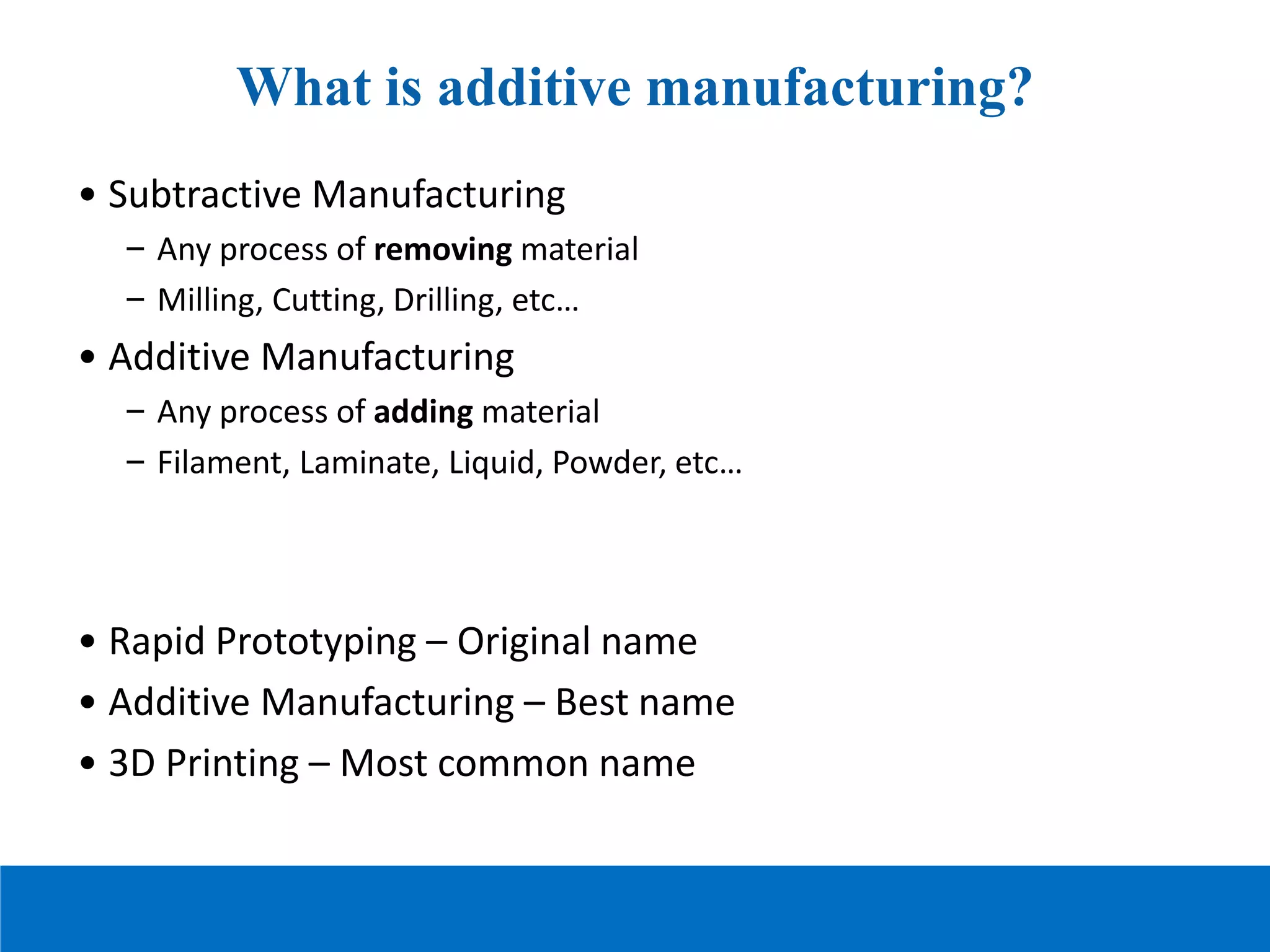
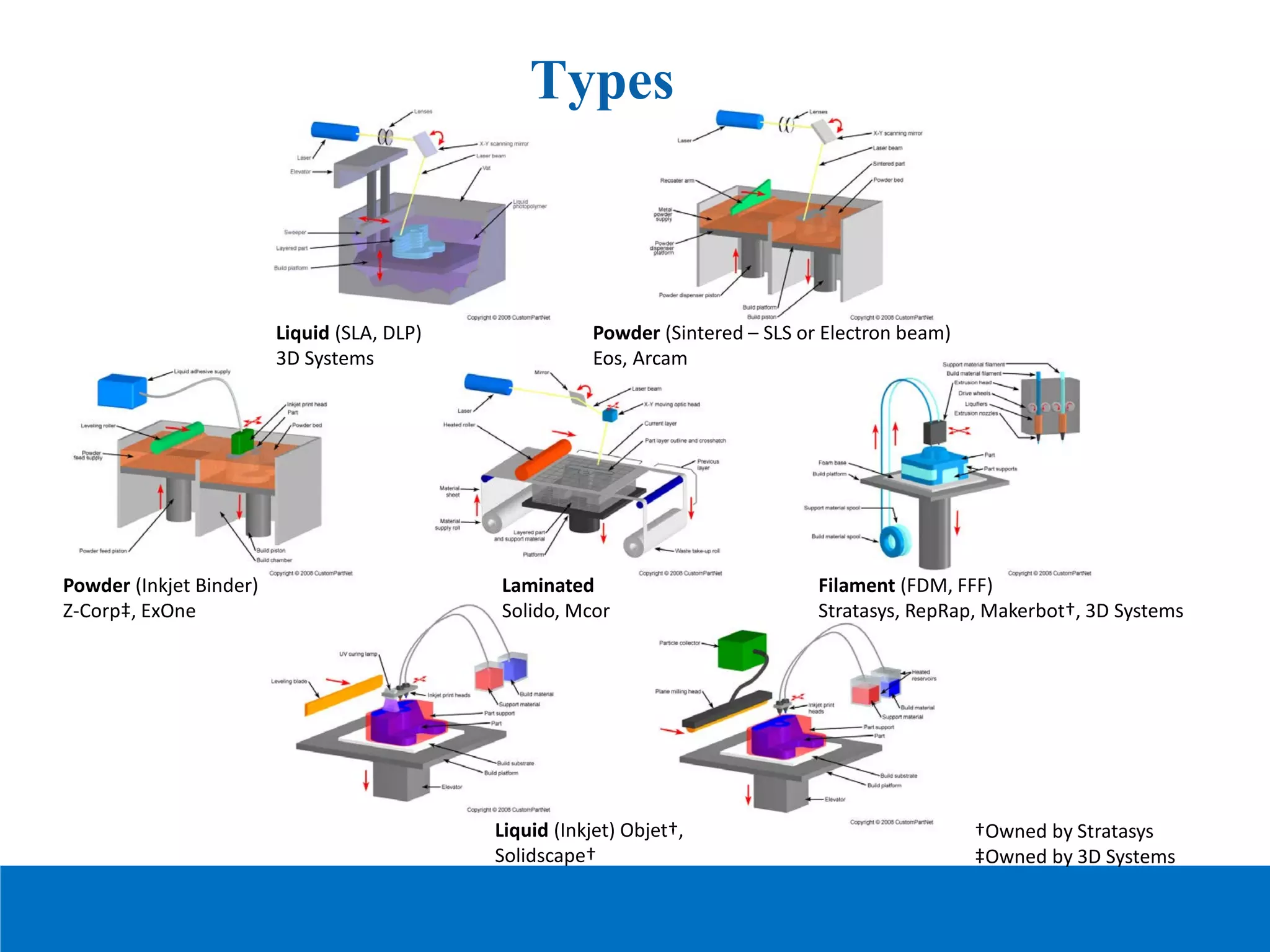
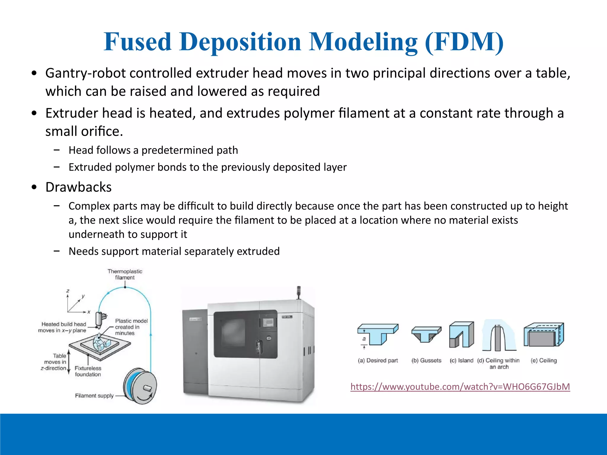
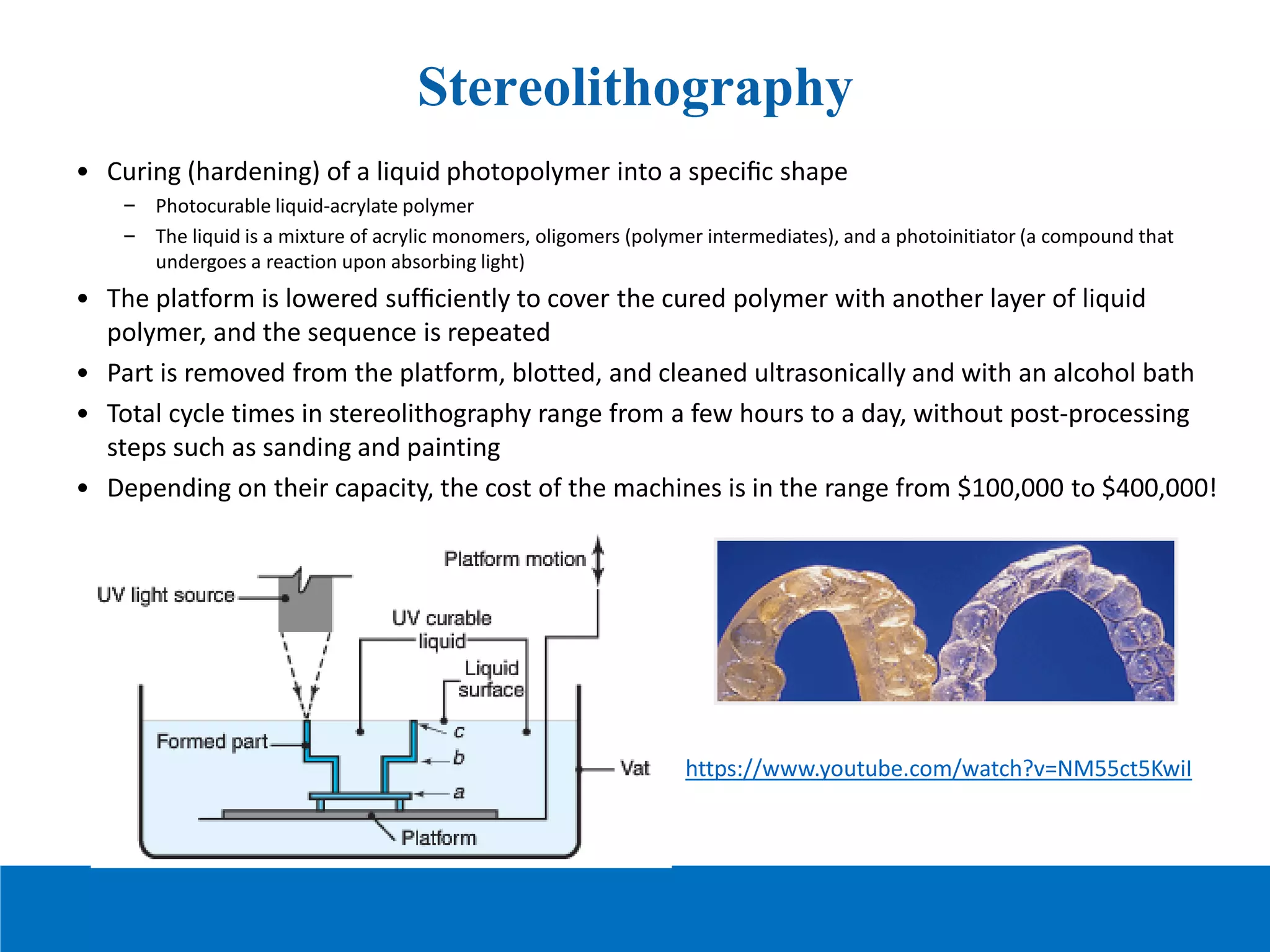
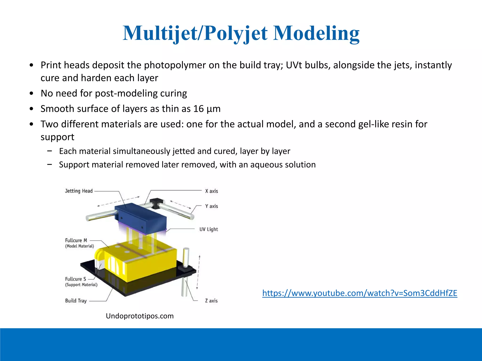
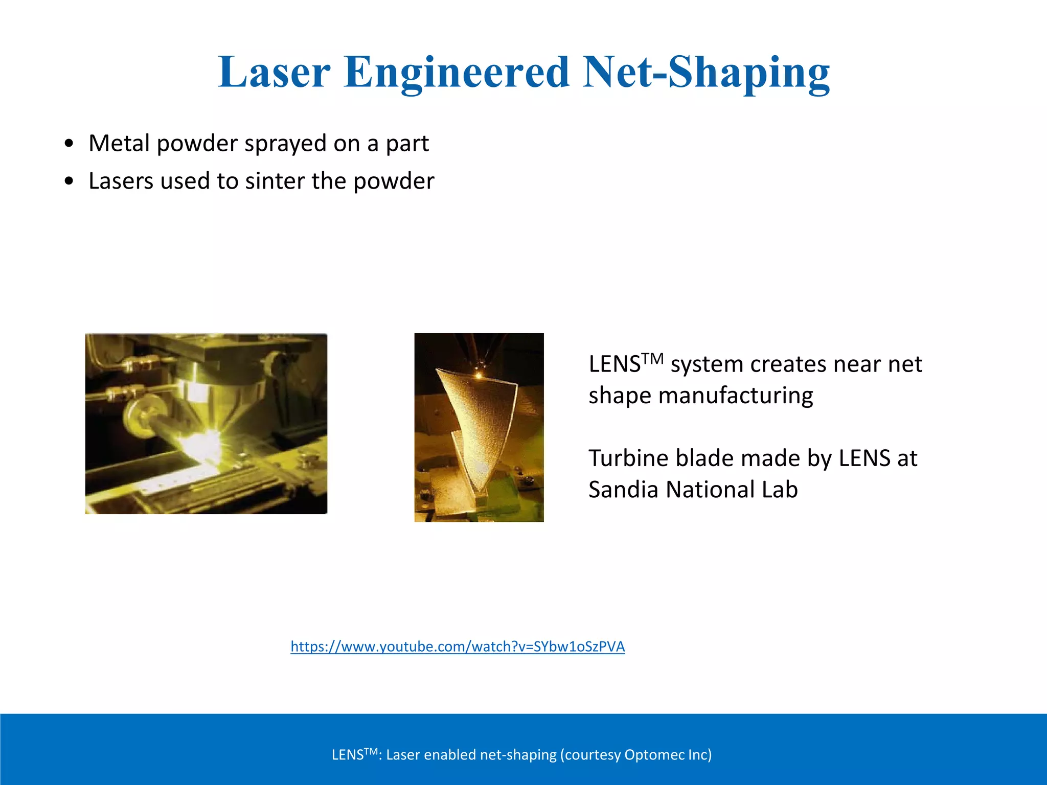
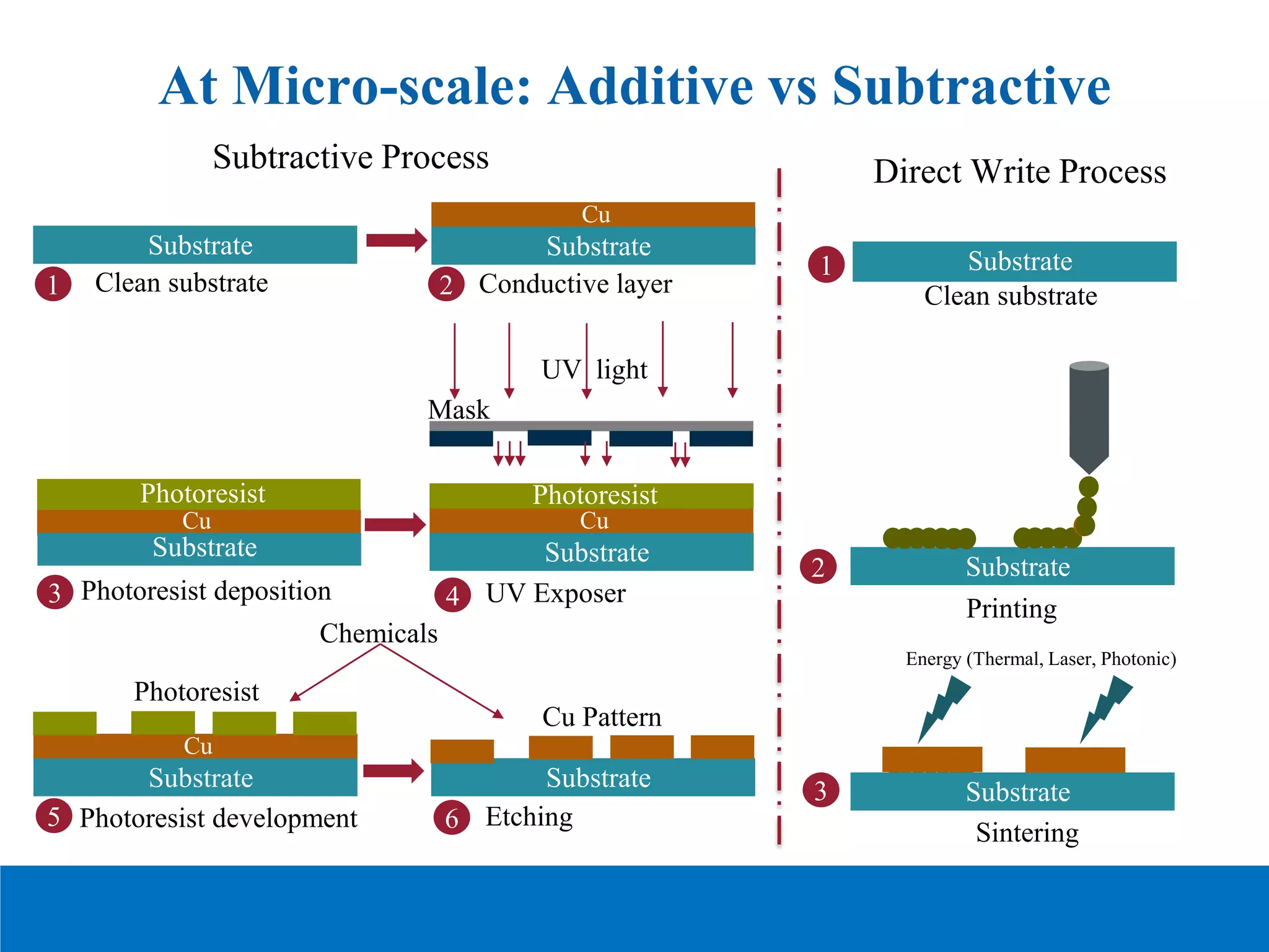
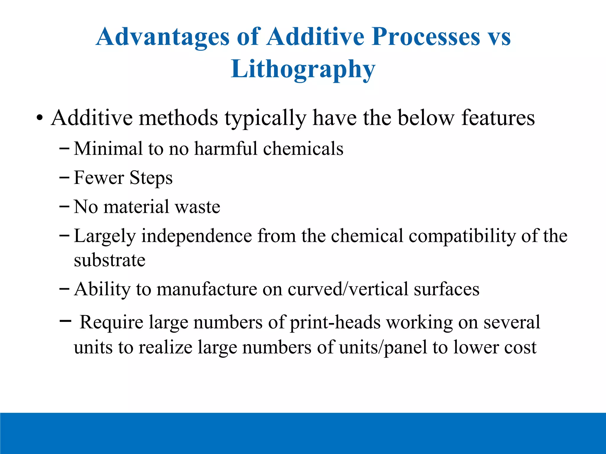
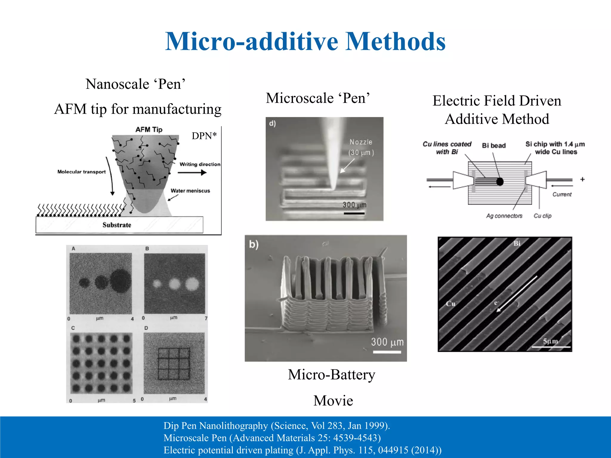
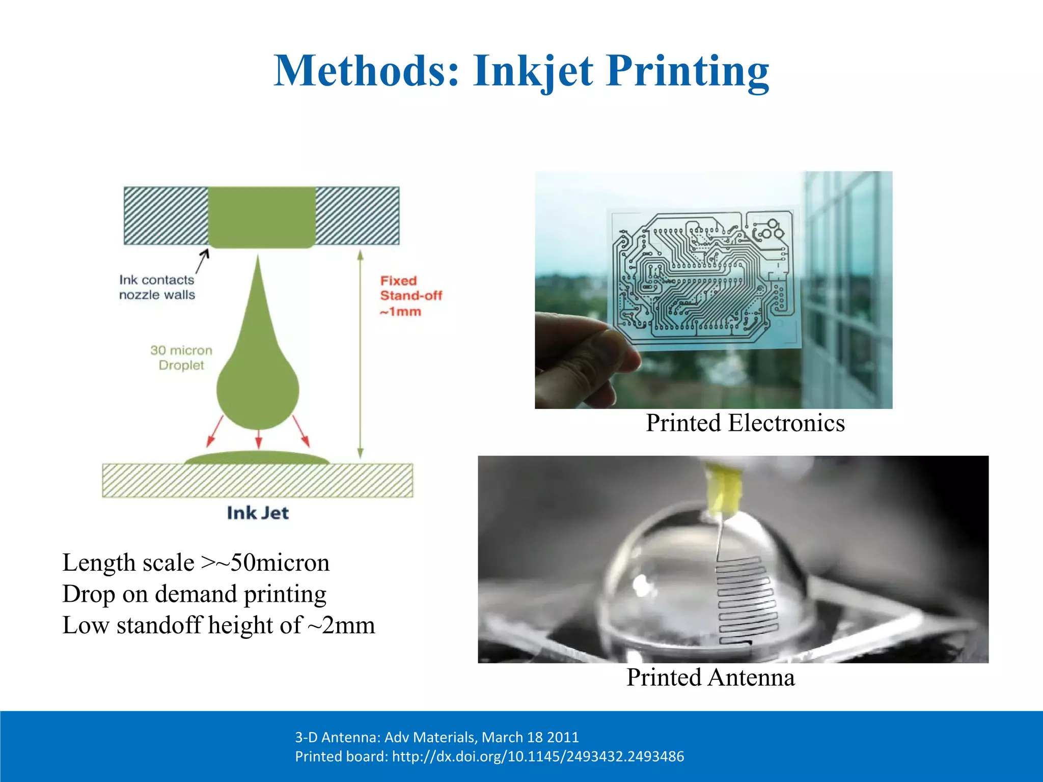
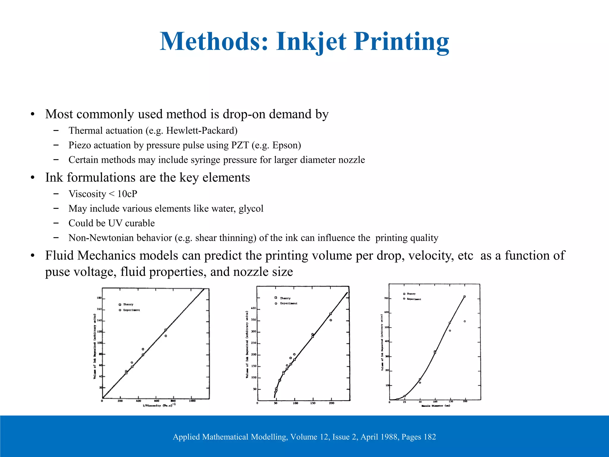
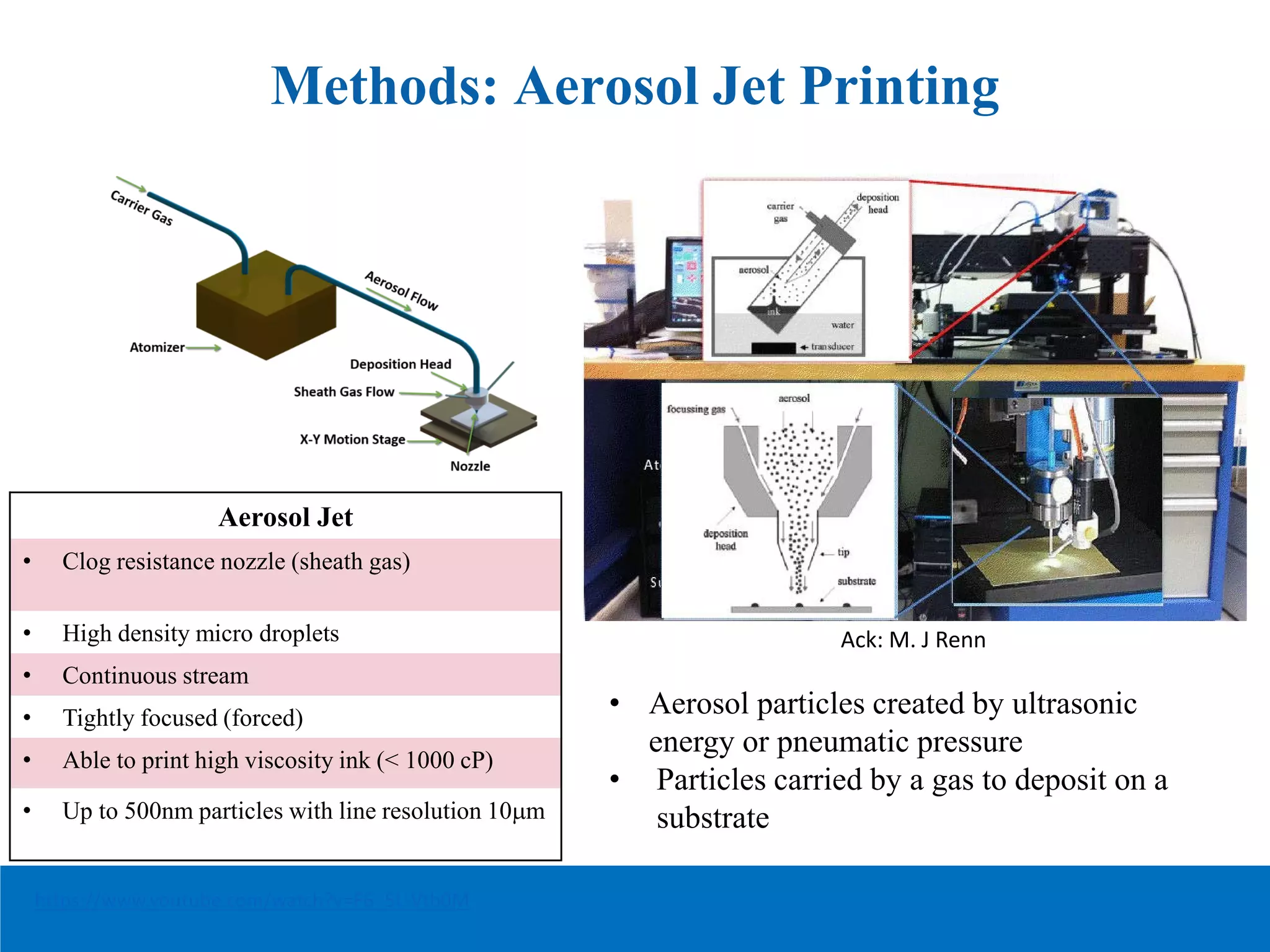
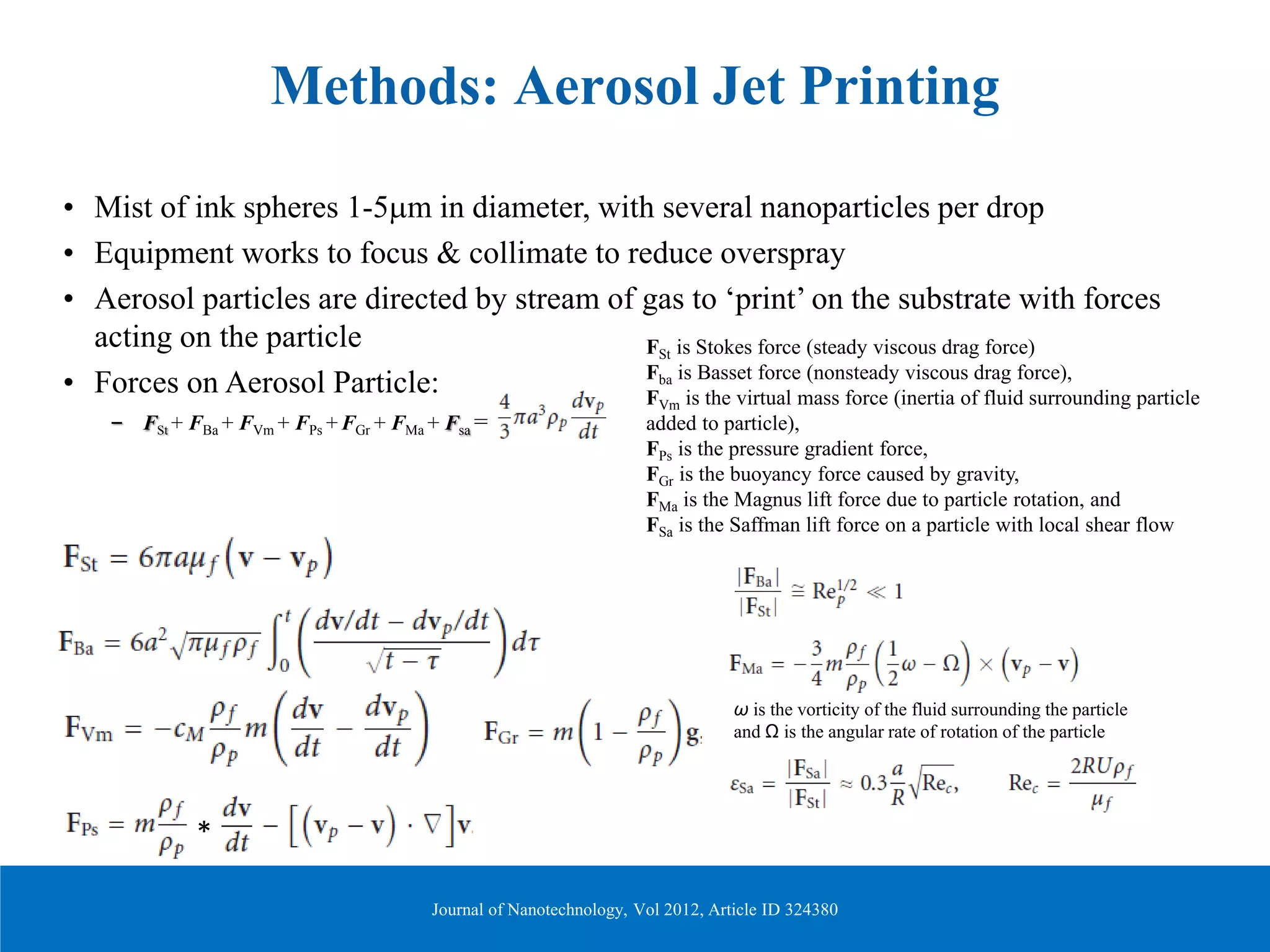
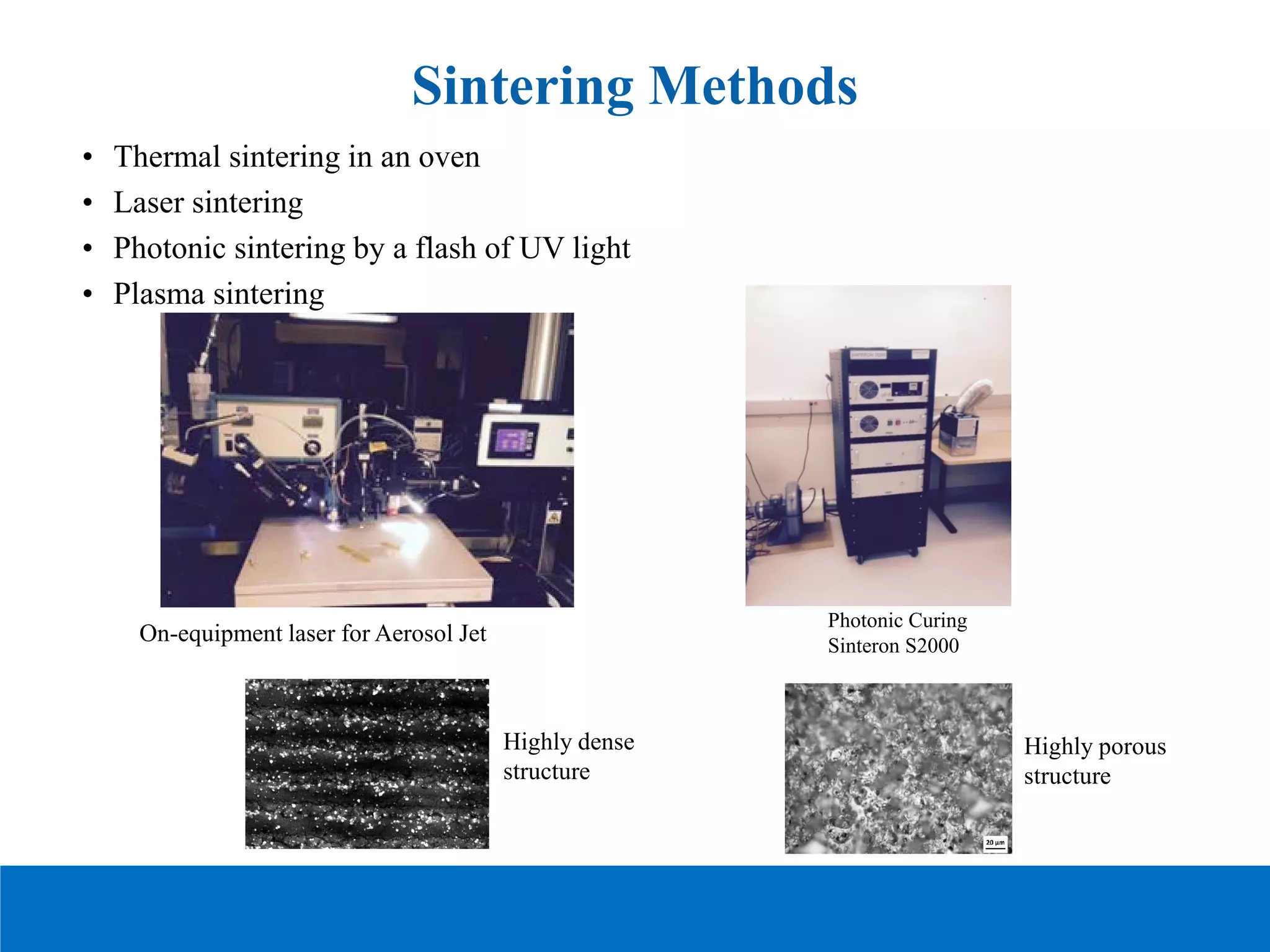
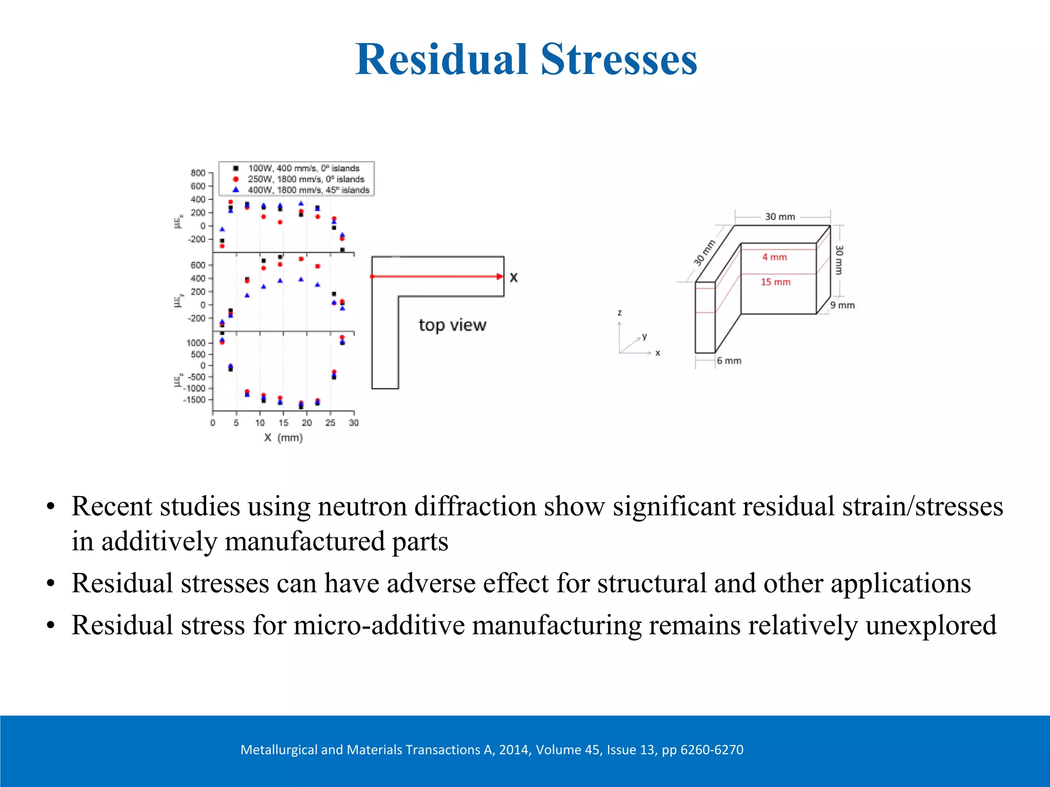
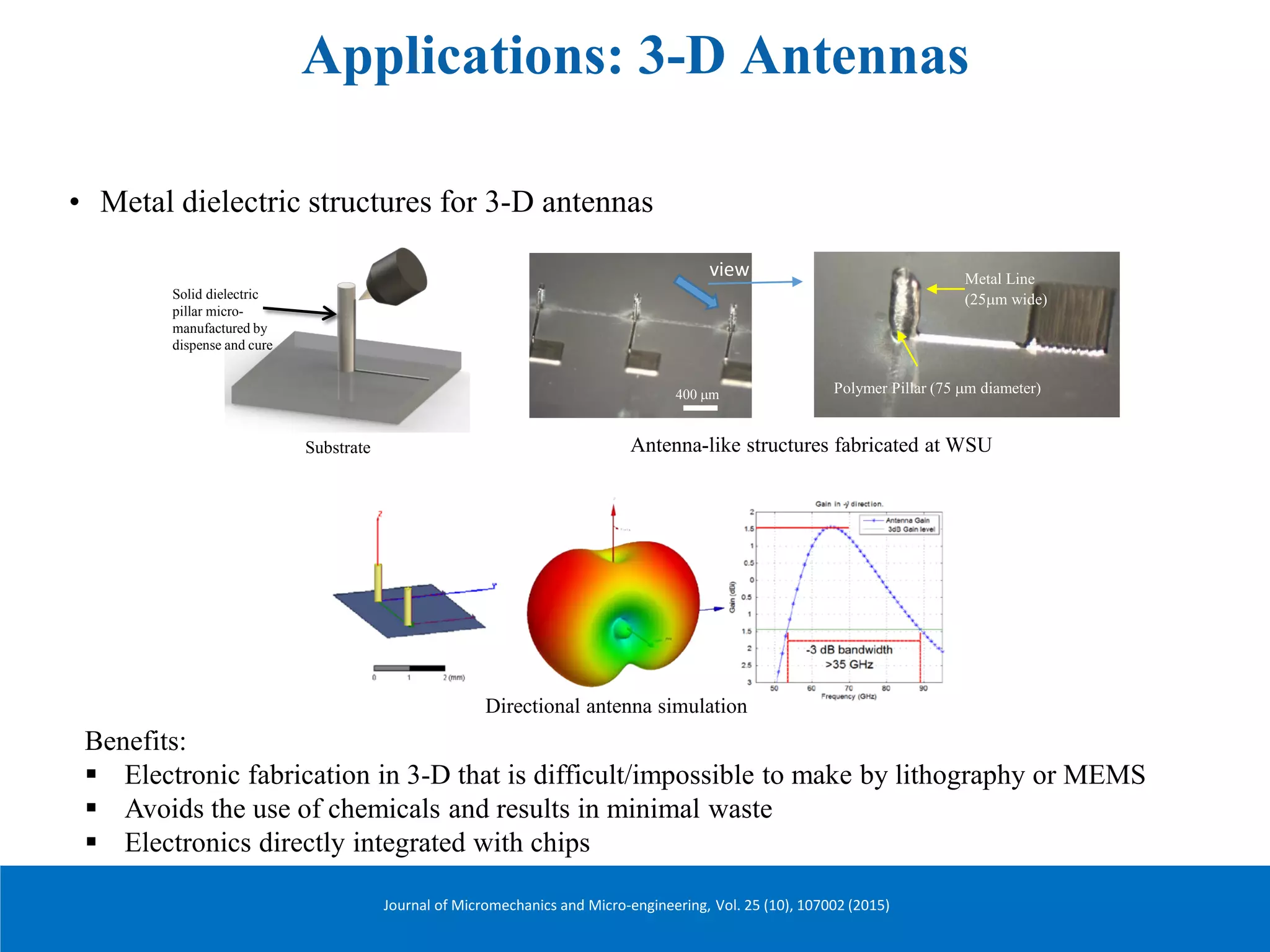
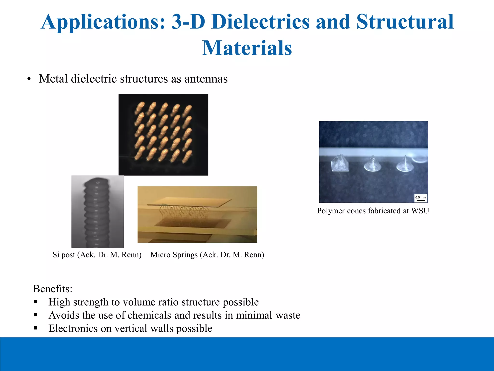
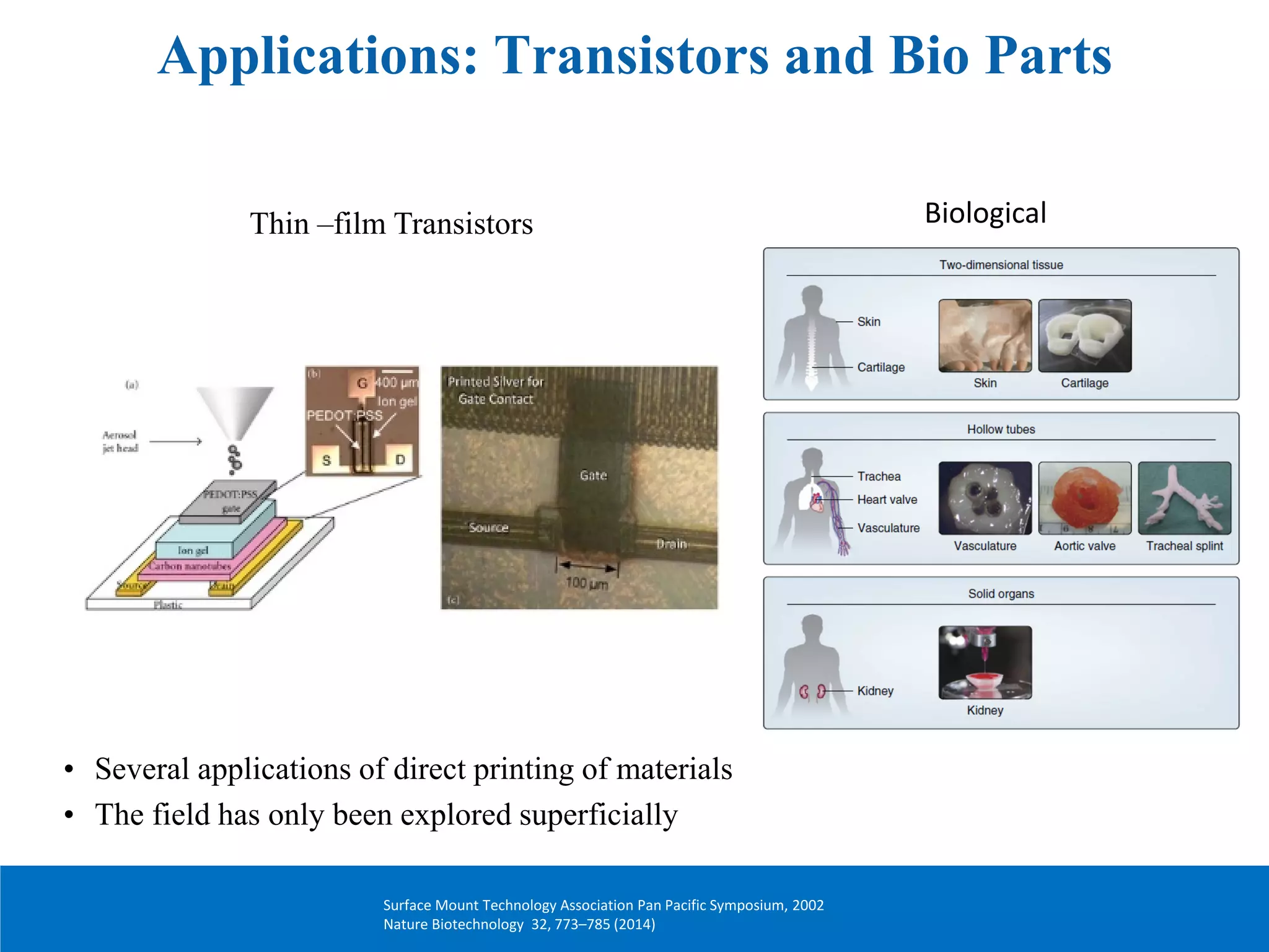
Additive manufacturing, also known as 3D printing, involves building 3D objects by adding material layer by layer based on a digital model. The document discusses several additive manufacturing techniques including fused deposition modeling (FDM), stereolithography, multijet/polyjet modeling, selective laser sintering, and aerosol jet printing. It also covers applications of additive manufacturing at the microscale such as printing 3D antennas, transistors, and biological structures. While additive manufacturing offers advantages over traditional manufacturing methods, the document notes challenges in areas like reliability need to be addressed as these techniques are applied to newer applications.
BAHIR DAR UNIVERSITYBAHIR DAR INSTITUTE OF TECHNOLOGY (BiT)FACULTY OF MECHANICAL AND INDUSTRIAL ENGINEERING Rapid Prototyping & Reverse Engineering [MEng6123]
Rapid Prototyping Techniques
They can be categorized by material: photopolymer, thermoplastic, and adhesives.
Photopolymer systems start with a liquid resin, which is then solidified by exposure to a specific wavelength of light.
Thermoplastic systems begin with a solid material, which is then melted and fuses upon cooling.
The adhesive systems use a binder to connect the primary construction material
Rapid Prototyping Techniques
The initial state of material can come in either
solid, liquid or powder state
The current range materials include
paper, polymer, nylon, wax, resins, metals and ceramics.
Liquid Based RP Systems
Solidification of a Liquid Polymer
These process involve the solidification of a resin via electromagnetic radiation
There are different processes in this category
Stereolithography (SL)
Liquid Thermal Polymerization (LTP)
Beam Interference Solidification (BIS)
Solid Ground Curing (SGC)
Objet Quadra Process (Objet)
Holographic Interference Solidification
Liquid Based RP Systems
Stereolithography (SL)
Principle of Operation
Patented in 1986,
Started the RP revolution
Developed by 3D Systems, Inc.
Most popular RP methods.
The technique builds 3D models from liquid photosensitive polymers that solidify when exposed to ultraviolet light.
Builds plastic parts a layer at a time by tracing a laser beam on the surface of a vat of liquid photopolymer.
The liquid photopolymer, quickly solidifies wherever the laser beam strikes the surface of the liquid
This presentation deals with the rapid prototyping fundamentals, rapid tooling vs conventional tooling and types of RP such as stereolithography,fused deposition modelling , laminated object manufacturing , 3d printing and selective laser sintering.
The presentation covers all the methods of Rapid protoyping and various aspects related to it.
The Topics covered in the presentation are
1) Droplet Deposition Manufacturing
2) Laminated Object Manufacturing
3) Fused Deposition Modeling
4) Selective Laser Manufacturing
5) Sterolithography
A brief knowledge about surface treatment, which is a process applied to the surface of a material to make it better in some way, for example by making it more resistant to corrosion or wear. Shot peening is a surface treatment in which small hard pellets are shot against the surface of a metal to make it more resistant to fatigue.
Non Traditional Machining is playing vital role in now a days in mechanical Industries so student it should be need sound knowledge in this particular subject due to impact of this subject i am prepare in this materials it is most useful for my students...
All The Best ...
By: Author-Prof.S.Sathishkumar
Saudi Arabia stands as a titan in the global energy landscape, renowned for its abundant oil and gas resources. It's the largest exporter of petroleum and holds some of the world's most significant reserves. Let's delve into the top 10 oil and gas projects shaping Saudi Arabia's energy future in 2024.
CFD Simulation of By-pass Flow in a HRSG module by R&R Consult.pptxR&R Consult
CFD analysis is incredibly effective at solving mysteries and improving the performance of complex systems!
Here's a great example: At a large natural gas-fired power plant, where they use waste heat to generate steam and energy, they were puzzled that their boiler wasn't producing as much steam as expected.
R&R and Tetra Engineering Group Inc. were asked to solve the issue with reduced steam production.
An inspection had shown that a significant amount of hot flue gas was bypassing the boiler tubes, where the heat was supposed to be transferred.
R&R Consult conducted a CFD analysis, which revealed that 6.3% of the flue gas was bypassing the boiler tubes without transferring heat. The analysis also showed that the flue gas was instead being directed along the sides of the boiler and between the modules that were supposed to capture the heat. This was the cause of the reduced performance.
Based on our results, Tetra Engineering installed covering plates to reduce the bypass flow. This improved the boiler's performance and increased electricity production.
It is always satisfying when we can help solve complex challenges like this. Do your systems also need a check-up or optimization? Give us a call!
Work done in cooperation with James Malloy and David Moelling from Tetra Engineering.
More examples of our work https://www.r-r-consult.dk/en/cases-en/
Hybrid optimization of pumped hydro system and solar- Engr. Abdul-Azeez.pdffxintegritypublishin
Advancements in technology unveil a myriad of electrical and electronic breakthroughs geared towards efficiently harnessing limited resources to meet human energy demands. The optimization of hybrid solar PV panels and pumped hydro energy supply systems plays a pivotal role in utilizing natural resources effectively. This initiative not only benefits humanity but also fosters environmental sustainability. The study investigated the design optimization of these hybrid systems, focusing on understanding solar radiation patterns, identifying geographical influences on solar radiation, formulating a mathematical model for system optimization, and determining the optimal configuration of PV panels and pumped hydro storage. Through a comparative analysis approach and eight weeks of data collection, the study addressed key research questions related to solar radiation patterns and optimal system design. The findings highlighted regions with heightened solar radiation levels, showcasing substantial potential for power generation and emphasizing the system's efficiency. Optimizing system design significantly boosted power generation, promoted renewable energy utilization, and enhanced energy storage capacity. The study underscored the benefits of optimizing hybrid solar PV panels and pumped hydro energy supply systems for sustainable energy usage. Optimizing the design of solar PV panels and pumped hydro energy supply systems as examined across diverse climatic conditions in a developing country, not only enhances power generation but also improves the integration of renewable energy sources and boosts energy storage capacities, particularly beneficial for less economically prosperous regions. Additionally, the study provides valuable insights for advancing energy research in economically viable areas. Recommendations included conducting site-specific assessments, utilizing advanced modeling tools, implementing regular maintenance protocols, and enhancing communication among system components.
About
Indigenized remote control interface card suitable for MAFI system CCR equipment. Compatible for IDM8000 CCR. Backplane mounted serial and TCP/Ethernet communication module for CCR remote access. IDM 8000 CCR remote control on serial and TCP protocol.
• Remote control: Parallel or serial interface.
• Compatible with MAFI CCR system.
• Compatible with IDM8000 CCR.
• Compatible with Backplane mount serial communication.
• Compatible with commercial and Defence aviation CCR system.
• Remote control system for accessing CCR and allied system over serial or TCP.
• Indigenized local Support/presence in India.
• Easy in configuration using DIP switches.
Technical Specifications
Indigenized remote control interface card suitable for MAFI system CCR equipment. Compatible for IDM8000 CCR. Backplane mounted serial and TCP/Ethernet communication module for CCR remote access. IDM 8000 CCR remote control on serial and TCP protocol.
Key Features
Indigenized remote control interface card suitable for MAFI system CCR equipment. Compatible for IDM8000 CCR. Backplane mounted serial and TCP/Ethernet communication module for CCR remote access. IDM 8000 CCR remote control on serial and TCP protocol.
• Remote control: Parallel or serial interface
• Compatible with MAFI CCR system
• Copatiable with IDM8000 CCR
• Compatible with Backplane mount serial communication.
• Compatible with commercial and Defence aviation CCR system.
• Remote control system for accessing CCR and allied system over serial or TCP.
• Indigenized local Support/presence in India.
Application
• Remote control: Parallel or serial interface.
• Compatible with MAFI CCR system.
• Compatible with IDM8000 CCR.
• Compatible with Backplane mount serial communication.
• Compatible with commercial and Defence aviation CCR system.
• Remote control system for accessing CCR and allied system over serial or TCP.
• Indigenized local Support/presence in India.
• Easy in configuration using DIP switches.
Overview of the fundamental roles in Hydropower generation and the components involved in wider Electrical Engineering.
This paper presents the design and construction of hydroelectric dams from the hydrologist’s survey of the valley before construction, all aspects and involved disciplines, fluid dynamics, structural engineering, generation and mains frequency regulation to the very transmission of power through the network in the United Kingdom.
Author: Robbie Edward Sayers
Collaborators and co editors: Charlie Sims and Connor Healey.
(C) 2024 Robbie E. Sayers
2. Outline
• What is additive manufacturing?
– Types of equipment/processes
– Applications
• Microscale Additive Printing
– Processes at microscale
– Applications
Newmancraneins.com
3. What is additive manufacturing?
• Subtractive Manufacturing
– Any process of removing material
– Milling, Cutting, Drilling, etc…
• Additive Manufacturing
– Any process of adding material
– Filament, Laminate, Liquid, Powder, etc…
• Rapid Prototyping – Original name
• Additive Manufacturing – Best name
• 3D Printing – Most common name
4. Types
4
Filament (FDM, FFF)
Stratasys, RepRap, Makerbot†, 3D Systems
Powder (Sintered – SLS or Electron beam)
Eos, Arcam
Powder (Inkjet Binder)
Z-Corp‡, ExOne
Liquid (SLA, DLP)
3D Systems
Liquid (Inkjet) Objet†,
Solidscape†
Laminated
Solido, Mcor
†Owned by Stratasys
‡Owned by 3D Systems
6. RepRap vs Stratasys
~$550 RepRap Prusa ~$15000 uPrint Stratasys
Sept 2011 A 0.254 mm layer is the smallest Stratasys can go.
7. Reprap vs SLA
3D Systems SLA-7000 @ 0.1mm vs RepRap Mendel Prusa @ 0.15 mm (RepRapBCN version)
http://reprapbcn.wordpress.com/2012/05/24/reprap-mendel-prusa-vs-3dsystems-sla-7000-stereolithography/
~$900 RepRap Prusa ~$650,000 3D Systems SLA-7000
8. Subtractive Processes
• Series of material removal by machining and finishing
operations
• Typical Steps
– Computer-based drafting packages, which can produce three-
dimensional representations of parts
– Interpretation software, which can translate the CAD file into a format
usable by manufacturing software
– Manufacturing software, which is capable of planning the operations
required to produce the desired part shape
– Computer-numerical-control (CNC) machinery, with capabilities necessary
to produce the parts
• Usually a soft material (usually a polymer or wax) is used as the
work-piece
9. Additive Processes
• Parts are built layer by layer
– Stereolithography
– Multi Jet/polyJet modeling
– Fused-deposition modeling
– Ballistic-particle manufacturing
– Three-dimensional printing
– Selective laser sintering
– Electron-beam melting
– Laminated object manufacturing
• Differences in the method of producing individual slices
– Typically 0.1–0.5 mm (0.004–0.020 in.)
• Operations require dedicated software
• Much faster than subtractive processes –
– Few minutes to a few hours
10. Fused Deposition Modeling (FDM)
• Gantry-robot controlled extruder head moves in two principal directions over a table,
which can be raised and lowered as required
• Extruder head is heated, and extrudes polymer filament at a constant rate through a
small orifice.
– Head follows a predetermined path
– Extruded polymer bonds to the previously deposited layer
• Drawbacks
– Complex parts may be difficult to build directly because once the part has been constructed up to height
a, the next slice would require the filament to be placed at a location where no material exists
underneath to support it
– Needs support material separately extruded
https://www.youtube.com/watch?v=WHO6G67GJbM
11. Stereolithography
• Curing (hardening) of a liquid photopolymer into a specific shape
– Photocurable liquid-acrylate polymer
– The liquid is a mixture of acrylic monomers, oligomers (polymer intermediates), and a photoinitiator (a compound that
undergoes a reaction upon absorbing light)
• The platform is lowered sufficiently to cover the cured polymer with another layer of liquid
polymer, and the sequence is repeated
• Part is removed from the platform, blotted, and cleaned ultrasonically and with an alcohol bath
• Total cycle times in stereolithography range from a few hours to a day, without post-processing
steps such as sanding and painting
• Depending on their capacity, the cost of the machines is in the range from $100,000 to $400,000!
https://www.youtube.com/watch?v=NM55ct5KwiI
12. Multijet/Polyjet Modeling
• Print heads deposit the photopolymer on the build tray; UVt bulbs, alongside the jets, instantly
cure and harden each layer
• No need for post-modeling curing
• Smooth surface of layers as thin as 16 μm
• Two different materials are used: one for the actual model, and a second gel-like resin for
support
– Each material simultaneously jetted and cured, layer by layer
– Support material removed later removed, with an aqueous solution
https://www.youtube.com/watch?v=Som3CddHfZE
Undoprototipos.com
14. Selective Laser Sintering (SLS)
• Sintering of non-metallic or, less commonly, metallic powders selectively into an
individual object
• Materials: Polymers (such as ABS, PVC, nylon, polyester, polystyrene, and epoxy), wax,
metals, and ceramics, with appropriate binders
• With ceramics and metals: common practice to sinter only a polymer binder that has
been blended with the ceramic or metal powders – ceramic/metal sintered in a
furnace
Wikipedia
https://www.youtube.com/watch?v=srg6fRtc-oc
15. Electron Beam Melting
• E-beam, melting uses the energy source associated with an electron
• beam to melt titanium or cobalt-chrome powder to make metal prototypes. The
• workpiece is produced in a vacuum
Fraunhofer. gov
https://www.youtube.com/watch?v=jSH2vrtVNqQ
Hindawi.com
16. Laminated Object Manufacturing
• Roll-to-roll process is applied with heat activated glue or vinyl cutters
https://www.youtube.com/watch?v=4ebj6hH0HnY
17. Three Dimensional Printing
• A print head deposits an inorganic binder material onto a layer of polymer, ceramic, or
metallic powder
• Allows considerable flexibility in the materials and binders used
• A piston, supporting the powder bed, is lowered incrementally, and with each step, a
layer is deposited and then fused by the binder
18. Laser Engineered Net-Shaping
• Metal powder sprayed on a part
• Lasers used to sinter the powder
LENSTM system creates near net
shape manufacturing
Turbine blade made by LENS at
Sandia National Lab
LENSTM: Laser enabled net-shaping (courtesy Optomec Inc)
https://www.youtube.com/watch?v=SYbw1oSzPVA
20. At Micro-scale: Additive vs Subtractive
Subtractive Process
Substrate
1 Clean substrate
Cu
Substrate
2 Conductive layer
Cu
Substrate
Photoresist
3 Photoresist deposition
Cu
Substrate
Photoresist
UV light
4 UV Exposer
Cu
Substrate
Photoresist
5 Photoresist development
Cu Pattern
Substrate
6 Etching
Direct Write Process
Substrate
Substrate
2
3
Substrate
1
Clean substrate
Printing
Sintering
Energy (Thermal, Laser, Photonic)
Chemicals
Mask
21. Advantages of Additive Processes vs
Lithography
• Additive methods typically have the below features
–Minimal to no harmful chemicals
–Fewer Steps
–No material waste
–Largely independence from the chemical compatibility of the
substrate
–Ability to manufacture on curved/vertical surfaces
– Require large numbers of print-heads working on several
units to realize large numbers of units/panel to lower cost
22. Micro-additive Methods
Nanoscale ‘Pen’
DPN*
Dip Pen Nanolithography (Science, Vol 283, Jan 1999).
Microscale Pen (Advanced Materials 25: 4539-4543)
Electric potential driven plating (J. Appl. Phys. 115, 044915 (2014))
Electric Field Driven
Additive Method
Microscale ‘Pen’
Movie
Micro-Battery
AFM tip for manufacturing
23. Methods: Inkjet Printing
3-D Antenna: Adv Materials, March 18 2011
Printed board: http://dx.doi.org/10.1145/2493432.2493486
Printed Electronics
Printed Antenna
Length scale >~50micron
Drop on demand printing
Low standoff height of ~2mm
24. Methods: Inkjet Printing
• Most commonly used method is drop-on demand by
– Thermal actuation (e.g. Hewlett-Packard)
– Piezo actuation by pressure pulse using PZT (e.g. Epson)
– Certain methods may include syringe pressure for larger diameter nozzle
• Ink formulations are the key elements
– Viscosity < 10cP
– May include various elements like water, glycol
– Could be UV curable
– Non-Newtonian behavior (e.g. shear thinning) of the ink can influence the printing quality
• Fluid Mechanics models can predict the printing volume per drop, velocity, etc as a function of
puse voltage, fluid properties, and nozzle size
Applied Mathematical Modelling, Volume 12, Issue 2, April 1988, Pages 182
25. Aerosol Jet
• Clog resistance nozzle (sheath gas)
• High density micro droplets
• Continuous stream
• Tightly focused (forced)
• Able to print high viscosity ink (< 1000 cP)
• Up to 500nm particles with line resolution 10µm
Methods: Aerosol Jet Printing
Ack: M. J Renn
https://www.youtube.com/watch?v=F6_5L-Vtb0M
• Aerosol particles created by ultrasonic
energy or pneumatic pressure
• Particles carried by a gas to deposit on a
substrate
26. Methods: Aerosol Jet Printing
• Mist of ink spheres 1-5µm in diameter, with several nanoparticles per drop
• Equipment works to focus & collimate to reduce overspray
• Aerosol particles are directed by stream of gas to ‘print’ on the substrate with forces
acting on the particle
• Forces on Aerosol Particle:
– FSt + FBa + FVm + FPs + FGr + FMa + Fsa =
FSt is Stokes force (steady viscous drag force)
Fba is Basset force (nonsteady viscous drag force),
FVm is the virtual mass force (inertia of fluid surrounding particle
added to particle),
FPs is the pressure gradient force,
FGr is the buoyancy force caused by gravity,
FMa is the Magnus lift force due to particle rotation, and
FSa is the Saffman lift force on a particle with local shear flow
ω is the vorticity of the fluid surrounding the particle
and Ω is the angular rate of rotation of the particle
*
Journal of Nanotechnology, Vol 2012, Article ID 324380
27. Methods: Aerosol Jet Printing
• Stokes and Saffman force are the most important forces in
determining printing quality
• Particle size, solvent viscosity etc determining factors for
micro-additive printing quality
• Overspray an issue, esp with on-equipment laser
100µm Tip
~10µm Beam
Printing quality by Aerosol Jet
Journal of Nanotechnology, Vol 2012, Article ID 324380
28. Nanoparticle Sintering
• Sintering of nanoparticles determines porosity of micro-additive methods
• Kinetics of sintering controlled by
– Evaporation and condensation (EC)
– Surface diffusion (SD)
– Grain boundary diffusion (GDB)
– Volume diffusion from the surface of the particle (VDS),
– Volume diffusion from the interior of the particle (VDV)
– Viscous flow (VF).
Sintered nanoparticles
29. • Nanoparticles can sinter at much lower temperature compared to
bulk counterparts due to their high s-t-v ratio
– e.g. 100nm silver particles can sinter at 200 C, whereas bulk Ag MP is 961 C
• Photonic energy can be used to selectively heat nanoparticles for
short durations of time to avoid heating substrates
• MP depression given by
Nanoparticle Sintering
Where: TMB=bulk melting temperature
σsl=solid liquid interface energy
Hf=bulk heat of fusion
ρs=density of solid
d=particle diameter
𝑇𝑇𝑀𝑀 𝑑𝑑 = 𝑇𝑇𝑀𝑀𝑀𝑀 1 −
4 𝜎𝜎𝑠𝑠𝑠𝑠
𝐻𝐻𝑓𝑓𝜌𝜌𝑠𝑠𝑑𝑑
Thermochimica Acta 463 (2007) 32–40
Gold Nanoparticle Data
Phys Rev A, Vol. 13 (6) 1976
30. • Thermal sintering in an oven
• Laser sintering
• Photonic sintering by a flash of UV light
• Plasma sintering
Sintering Methods
Photonic Curing
Sinteron S2000
On-equipment laser for Aerosol Jet
Highly porous
structure
Highly dense
structure
31. Residual Stresses
• Recent studies using neutron diffraction show significant residual strain/stresses
in additively manufactured parts
• Residual stresses can have adverse effect for structural and other applications
• Residual stress for micro-additive manufacturing remains relatively unexplored
Metallurgical and Materials Transactions A, 2014, Volume 45, Issue 13, pp 6260-6270
32. Reliability
• Reliability requirements for micro-additively
manufactured parts are same as that made using
lithography/MEMS
• Typical issues include
– Degradation under thermal cycling
– Degradation under cyclic mechanical load
– Electro-migration under moisture/temperature conditions
– Kirkendall voids under electrical current with dissimilar materials
• Methods to assess reliability for printed electronics for
newer applications yet to be standardized in industry
http://reliabilitycalendar.org/blog/event/dfr-wearable-electronics-reliability-issues-
and-real-life-solutions-in-printed-electronics/
33. Applications: 3-D Antennas
• Metal dielectric structures for 3-D antennas
Polymer Pillar (75 µm diameter)
Metal Line
(25µm wide)
400 µm
Benefits:
Electronic fabrication in 3-D that is difficult/impossible to make by lithography or MEMS
Avoids the use of chemicals and results in minimal waste
Electronics directly integrated with chips
Journal of Micromechanics and Micro-engineering, Vol. 25 (10), 107002 (2015)
Antenna-like structures fabricated at WSU
Directional antenna simulation
view
Substrate
Solid dielectric
pillar micro-
manufactured by
dispense and cure
34. Applications: 3-D Dielectrics and Structural
Materials
• Metal dielectric structures as antennas
Benefits:
High strength to volume ratio structure possible
Avoids the use of chemicals and results in minimal waste
Electronics on vertical walls possible
Si post (Ack. Dr. M. Renn) Micro Springs (Ack. Dr. M. Renn)
Polymer cones fabricated at WSU
35. Applications: Transistors and Bio Parts
Thin –film Transistors Biological
Surface Mount Technology Association Pan Pacific Symposium, 2002
Nature Biotechnology 32, 773–785 (2014)
• Several applications of direct printing of materials
• The field has only been explored superficially