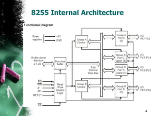
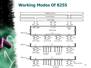
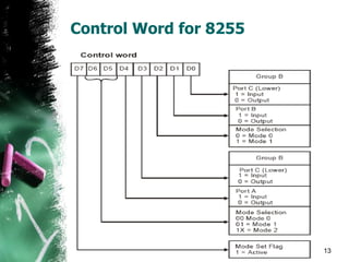
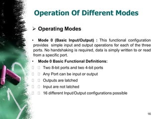
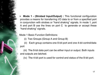
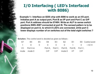
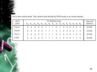
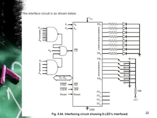
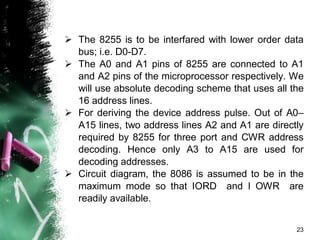
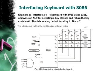
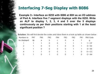
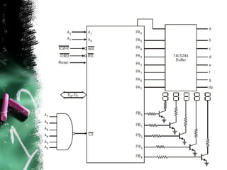
I/O Interfacing of 8086
Using 8255
2
ROAD MAP
• 8255 Internal Architecture
• Working Modes Of 8255
• Control Word Of 8255 PPI
• BSR Mode Control Word
• Operation Of Different 8255 Modes
• Interfacing Examples Using 8255 PPI
8255 Programmable Peripheral Interface
Description
 The Intel 82C55A is a general purpose programmable I/O
device which may be used with many different
microprocessors.
 There are 24 I/O pins which may be individually
programmed in 2 groups of 12 and used in 3 major modes of
operation.
 The high performance and industry standard configuration
of the 82C55A make it compatible with the 8086.
3
8255 Internal Architecture
4
 Data Bus Buffer
This three-state bi-directional 8-bit buffer is used to
interface the 82C55A to the system data bus. Data is
transmitted or received by the buffer upon execution
of input or output instructions by the CPU. Control
words and status information are also transferred
through the data bus buffer.
 Read/Write and Control Logic
The function of this block is to manage all of the
internal and external transfers of both Data and
Control or Status words. It accepts inputs from the
CPU Address and Control busses accepts inputs from
the CPU Address and Control busses and in turn,
issues commands to both of the Control Groups.
5
 (A0 and A1) Port Select 0 and Port Select 1 :
These input signals, in conjunction with the RD
and WR inputs, control the selection of one of the
three ports or the control word register. They are
normally connected to the least significant bits of
the address bus (A0 and A1).
 (CS) Chip Select : A “low” on this input pin
enables the communication between the 82C55A
and the CPU.
6
 (RD) Read : A “low” on this input pin enables
82C55A to send the data or status information to
the CPU on the data bus. In essence, it allows the
CPU to “read from” the 82C55A.
 (WR) Write : A “low” on this input pin enables
the CPU to write data or control words into the
82C55A.
7
 (RESET) Reset : A “high” on this input
initializes the control register to 9Bh and all ports
(A, B, C) are set to the input mode. “Bus hold”
devices internal to the 82C55A will hold the I/O
port inputs to a logic “1” state with a maximum
hold current of 400mA.
8
Working Modes Of 8255
 Mode Selection
There are three basic modes of operation than can be
selected by the system software:
• Mode 0 - Basic Input/Output
• Mode 1 - Strobed Input/Output
• Mode 2 - Bi-directional Bus
9
• When the reset input goes “high”, all ports will be set to
the input mode with all 24 port lines held at a logic “one”
level by internal bus hold devices.
• After the reset is removed, the 82C55A can remain in the
input mode with no additional initialization required
• During the execution of the system program, any of the
other modes may be selected using a single output
instruction. This allows a single 82C55A to service a
variety of peripheral devices with a simple software
maintenance routine.
• Any port programmed as an output port is initialized to all
zeros when the control word is written.
10
Working Modes Of 8255
11/30/2007 11
Er.Nikhil Marriwala:
UIET Ecn 5th Sem
 The modes for Port A and Port B can be separately
defined, while Port C is divided into two portions as
required by the Port A and Port B definitions.
 For instance: Group B can be programmed in Mode
0 to monitor simple switch closings or display
computational results, Group A could be
programmed in Mode 1 to monitor a keyboard or tape
reader on an interrupt-driven basis.
12
Control Word for 8255
11/30/2007 13
Er.Nikhil Marriwala:
UIET Ecn 5th Sem
BSR Mode For 8255
 Single Bit Set/Reset Feature
• Any of the eight bits of Port C can be Set or
Reset using a single Output instruction. This
feature reduces software requirements in control-
based applications. operation just as if they were
output ports.
• When Port C is being used as status/control for
Port A or B, these bits can be set or reset by
using the Bit Set/Reset.
14
BSR Control Word
15
Operation Of Different Modes
 Operating Modes
• Mode 0 (Basic Input/Output) : This functional configuration
provides simple input and output operations for each of the three
ports. No handshaking is required, data is simply written to or read
from a specific port.
• Mode 0 Basic Functional Definitions:
  Two 8-bit ports and two 4-bit ports
  Any Port can be input or output
  Outputs are latched
  Input are not latched
  16 different Input/Output configurations possible
16
 Mode 1 - (Strobed Input/Output) : This functional configuration
provides a means for transferring I/O data to or from a specified port
in conjunction with strobes or “hand shaking” signals. In mode 1, port
A and port B use the lines on port C to generate or accept these
“hand shaking” signals.
Mode 1 Basic Function Definitions:
(i) Two Groups (Group A and Group B)
(ii) Each group contains one 8-bit port and one 4-bit control/data
port
(iii) The 8-bit data port can be either input or output. Both inputs
and outputs are latched.
(iv) The 4-bit port is used for control and status of the 8-bit port.
17
 Mode 2 Basic Functional Definitions :
(i) Used in Group A only
(ii) One 8-bit, bi-directional bus Port (Port A)
and a 5-bit control Por t (Por t C)
(iii) Both inputs and outputs are latched
(iv)The 5-bit control port (Port C) is used for
control and status for the 8-bit, bi-directional bus
port (Por t A)
18
I/O Interfacing ( LED’s Interfaced
with 8086)
Example 1:- Interface an 8255 chip with 8086 to work as an I/O port.
Initialize port A as output port, Port B as I/P port and Port C as O/P
port. Port A address should be 0740H. Write an ALP to sense switch
positions SW0–SW7 connected at port B. The sensed pattern is to be
displayed on port A, to which 8 LED's are connected, while port C
lower displays number of on switches out of the total eight switches ?
19
20
21
22
 The 8255 is to be interfared with lower order data
bus; i.e. D0-D7.
 The A0 and A1 pins of 8255 are connected to A1
and A2 pins of the microprocessor respectively. We
will use absolute decoding scheme that uses all the
16 address lines.
 For deriving the device address pulse. Out of A0–
A15 lines, two address lines A2 and A1 are directly
required by 8255 for three port and CWR address
decoding. Hence only A3 to A15 are used for
decoding addresses.
 Circuit diagram, the 8086 is assumed to be in the
maximum mode so that IORD and I OWR are
readily available.
23
Interfacing Keyboard with 8086
Example 2:-. Interface a 4 4 keyboard with 8086 using 8255,
and write an ALP for detecting a key closure and return the key
code in AL. The debouncing period for a key in 20 ms ?
•
24
• Here we use port A as output port for selecting
a row of keys while port B is used as an input port
for sensing a closed key.
• Hence the keyboard lines are selected one by
one through Port A and the Port B lines are polled
continuously till a key closure is sensed.
• The higher order lines of Port A and Port B are
left unused. The flow chart of the ALP is as
shown below :
25
26
 We suppose that we use simple mechanical switches.
For keyboard, then to get the meaningful data from a
keyboard requires three steps :
• (1) Detect a key press
•
• (2) Debounce the key press
•
• (3) Encode the key press
 The three tasks can be done with a hardware, software
or a combination of the two.
 The rows of the matrix are connected to four output
port lines. The column line of the matrix are connected to
four input port lines
27
Interfacing 7-Seg Display with 8086
Example 3:- Interface an 8255 with 8086 at 80H as an I/O address
of Port A. Interface five 7 segment displays with the 8255. Write
an ALP to display 1, 2, 3, 4 and 5 over the 5 displays
continuously as per their positions starting with 1 at the least
significant position ?
28
29
THANKS!
For more Notes Follow http://www.edutechlearners.com

8255 & IO Interfacing.pdf

  • 1.
    I/O Interfacing of8086 Using 8255
  • 2.
    2 ROAD MAP • 8255Internal Architecture • Working Modes Of 8255 • Control Word Of 8255 PPI • BSR Mode Control Word • Operation Of Different 8255 Modes • Interfacing Examples Using 8255 PPI
  • 3.
    8255 Programmable PeripheralInterface Description  The Intel 82C55A is a general purpose programmable I/O device which may be used with many different microprocessors.  There are 24 I/O pins which may be individually programmed in 2 groups of 12 and used in 3 major modes of operation.  The high performance and industry standard configuration of the 82C55A make it compatible with the 8086. 3
  • 4.
  • 5.
     Data BusBuffer This three-state bi-directional 8-bit buffer is used to interface the 82C55A to the system data bus. Data is transmitted or received by the buffer upon execution of input or output instructions by the CPU. Control words and status information are also transferred through the data bus buffer.  Read/Write and Control Logic The function of this block is to manage all of the internal and external transfers of both Data and Control or Status words. It accepts inputs from the CPU Address and Control busses accepts inputs from the CPU Address and Control busses and in turn, issues commands to both of the Control Groups. 5
  • 6.
     (A0 andA1) Port Select 0 and Port Select 1 : These input signals, in conjunction with the RD and WR inputs, control the selection of one of the three ports or the control word register. They are normally connected to the least significant bits of the address bus (A0 and A1).  (CS) Chip Select : A “low” on this input pin enables the communication between the 82C55A and the CPU. 6
  • 7.
     (RD) Read: A “low” on this input pin enables 82C55A to send the data or status information to the CPU on the data bus. In essence, it allows the CPU to “read from” the 82C55A.  (WR) Write : A “low” on this input pin enables the CPU to write data or control words into the 82C55A. 7
  • 8.
     (RESET) Reset: A “high” on this input initializes the control register to 9Bh and all ports (A, B, C) are set to the input mode. “Bus hold” devices internal to the 82C55A will hold the I/O port inputs to a logic “1” state with a maximum hold current of 400mA. 8
  • 9.
    Working Modes Of8255  Mode Selection There are three basic modes of operation than can be selected by the system software: • Mode 0 - Basic Input/Output • Mode 1 - Strobed Input/Output • Mode 2 - Bi-directional Bus 9
  • 10.
    • When thereset input goes “high”, all ports will be set to the input mode with all 24 port lines held at a logic “one” level by internal bus hold devices. • After the reset is removed, the 82C55A can remain in the input mode with no additional initialization required • During the execution of the system program, any of the other modes may be selected using a single output instruction. This allows a single 82C55A to service a variety of peripheral devices with a simple software maintenance routine. • Any port programmed as an output port is initialized to all zeros when the control word is written. 10
  • 11.
    Working Modes Of8255 11/30/2007 11 Er.Nikhil Marriwala: UIET Ecn 5th Sem
  • 12.
     The modesfor Port A and Port B can be separately defined, while Port C is divided into two portions as required by the Port A and Port B definitions.  For instance: Group B can be programmed in Mode 0 to monitor simple switch closings or display computational results, Group A could be programmed in Mode 1 to monitor a keyboard or tape reader on an interrupt-driven basis. 12
  • 13.
    Control Word for8255 11/30/2007 13 Er.Nikhil Marriwala: UIET Ecn 5th Sem
  • 14.
    BSR Mode For8255  Single Bit Set/Reset Feature • Any of the eight bits of Port C can be Set or Reset using a single Output instruction. This feature reduces software requirements in control- based applications. operation just as if they were output ports. • When Port C is being used as status/control for Port A or B, these bits can be set or reset by using the Bit Set/Reset. 14
  • 15.
  • 16.
    Operation Of DifferentModes  Operating Modes • Mode 0 (Basic Input/Output) : This functional configuration provides simple input and output operations for each of the three ports. No handshaking is required, data is simply written to or read from a specific port. • Mode 0 Basic Functional Definitions:   Two 8-bit ports and two 4-bit ports   Any Port can be input or output   Outputs are latched   Input are not latched   16 different Input/Output configurations possible 16
  • 17.
     Mode 1- (Strobed Input/Output) : This functional configuration provides a means for transferring I/O data to or from a specified port in conjunction with strobes or “hand shaking” signals. In mode 1, port A and port B use the lines on port C to generate or accept these “hand shaking” signals. Mode 1 Basic Function Definitions: (i) Two Groups (Group A and Group B) (ii) Each group contains one 8-bit port and one 4-bit control/data port (iii) The 8-bit data port can be either input or output. Both inputs and outputs are latched. (iv) The 4-bit port is used for control and status of the 8-bit port. 17
  • 18.
     Mode 2Basic Functional Definitions : (i) Used in Group A only (ii) One 8-bit, bi-directional bus Port (Port A) and a 5-bit control Por t (Por t C) (iii) Both inputs and outputs are latched (iv)The 5-bit control port (Port C) is used for control and status for the 8-bit, bi-directional bus port (Por t A) 18
  • 19.
    I/O Interfacing (LED’s Interfaced with 8086) Example 1:- Interface an 8255 chip with 8086 to work as an I/O port. Initialize port A as output port, Port B as I/P port and Port C as O/P port. Port A address should be 0740H. Write an ALP to sense switch positions SW0–SW7 connected at port B. The sensed pattern is to be displayed on port A, to which 8 LED's are connected, while port C lower displays number of on switches out of the total eight switches ? 19
  • 20.
  • 21.
  • 22.
  • 23.
     The 8255is to be interfared with lower order data bus; i.e. D0-D7.  The A0 and A1 pins of 8255 are connected to A1 and A2 pins of the microprocessor respectively. We will use absolute decoding scheme that uses all the 16 address lines.  For deriving the device address pulse. Out of A0– A15 lines, two address lines A2 and A1 are directly required by 8255 for three port and CWR address decoding. Hence only A3 to A15 are used for decoding addresses.  Circuit diagram, the 8086 is assumed to be in the maximum mode so that IORD and I OWR are readily available. 23
  • 24.
    Interfacing Keyboard with8086 Example 2:-. Interface a 4 4 keyboard with 8086 using 8255, and write an ALP for detecting a key closure and return the key code in AL. The debouncing period for a key in 20 ms ? • 24
  • 25.
    • Here weuse port A as output port for selecting a row of keys while port B is used as an input port for sensing a closed key. • Hence the keyboard lines are selected one by one through Port A and the Port B lines are polled continuously till a key closure is sensed. • The higher order lines of Port A and Port B are left unused. The flow chart of the ALP is as shown below : 25
  • 26.
  • 27.
     We supposethat we use simple mechanical switches. For keyboard, then to get the meaningful data from a keyboard requires three steps : • (1) Detect a key press • • (2) Debounce the key press • • (3) Encode the key press  The three tasks can be done with a hardware, software or a combination of the two.  The rows of the matrix are connected to four output port lines. The column line of the matrix are connected to four input port lines 27
  • 28.
    Interfacing 7-Seg Displaywith 8086 Example 3:- Interface an 8255 with 8086 at 80H as an I/O address of Port A. Interface five 7 segment displays with the 8255. Write an ALP to display 1, 2, 3, 4 and 5 over the 5 displays continuously as per their positions starting with 1 at the least significant position ? 28
  • 29.
  • 30.
    THANKS! For more NotesFollow http://www.edutechlearners.com