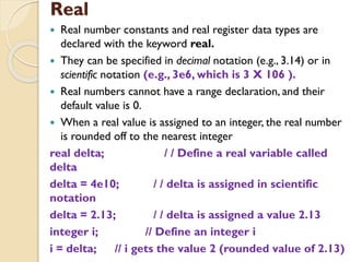
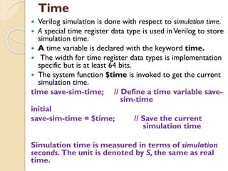
This document provides an overview of various data types and constructs in Verilog hardware description language (HDL), including strings, identifiers, keywords, nets, registers, vectors, integers, real numbers, time, arrays, memories, and parameters. It defines each concept, provides examples of declarations and usage, and references additional resources for further reading. The key topics covered are data representation, variable types, module constructs, and modeling memory in Verilog HDL.
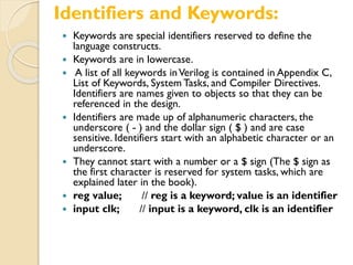
![ reg [8*18:1] string-value;
//Declare a variable that is l8 bytes wide
Initial string-value = "HelloVerilogWorld";
// String can be stored
// in variable](https://image.slidesharecdn.com/vhdldatatypes-210618130320/85/VHDL-data-types-5-320.jpg)
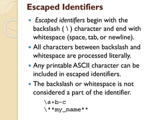
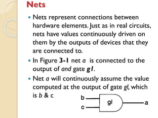

![Vectors
Nets or reg data types can be declared as vectors (multiple
bit widths).
If bit width is not specified, the default is scalar (l-bit).
Vectors can be declared at [high# : low#] or [low# : high#],
but the left number in the squared brackets is always the
most significant bit of the vector. In the example shown
above, bit 0 is the most significant bit of vector virtual-addr.
For the vector declarations shown above, it is possible to
address bits or parts of vectors.
wire a; / / scalar net variable, default
wire [7:0] bus; / / 8-bit bus
wire [31:0] busA,busB,busC; / / 3 buses of 32-bit
width.
reg clock; / / scalar register, default
reg [O : 40] virtual-addr; // vector register, virtual
address 41 bits wide](https://image.slidesharecdn.com/vhdldatatypes-210618130320/85/VHDL-data-types-14-320.jpg)
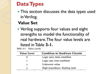
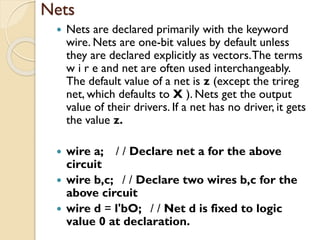
![Vectors: Accessing elements
Wire [7:0] busA /8 bit vector busA
busA[2] // 2nd bit of vector busA
busA[2:0] //Three least significant
bits of vector bus,
/* using bus[0:2] is illegal because the
significant bit should always be on the
left of a range specification*/](https://image.slidesharecdn.com/vhdldatatypes-210618130320/85/VHDL-data-types-15-320.jpg)
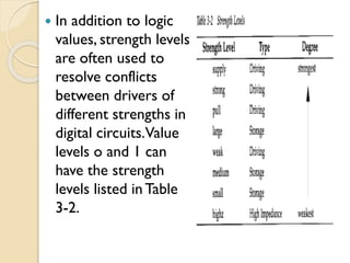
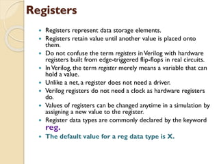
![Arrays
Arrays are allowed inVerilog for reg, integer, time, and vector register data
types. Arrays are not allowed for real variables.Arrays are accessed by <array-
name> [<subscript>l.
integer count[0:7]; / / an array of 8 count variables
reg bool[31:0 1] ; //Array of 32 one-bit boolean register variables
time chkqpoint[l:lOO]; //Array of 100 time checkpoint variables
reg [4 : 01 port-id[O : 71 ; //Array of 8port-ids; each port-id is 5 bits wide
integer matrix[4:0][4:0]; // 11legaldeclaration.Multidimensional
array
count[5] // 5th element of array of count variables
chk_point[100] //100th time check point value
port_id[3] //3rd element of port-id array.This is a 5-bit value.
A vector is a single element that is n-bits wide. On the other hand, arrays are
multiple elements that are l-bit or n-bits wide.](https://image.slidesharecdn.com/vhdldatatypes-210618130320/85/VHDL-data-types-19-320.jpg)
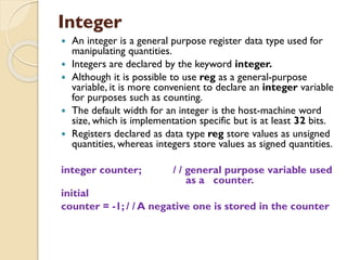
![Memories
In digital simulation, one often needs to model
register files, RAMS, and ROMs.
Memories are modeled inVerilog simply as an array of
registers.
Each element of the array is known as a word. Each
word can be one or more bits.
It is important to differentiate between n l-bit
registers and one n-bit register.A particular word in
memory is obtained by using the address as a
memory array subscript.
reg memlbit[0:1023]; //~emory memlbit with 1K
l-bit words
reg [7 : 01 membyte [O : 10231]]; // memory
membyte with 1K 8-bit words (bytes)](https://image.slidesharecdn.com/vhdldatatypes-210618130320/85/VHDL-data-types-20-320.jpg)