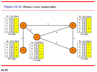
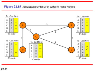
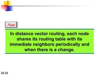
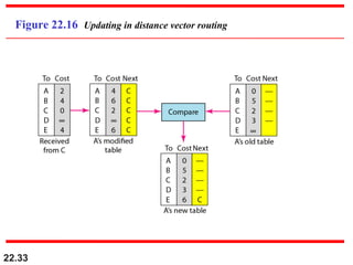
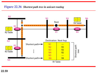
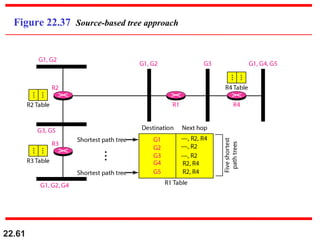
22.1
Chapter 22
Network Layer:
Delivery, Forwarding,
and Routing
Copyright © The McGraw-Hill Companies, Inc. Permission required for reproduction or display.
22.2
22-1 DELIVERY22-1 DELIVERY
The network layer supervises the handling of theThe network layer supervises the handling of the
packets by the underlying physical networks. Wepackets by the underlying physical networks. We
define this handling as the delivery of a packet.define this handling as the delivery of a packet.
Direct Versus Indirect Delivery
Topics discussed in this section:Topics discussed in this section:
22.3
Figure 22.1 Direct and indirect delivery
22.4
22-2 FORWARDING22-2 FORWARDING
Forwarding means to place the packet in its route toForwarding means to place the packet in its route to
its destination. Forwarding requires a host or a routerits destination. Forwarding requires a host or a router
to have a routing table. When a host has a packet toto have a routing table. When a host has a packet to
send or when a router has received a packet to besend or when a router has received a packet to be
forwarded, it looks at this table to find the route to theforwarded, it looks at this table to find the route to the
final destination.final destination.
Forwarding Techniques
Forwarding Process
Routing Table
Topics discussed in this section:Topics discussed in this section:
22.5
Figure 22.2 Route method versus next-hop method
22.6
Figure 22.3 Host-specific versus network-specific method
22.7
Figure 22.4 Default method
22.8
Figure 22.5 Simplified forwarding module in classless address
22.9
In classless addressing, we need at
least four columns in a routing table.
Note
22.10
Make a routing table for router R1, using the
configuration in Figure 22.6.
Example 22.1
Solution
Table 22.1 shows the corresponding table.
22.11
Figure 22.6 Configuration for Example 22.1
22.12
Table 22.1 Routing table for router R1 in Figure 22.6
22.13
Show the forwarding process if a packet arrives at R1 in
Figure 22.6 with the destination address 180.70.65.140.
Example 22.2
Solution
The router performs the following steps:
1. The first mask (/26) is applied to the destination address.
The result is 180.70.65.128, which does not match the
corresponding network address.
2. The second mask (/25) is applied to the destination
address. The result is 180.70.65.128, which matches the
corresponding network address. The next-hop address
and the interface number m0 are passed to ARP for
further processing.
22.14
Show the forwarding process if a packet arrives at R1 in
Figure 22.6 with the destination address 201.4.22.35.
Example 22.3
Solution
The router performs the following steps:
1. The first mask (/26) is applied to the destination
address. The result is 201.4.22.0, which does not
match the corresponding network address.
2. The second mask (/25) is applied to the destination
address. The result is 201.4.22.0, which does not
match the corresponding network address (row 2).
22.15
Example 22.3 (continued)
3. The third mask (/24) is applied to the destination
address. The result is 201.4.22.0, which matches the
corresponding network address. The destination
address of the packet and the interface number m3 are
passed to ARP.
22.16
Show the forwarding process if a packet arrives at R1 in
Figure 22.6 with the destination address 18.24.32.78.
Example 22.4
Solution
This time all masks are applied, one by one, to the
destination address, but no matching network address is
found. When it reaches the end of the table, the module
gives the next-hop address 180.70.65.200 and interface
number m2 to ARP. This is probably an outgoing
package that needs to be sent, via the default router, to
someplace else in the Internet.
22.17
Figure 22.7 Address aggregation
22.18
Figure 22.8 Longest mask matching
22.19
As an example of hierarchical routing, let us consider
Figure 22.9. A regional ISP is granted 16,384 addresses
starting from 120.14.64.0. The regional ISP has decided
to divide this block into four subblocks, each with 4096
addresses. Three of these subblocks are assigned to three
local ISPs; the second subblock is reserved for future use.
Note that the mask for each block is /20 because the
original block with mask /18 is divided into 4 blocks.
Example 22.5
The first local ISP has divided its assigned subblock into
8 smaller blocks and assigned each to a small ISP. Each
small ISP provides services to 128 households, each using
four addresses.
22.20
The second local ISP has divided its block into 4 blocks
and has assigned the addresses to four large
organizations.
Example 22.5 (continued)
There is a sense of hierarchy in this configuration. All
routers in the Internet send a packet with destination
address 120.14.64.0 to 120.14.127.255 to the regional
ISP.
The third local ISP has divided its block into 16 blocks
and assigned each block to a small organization. Each
small organization has 256 addresses, and the mask is /
24.
22.21
Figure 22.9 Hierarchical routing with ISPs
22.22
Figure 22.10 Common fields in a routing table
22.23
One utility that can be used to find the contents of a
routing table for a host or router is netstat in UNIX or
LINUX. The next slide shows the list of the contents of a
default server. We have used two options, r and n. The
option r indicates that we are interested in the routing
table, and the option n indicates that we are looking for
numeric addresses. Note that this is a routing table for a
host, not a router. Although we discussed the routing table
for a router throughout the chapter, a host also needs a
routing table.
Example 22.6
22.24
Example 22.6 (continued)
The destination column here defines the network address.
The term gateway used by UNIX is synonymous with
router. This column actually defines the address of the next
hop. The value 0.0.0.0 shows that the delivery is direct. The
last entry has a flag of G, which means that the destination
can be reached through a router (default router). The Iface
defines the interface.
22.25
Example 22.6 (continued)
More information about the IP address and physical
address of the server can be found by using the ifconfig
command on the given interface (eth0).
22.26
Figure 22.11 Configuration of the server for Example 22.6
22.27
22-3 UNICAST ROUTING PROTOCOLS22-3 UNICAST ROUTING PROTOCOLS
A routing table can be either static or dynamic. AA routing table can be either static or dynamic. A
static table is one with manual entries. A dynamicstatic table is one with manual entries. A dynamic
table is one that is updated automatically when there istable is one that is updated automatically when there is
a change somewhere in the Internet. A routinga change somewhere in the Internet. A routing
protocol is a combination of rules and procedures thatprotocol is a combination of rules and procedures that
lets routers in the Internet inform each other oflets routers in the Internet inform each other of
changes.changes.
Optimization
Intra- and Interdomain Routing
Distance Vector Routing and RIP
Link State Routing and OSPF
Path Vector Routing and BGP
Topics discussed in this section:Topics discussed in this section:
22.28
Figure 22.12 Autonomous systems
22.29
Figure 22.13 Popular routing protocols
22.30
Figure 22.14 Distance vector routing tables
22.31
Figure 22.15 Initialization of tables in distance vector routing
22.32
In distance vector routing, each node
shares its routing table with its
immediate neighbors periodically and
when there is a change.
Note
22.33
Figure 22.16 Updating in distance vector routing
22.34
Figure 22.17 Two-node instability
22.35
Figure 22.18 Three-node instability
22.36
Figure 22.19 Example of a domain using RIP
22.37
Figure 22.20 Concept of link state routing
22.38
Figure 22.21 Link state knowledge
22.39
Figure 22.22 Dijkstra algorithm
22.40
Figure 22.23 Example of formation of shortest path tree
22.41
Table 22.2 Routing table for node A
22.42
Figure 22.24 Areas in an autonomous system
22.43
Figure 22.25 Types of links
22.44
Figure 22.26 Point-to-point link
22.45
Figure 22.27 Transient link
22.46
Figure 22.28 Stub link
22.47
Figure 22.29 Example of an AS and its graphical representation in OSPF
22.48
Figure 22.30 Initial routing tables in path vector routing
22.49
Figure 22.31 Stabilized tables for three autonomous systems
22.50
Figure 22.32 Internal and external BGP sessions
22.51
22-4 MULTICAST ROUTING PROTOCOLS22-4 MULTICAST ROUTING PROTOCOLS
In this section, we discuss multicasting and multicastIn this section, we discuss multicasting and multicast
routing protocols.routing protocols.
Unicast, Multicast, and Broadcast
Applications
Multicast Routing
Routing Protocols
Topics discussed in this section:Topics discussed in this section:
22.52
Figure 22.33 Unicasting
22.53
In unicasting, the router forwards the
received packet through
only one of its interfaces.
Note
22.54
Figure 22.34 Multicasting
22.55
In multicasting, the router may
forward the received packet
through several of its interfaces.
Note
22.56
Figure 22.35 Multicasting versus multiple unicasting
22.57
Emulation of multicasting through
multiple unicasting is not efficient
and may create long delays,
particularly with a large group.
Note
22.58
In unicast routing, each router in the
domain has a table that defines
a shortest path tree to possible
destinations.
Note
22.59
Figure 22.36 Shortest path tree in unicast routing
22.60
In multicast routing, each involved
router needs to construct
a shortest path tree for each group.
Note
22.61
Figure 22.37 Source-based tree approach
22.62
In the source-based tree approach, each
router needs to have one shortest path
tree for each group.
Note
22.63
Figure 22.38 Group-shared tree approach
22.64
In the group-shared tree approach, only
the core router, which has a shortest
path tree for each group, is involved in
multicasting.
Note
22.65
Figure 22.39 Taxonomy of common multicast protocols
22.66
Multicast link state routing uses the
source-based tree approach.
Note
22.67
Flooding broadcasts packets, but
creates loops in the systems.
Note
22.68
RPF eliminates the loop in the
flooding process.
Note
22.69
Figure 22.40 Reverse path forwarding (RPF)
22.70
Figure 22.41 Problem with RPF
22.71
Figure 22.42 RPF Versus RPB
22.72
RPB creates a shortest path broadcast
tree from the source to each destination.
It guarantees that each destination
receives one and only one copy
of the packet.
Note
22.73
Figure 22.43 RPF, RPB, and RPM
22.74
RPM adds pruning and grafting to RPB
to create a multicast shortest
path tree that supports dynamic
membership changes.
Note
22.75
Figure 22.44 Group-shared tree with rendezvous router
22.76
Figure 22.45 Sending a multicast packet to the rendezvous router
22.77
In CBT, the source sends the multicast
packet (encapsulated in a unicast
packet) to the core router. The core
router decapsulates the packet and
forwards it to all interested interfaces.
Note
22.78
PIM-DM is used in a dense multicast
environment, such as a LAN.
Note
22.79
PIM-DM uses RPF and pruning and
grafting strategies to handle
multicasting.
However, it is independent of the
underlying unicast protocol.
Note
22.80
PIM-SM is used in a sparse multicast
environment such as a WAN.
Note
22.81
PIM-SM is similar to CBT but uses a
simpler procedure.
Note
22.82
Figure 22.46 Logical tunneling
22.83
Figure 22.47 MBONE

22 Network Layer_Delivery_forwarding_and_Routing

  • 1.
    22.1 Chapter 22 Network Layer: Delivery,Forwarding, and Routing Copyright © The McGraw-Hill Companies, Inc. Permission required for reproduction or display.
  • 2.
    22.2 22-1 DELIVERY22-1 DELIVERY Thenetwork layer supervises the handling of theThe network layer supervises the handling of the packets by the underlying physical networks. Wepackets by the underlying physical networks. We define this handling as the delivery of a packet.define this handling as the delivery of a packet. Direct Versus Indirect Delivery Topics discussed in this section:Topics discussed in this section:
  • 3.
    22.3 Figure 22.1 Directand indirect delivery
  • 4.
    22.4 22-2 FORWARDING22-2 FORWARDING Forwardingmeans to place the packet in its route toForwarding means to place the packet in its route to its destination. Forwarding requires a host or a routerits destination. Forwarding requires a host or a router to have a routing table. When a host has a packet toto have a routing table. When a host has a packet to send or when a router has received a packet to besend or when a router has received a packet to be forwarded, it looks at this table to find the route to theforwarded, it looks at this table to find the route to the final destination.final destination. Forwarding Techniques Forwarding Process Routing Table Topics discussed in this section:Topics discussed in this section:
  • 5.
    22.5 Figure 22.2 Routemethod versus next-hop method
  • 6.
    22.6 Figure 22.3 Host-specificversus network-specific method
  • 7.
  • 8.
    22.8 Figure 22.5 Simplifiedforwarding module in classless address
  • 9.
    22.9 In classless addressing,we need at least four columns in a routing table. Note
  • 10.
    22.10 Make a routingtable for router R1, using the configuration in Figure 22.6. Example 22.1 Solution Table 22.1 shows the corresponding table.
  • 11.
  • 12.
    22.12 Table 22.1 Routingtable for router R1 in Figure 22.6
  • 13.
    22.13 Show the forwardingprocess if a packet arrives at R1 in Figure 22.6 with the destination address 180.70.65.140. Example 22.2 Solution The router performs the following steps: 1. The first mask (/26) is applied to the destination address. The result is 180.70.65.128, which does not match the corresponding network address. 2. The second mask (/25) is applied to the destination address. The result is 180.70.65.128, which matches the corresponding network address. The next-hop address and the interface number m0 are passed to ARP for further processing.
  • 14.
    22.14 Show the forwardingprocess if a packet arrives at R1 in Figure 22.6 with the destination address 201.4.22.35. Example 22.3 Solution The router performs the following steps: 1. The first mask (/26) is applied to the destination address. The result is 201.4.22.0, which does not match the corresponding network address. 2. The second mask (/25) is applied to the destination address. The result is 201.4.22.0, which does not match the corresponding network address (row 2).
  • 15.
    22.15 Example 22.3 (continued) 3.The third mask (/24) is applied to the destination address. The result is 201.4.22.0, which matches the corresponding network address. The destination address of the packet and the interface number m3 are passed to ARP.
  • 16.
    22.16 Show the forwardingprocess if a packet arrives at R1 in Figure 22.6 with the destination address 18.24.32.78. Example 22.4 Solution This time all masks are applied, one by one, to the destination address, but no matching network address is found. When it reaches the end of the table, the module gives the next-hop address 180.70.65.200 and interface number m2 to ARP. This is probably an outgoing package that needs to be sent, via the default router, to someplace else in the Internet.
  • 17.
  • 18.
  • 19.
    22.19 As an exampleof hierarchical routing, let us consider Figure 22.9. A regional ISP is granted 16,384 addresses starting from 120.14.64.0. The regional ISP has decided to divide this block into four subblocks, each with 4096 addresses. Three of these subblocks are assigned to three local ISPs; the second subblock is reserved for future use. Note that the mask for each block is /20 because the original block with mask /18 is divided into 4 blocks. Example 22.5 The first local ISP has divided its assigned subblock into 8 smaller blocks and assigned each to a small ISP. Each small ISP provides services to 128 households, each using four addresses.
  • 20.
    22.20 The second localISP has divided its block into 4 blocks and has assigned the addresses to four large organizations. Example 22.5 (continued) There is a sense of hierarchy in this configuration. All routers in the Internet send a packet with destination address 120.14.64.0 to 120.14.127.255 to the regional ISP. The third local ISP has divided its block into 16 blocks and assigned each block to a small organization. Each small organization has 256 addresses, and the mask is / 24.
  • 21.
  • 22.
    22.22 Figure 22.10 Commonfields in a routing table
  • 23.
    22.23 One utility thatcan be used to find the contents of a routing table for a host or router is netstat in UNIX or LINUX. The next slide shows the list of the contents of a default server. We have used two options, r and n. The option r indicates that we are interested in the routing table, and the option n indicates that we are looking for numeric addresses. Note that this is a routing table for a host, not a router. Although we discussed the routing table for a router throughout the chapter, a host also needs a routing table. Example 22.6
  • 24.
    22.24 Example 22.6 (continued) Thedestination column here defines the network address. The term gateway used by UNIX is synonymous with router. This column actually defines the address of the next hop. The value 0.0.0.0 shows that the delivery is direct. The last entry has a flag of G, which means that the destination can be reached through a router (default router). The Iface defines the interface.
  • 25.
    22.25 Example 22.6 (continued) Moreinformation about the IP address and physical address of the server can be found by using the ifconfig command on the given interface (eth0).
  • 26.
    22.26 Figure 22.11 Configurationof the server for Example 22.6
  • 27.
    22.27 22-3 UNICAST ROUTINGPROTOCOLS22-3 UNICAST ROUTING PROTOCOLS A routing table can be either static or dynamic. AA routing table can be either static or dynamic. A static table is one with manual entries. A dynamicstatic table is one with manual entries. A dynamic table is one that is updated automatically when there istable is one that is updated automatically when there is a change somewhere in the Internet. A routinga change somewhere in the Internet. A routing protocol is a combination of rules and procedures thatprotocol is a combination of rules and procedures that lets routers in the Internet inform each other oflets routers in the Internet inform each other of changes.changes. Optimization Intra- and Interdomain Routing Distance Vector Routing and RIP Link State Routing and OSPF Path Vector Routing and BGP Topics discussed in this section:Topics discussed in this section:
  • 28.
  • 29.
    22.29 Figure 22.13 Popularrouting protocols
  • 30.
    22.30 Figure 22.14 Distancevector routing tables
  • 31.
    22.31 Figure 22.15 Initializationof tables in distance vector routing
  • 32.
    22.32 In distance vectorrouting, each node shares its routing table with its immediate neighbors periodically and when there is a change. Note
  • 33.
    22.33 Figure 22.16 Updatingin distance vector routing
  • 34.
  • 35.
  • 36.
    22.36 Figure 22.19 Exampleof a domain using RIP
  • 37.
    22.37 Figure 22.20 Conceptof link state routing
  • 38.
    22.38 Figure 22.21 Linkstate knowledge
  • 39.
  • 40.
    22.40 Figure 22.23 Exampleof formation of shortest path tree
  • 41.
    22.41 Table 22.2 Routingtable for node A
  • 42.
    22.42 Figure 22.24 Areasin an autonomous system
  • 43.
  • 44.
  • 45.
  • 46.
  • 47.
    22.47 Figure 22.29 Exampleof an AS and its graphical representation in OSPF
  • 48.
    22.48 Figure 22.30 Initialrouting tables in path vector routing
  • 49.
    22.49 Figure 22.31 Stabilizedtables for three autonomous systems
  • 50.
    22.50 Figure 22.32 Internaland external BGP sessions
  • 51.
    22.51 22-4 MULTICAST ROUTINGPROTOCOLS22-4 MULTICAST ROUTING PROTOCOLS In this section, we discuss multicasting and multicastIn this section, we discuss multicasting and multicast routing protocols.routing protocols. Unicast, Multicast, and Broadcast Applications Multicast Routing Routing Protocols Topics discussed in this section:Topics discussed in this section:
  • 52.
  • 53.
    22.53 In unicasting, therouter forwards the received packet through only one of its interfaces. Note
  • 54.
  • 55.
    22.55 In multicasting, therouter may forward the received packet through several of its interfaces. Note
  • 56.
    22.56 Figure 22.35 Multicastingversus multiple unicasting
  • 57.
    22.57 Emulation of multicastingthrough multiple unicasting is not efficient and may create long delays, particularly with a large group. Note
  • 58.
    22.58 In unicast routing,each router in the domain has a table that defines a shortest path tree to possible destinations. Note
  • 59.
    22.59 Figure 22.36 Shortestpath tree in unicast routing
  • 60.
    22.60 In multicast routing,each involved router needs to construct a shortest path tree for each group. Note
  • 61.
  • 62.
    22.62 In the source-basedtree approach, each router needs to have one shortest path tree for each group. Note
  • 63.
  • 64.
    22.64 In the group-sharedtree approach, only the core router, which has a shortest path tree for each group, is involved in multicasting. Note
  • 65.
    22.65 Figure 22.39 Taxonomyof common multicast protocols
  • 66.
    22.66 Multicast link staterouting uses the source-based tree approach. Note
  • 67.
    22.67 Flooding broadcasts packets,but creates loops in the systems. Note
  • 68.
    22.68 RPF eliminates theloop in the flooding process. Note
  • 69.
    22.69 Figure 22.40 Reversepath forwarding (RPF)
  • 70.
  • 71.
  • 72.
    22.72 RPB creates ashortest path broadcast tree from the source to each destination. It guarantees that each destination receives one and only one copy of the packet. Note
  • 73.
  • 74.
    22.74 RPM adds pruningand grafting to RPB to create a multicast shortest path tree that supports dynamic membership changes. Note
  • 75.
    22.75 Figure 22.44 Group-sharedtree with rendezvous router
  • 76.
    22.76 Figure 22.45 Sendinga multicast packet to the rendezvous router
  • 77.
    22.77 In CBT, thesource sends the multicast packet (encapsulated in a unicast packet) to the core router. The core router decapsulates the packet and forwards it to all interested interfaces. Note
  • 78.
    22.78 PIM-DM is usedin a dense multicast environment, such as a LAN. Note
  • 79.
    22.79 PIM-DM uses RPFand pruning and grafting strategies to handle multicasting. However, it is independent of the underlying unicast protocol. Note
  • 80.
    22.80 PIM-SM is usedin a sparse multicast environment such as a WAN. Note
  • 81.
    22.81 PIM-SM is similarto CBT but uses a simpler procedure. Note
  • 82.
  • 83.