22.2
22-1 DELIVERY
22-1 DELIVERY
Thenetwork layer supervises the handling of the
The network layer supervises the handling of the
packets by the underlying physical networks. We
packets by the underlying physical networks. We
define this handling as the delivery of a packet.
define this handling as the delivery of a packet.
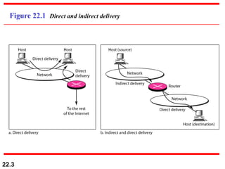
Direct Versus Indirect Delivery
Topics discussed in this section:
Topics discussed in this section:
22.4
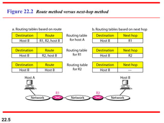
22-2 FORWARDING
22-2 FORWARDING
Forwardingmeans to place the packet in its route to
Forwarding means to place the packet in its route to
its destination. Forwarding requires a host or a router
its destination. Forwarding requires a host or a router
to have a routing table. When a host has a packet to
to have a routing table. When a host has a packet to
send or when a router has received a packet to be
send or when a router has received a packet to be
forwarded, it looks at this table to find the route to the
forwarded, it looks at this table to find the route to the
final destination.
final destination.
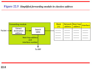
Forwarding Techniques
Forwarding Process
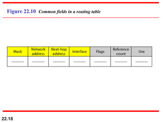
Routing Table
Topics discussed in this section:
Topics discussed in this section:
22.12
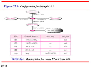
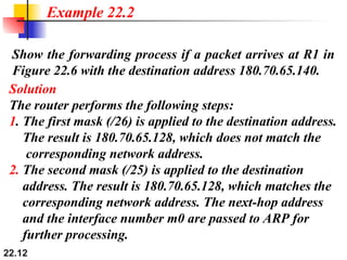
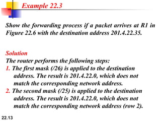
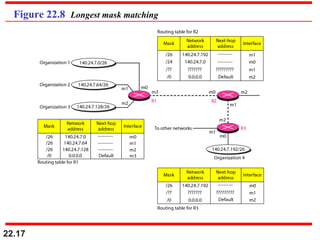
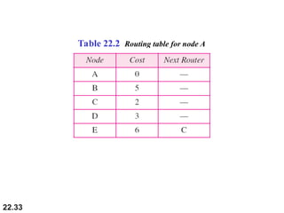
Show the forwardingprocess if a packet arrives at R1 in
Figure 22.6 with the destination address 180.70.65.140.
Example 22.2
Solution
The router performs the following steps:
1. The first mask (/26) is applied to the destination address.
The result is 180.70.65.128, which does not match the
corresponding network address.
2. The second mask (/25) is applied to the destination
address. The result is 180.70.65.128, which matches the
corresponding network address. The next-hop address
and the interface number m0 are passed to ARP for
further processing.
13.
22.13
Show the forwardingprocess if a packet arrives at R1 in
Figure 22.6 with the destination address 201.4.22.35.
Example 22.3
Solution
The router performs the following steps:
1. The first mask (/26) is applied to the destination
address. The result is 201.4.22.0, which does not
match the corresponding network address.
2. The second mask (/25) is applied to the destination
address. The result is 201.4.22.0, which does not
match the corresponding network address (row 2).
14.
22.14
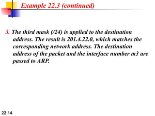
Example 22.3 (continued)
3.The third mask (/24) is applied to the destination
address. The result is 201.4.22.0, which matches the
corresponding network address. The destination
address of the packet and the interface number m3 are
passed to ARP.
15.
22.15
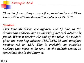
Show the forwardingprocess if a packet arrives at R1 in
Figure 22.6 with the destination address 18.24.32.78.
Example 22.4
Solution
This time all masks are applied, one by one, to the
destination address, but no matching network address is
found. When it reaches the end of the table, the module
gives the next-hop address 180.70.65.200 and interface
number m2 to ARP. This is probably an outgoing
package that needs to be sent, via the default router, to
someplace else in the Internet.
22.19
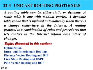
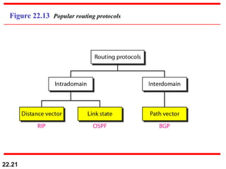
22-3 UNICAST ROUTINGPROTOCOLS
22-3 UNICAST ROUTING PROTOCOLS
A routing table can be either static or dynamic. A
A routing table can be either static or dynamic. A
static table is one with manual entries. A dynamic
static table is one with manual entries. A dynamic
table is one that is updated automatically when there is
table is one that is updated automatically when there is
a change somewhere in the Internet. A routing
a change somewhere in the Internet. A routing
protocol is a combination of rules and procedures that
protocol is a combination of rules and procedures that
lets routers in the Internet inform each other of
lets routers in the Internet inform each other of
changes.
changes.
Optimization
Intra- and Interdomain Routing
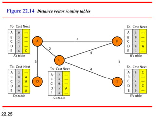
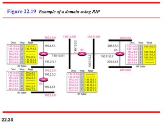
Distance Vector Routing and RIP
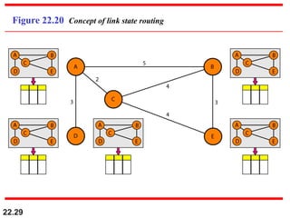
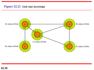
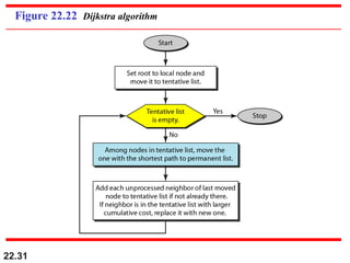
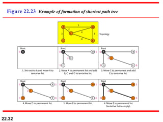
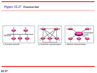
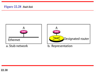
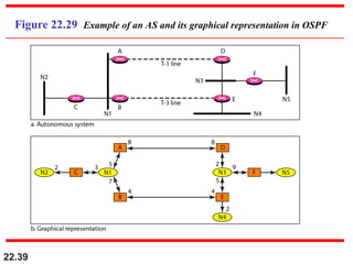
Link State Routing and OSPF
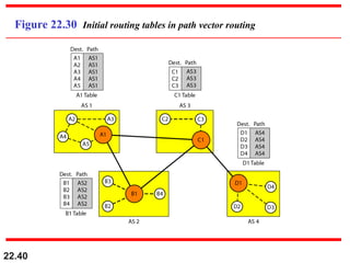
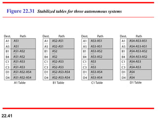
Path Vector Routing and BGP
Topics discussed in this section:
Topics discussed in this section: