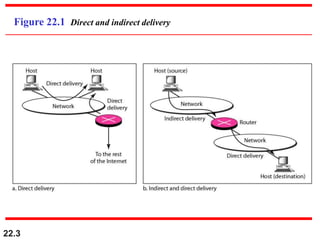
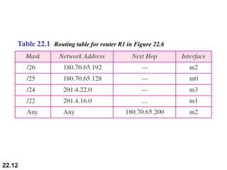
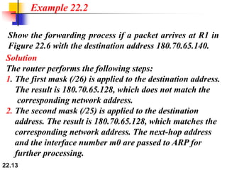
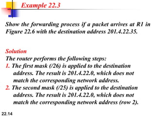
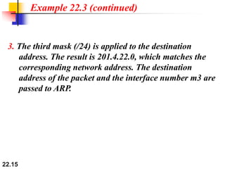
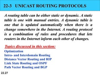
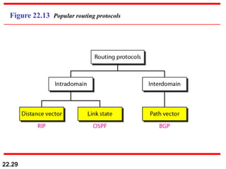
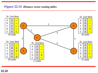
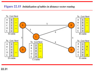
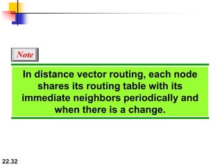
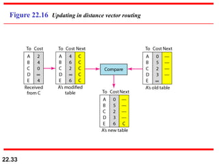
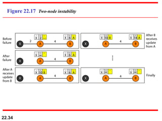
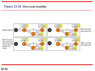
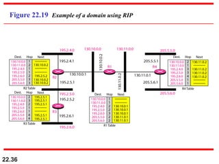
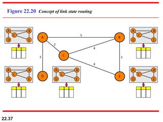
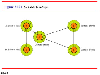
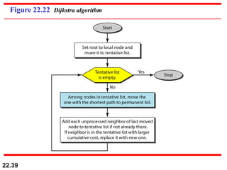
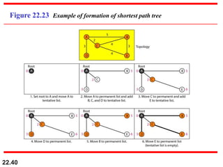
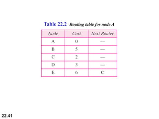
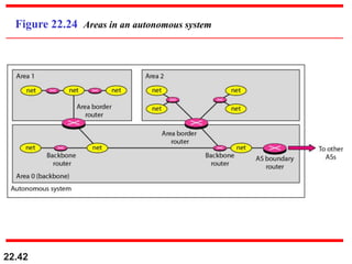
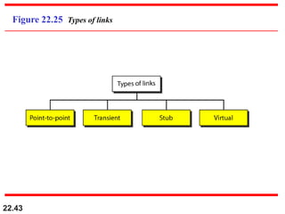
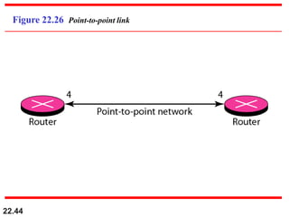
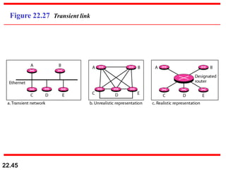
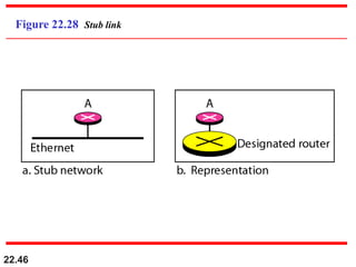
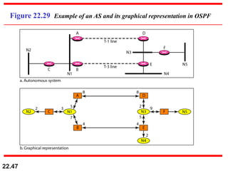
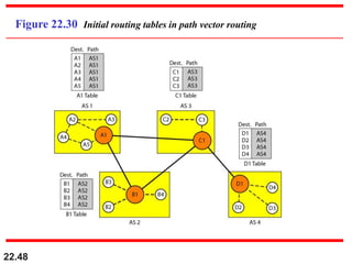
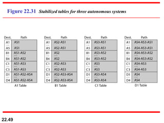
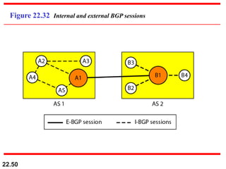
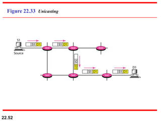
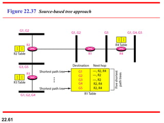
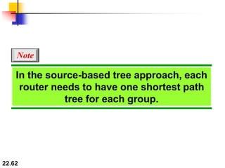
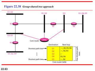
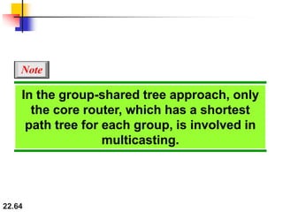
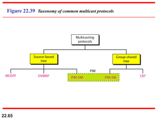
The document summarizes key concepts related to network layer delivery, forwarding, routing, and multicasting. It discusses direct versus indirect delivery and various forwarding techniques like route method versus next-hop method. It also covers unicast routing protocols like distance vector routing (RIP), link state routing (OSPF), and path vector routing (BGP). Finally, it discusses multicasting applications and routing protocols like DVMRP, MOSPF, PIM-SM, and CBT.
2. 22.2
22-1 DELIVERY
The network layer supervises the handling of the
packets by the underlying physical networks. We
define this handling as the delivery of a packet.
Direct Versus Indirect Delivery
Topics discussed in this section:
4. 22.4
22-2 FORWARDING
Forwarding means to place the packet in its route to
its destination. Forwarding requires a host or a router
to have a routing table. When a host has a packet to
send or when a router has received a packet to be
forwarded, it looks at this table to find the route to the
final destination.
Forwarding Techniques
Forwarding Process
Routing Table
Topics discussed in this section:
13. 22.13
Show the forwarding process if a packet arrives at R1 in
Figure 22.6 with the destination address 180.70.65.140.
Example 22.2
Solution
The router performs the following steps:
1. The first mask (/26) is applied to the destination address.
The result is 180.70.65.128, which does not match the
corresponding network address.
2. The second mask (/25) is applied to the destination
address. The result is 180.70.65.128, which matches the
corresponding network address. The next-hop address
and the interface number m0 are passed to ARP for
further processing.
14. 22.14
Show the forwarding process if a packet arrives at R1 in
Figure 22.6 with the destination address 201.4.22.35.
Example 22.3
Solution
The router performs the following steps:
1. The first mask (/26) is applied to the destination
address. The result is 201.4.22.0, which does not
match the corresponding network address.
2. The second mask (/25) is applied to the destination
address. The result is 201.4.22.0, which does not
match the corresponding network address (row 2).
15. 22.15
Example 22.3 (continued)
3. The third mask (/24) is applied to the destination
address. The result is 201.4.22.0, which matches the
corresponding network address. The destination
address of the packet and the interface number m3 are
passed to ARP.
16. 22.16
Show the forwarding process if a packet arrives at R1 in
Figure 22.6 with the destination address 18.24.32.78.
Example 22.4
Solution
This time all masks are applied, one by one, to the
destination address, but no matching network address is
found. When it reaches the end of the table, the module
gives the next-hop address 180.70.65.200 and interface
number m2 to ARP. This is probably an outgoing package
that needs to be sent, via the default router, to someplace
else in the Internet.
19. 22.19
As an example of hierarchical routing, let us consider
Figure 22.9. A regional ISP is granted 16,384 addresses
starting from 120.14.64.0. The regional ISP has decided
to divide this block into four subblocks, each with 4096
addresses. Three of these subblocks are assigned to three
local ISPs; the second subblock is reserved for future use.
Note that the mask for each block is /20 because the
original block with mask /18 is divided into 4 blocks.
Example 22.5
The first local ISP has divided its assigned subblock into
8 smaller blocks and assigned each to a small ISP. Each
small ISP provides services to 128 households, each using
four addresses.
20. 22.20
The second local ISP has divided its block into 4 blocks
and has assigned the addresses to four large
organizations.
Example 22.5 (continued)
There is a sense of hierarchy in this configuration. All
routers in the Internet send a packet with destination
address 120.14.64.0 to 120.14.127.255 to the regional ISP.
The third local ISP has divided its block into 16 blocks
and assigned each block to a small organization. Each
small organization has 256 addresses, and the mask is
/24.
23. 22.23
One utility that can be used to find the contents of a
routing table for a host or router is netstat in UNIX or
LINUX. The next slide shows the list of the contents of a
default server. We have used two options, r and n. The
option r indicates that we are interested in the routing
table, and the option n indicates that we are looking for
numeric addresses. Note that this is a routing table for a
host, not a router. Although we discussed the routing table
for a router throughout the chapter, a host also needs a
routing table.
Example 22.6
24. 22.24
Example 22.6 (continued)
The destination column here defines the network address.
The term gateway used by UNIX is synonymous with
router. This column actually defines the address of the next
hop. The value 0.0.0.0 shows that the delivery is direct. The
last entry has a flag of G, which means that the destination
can be reached through a router (default router). The Iface
defines the interface.
25. 22.25
Example 22.6 (continued)
More information about the IP address and physical
address of the server can be found by using the ifconfig
command on the given interface (eth0).
27. 22.27
22-3 UNICAST ROUTING PROTOCOLS
A routing table can be either static or dynamic. A static
table is one with manual entries. A dynamic table is
one that is updated automatically when there is a
change somewhere in the Internet. A routing protocol
is a combination of rules and procedures that lets
routers in the Internet inform each other of changes.
Optimization
Intra- and Interdomain Routing
Distance Vector Routing and RIP
Link State Routing and OSPF
Path Vector Routing and BGP
Topics discussed in this section:
51. 22.51
22-4 MULTICAST ROUTING PROTOCOLS
In this section, we discuss multicasting and multicast
routing protocols.
Unicast, Multicast, and Broadcast
Applications
Multicast Routing
Routing Protocols
Topics discussed in this section:
72. 22.72
RPB creates a shortest path broadcast
tree from the source to each destination.
It guarantees that each destination
receives one and only one copy
of the packet.
Note
77. 22.77
In CBT, the source sends the multicast
packet (encapsulated in a unicast
packet) to the core router. The core
router decapsulates the packet and
forwards it to all interested interfaces.
Note
79. 22.79
PIM-DM uses RPF and pruning and
grafting strategies to handle
multicasting.
However, it is independent of the
underlying unicast protocol.
Note