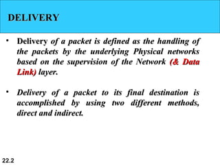
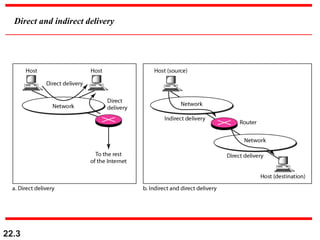
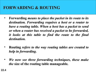
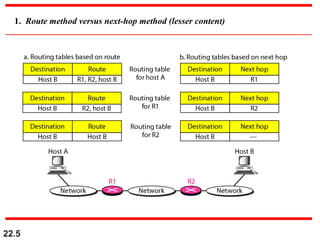
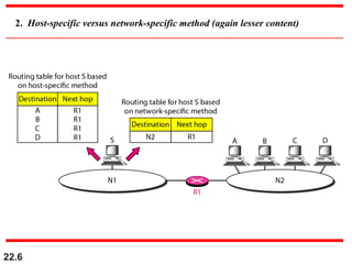
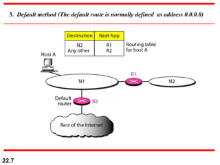
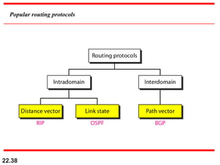
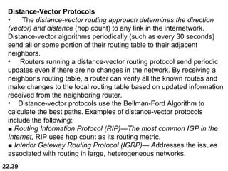
Delivery, Forwarding and Routing
Networking Fundamentals
22.2
DELIVERYDELIVERY
• DeliveryDelivery of a packet is defined as the handling ofof a packet is defined as the handling of
the packets by the underlying Physical networksthe packets by the underlying Physical networks
based on the supervision of the Networkbased on the supervision of the Network (& Data(& Data
Link)Link) layer.layer.
• Delivery of a packet to its final destination isDelivery of a packet to its final destination is
accomplished by using two different methods,accomplished by using two different methods,
direct and indirect.direct and indirect.
22.3
Direct and indirect delivery
22.4
FORWARDING & ROUTINGFORWARDING & ROUTING
• ForwardingForwarding means to place the packet in its route to itsmeans to place the packet in its route to its
destination. Forwarding requires a host or a router todestination. Forwarding requires a host or a router to
have a routing table. When a host has a packet to sendhave a routing table. When a host has a packet to send
or when a router has received a packet to be forwarded,or when a router has received a packet to be forwarded,
it looks at this table to find the route to the finalit looks at this table to find the route to the final
destination.destination.
• RoutingRouting refers to the way routing tables are created torefers to the way routing tables are created to
help in forwarding.help in forwarding.
• We now see three forwarding techniques, these makeWe now see three forwarding techniques, these make
thethe size of the routing table manageablesize of the routing table manageable..
22.5
1. Route method versus next-hop method (lesser content)
22.6
2. Host-specific versus network-specific method (again lesser content)
22.7
3. Default method (The default route is normally defined as address 0.0.0.0)
22.8
Classless Inter-Domain Routing (CIDR) is a system
of IP addressing and routing that solves the many
problems of “classful” addressing by eliminating
fixed address classes in favor of a flexible,
multiple-level, hierarchical structure of networks
of varying size.
Note
22.9
22.10
Simplified forwarding module in classless address
22.11
In classless addressing, we need at
least four columns in a routing table.
Usually there are more.
Note
22.12
Make a routing table for router R1, using the
configuration in Figure.
Example 1
Solution
Table after the figure shows the corresponding table.
22.13
Configuration for Example 1
m3
22.14
Routing table for router R1 in Figure
Actually, for Default route, Mask should be /0 and Network Address
should be 0.0.0.0
22.15
Show the forwarding process if a packet arrives at R1 in
Figure with the destination address 180.70.65.140.
Example 2
Solution
The router performs the following steps:
1. The first mask (/26) is applied to the destination address.
The result is 180.70.65.128, which does not match the
corresponding network address.
2. The second mask (/25) is applied to the destination
address. The result is 180.70.65.128, which matches the
corresponding network address. The desination address
and the interface number m0 are passed to ARP for
further processing.
22.16
Show the forwarding process if a packet arrives at R1 in
Figure with the destination address 201.4.22.35.
Example 3
Solution
The router performs the following steps:
1. The first mask (/26) is applied to the destination
address. The result is 201.4.22.0, which does not
match the corresponding network address.
2. The second mask (/25) is applied to the destination address. The
result is 201.4.22.0, which does not match the corresponding
network address (row 2).
3. The third mask (/24) is applied to the destination
address. The result is 201.4.22.0, which matches the
corresponding network address. The destination
address of the packet and the interface number m3 are
passed to ARP.
22.17
Show the forwarding process if a packet arrives at R1 in
Figure with the destination address 18.24.32.78.
Example 4
Solution
This time all masks are applied, one by one, to the
destination address, but no matching network address is
found. When it reaches the end of the table, the module
gives the next-hop address 180.70.65.200 and interface
number m2 to ARP. This is probably an outgoing
package that needs to be sent, via the default router, to
someplace else in the Internet.
22.18
22.19
Address aggregation
22.20
22.21
Longest mask matching
22.22
Earlier
22.23
As an example of hierarchical routing, let us consider the
Figure. A regional ISP is granted 16,384 addresses
starting from 120.14.64.0. The regional ISP has decided
to divide this block into four subblocks, each with 4096
addresses. Three of these subblocks are assigned to three
local ISPs; the second subblock is reserved for future use.
Note that the mask for each block is /20 because the
original block with mask /18 is divided into 4 blocks.
Example 5
The first local ISP has divided its assigned subblock into
8 smaller blocks and assigned each to a small ISP. Each
small ISP provides services to 128 households, each using
four addresses.
22.24
The second local ISP has divided its block into 4 blocks and has
assigned the addresses to four large organizations.
Example 5 (continued)
There is a sense of hierarchy in this configuration. All routers in
the Internet send a packet with destination address 120.14.64.0 to
120.14.127.255 to the regional ISP.
The regional ISP sends every packet between 120.14.64.0 to
120.14.79.255 to local ISP1.
Local ISP1 sends every packet between 120.14.64.0 to
120.14.65.255 to Small ISP1.
Small ISP1 sends every packet between 120.14.64.0 to 120.14.64.3
to H001.
The third local ISP has divided its block into 16 blocks and
assigned each block to a small organization. Each small
organization has 256 addresses, and the mask is /24.
22.25
Hierarchical routing with ISPs
120.14.127.255
120.14.79.255
120.14.95.255
120.14.111.255
120.14.127.255
8
120.14.65.255
120.14.79.255
120.14.64.3
120.14.99.255
120.14.112.255
22.26
22.27
Common fields in a routing table
22.28
22.29
One utility that can be used to find the contents of a
routing table for a host or router is netstat in UNIX or
LINUX. The next slide shows the list of the contents of a
default server. We have used two options, r and n. The
option r indicates that we are interested in the routing
table, and the option n indicates that we are looking for
numeric addresses. Note that this is a routing table for a
host, not a router. Although we discussed the routing table
for a router throughout, a host also needs a routing table.
Example 6
22.30
Example 6 (continued)
The destination column here defines the network address.
The term gateway used by UNIX is synonymous with
router. This column actually defines the address of the next
hop. The value 0.0.0.0 shows that the delivery is direct. The
last entry has a flag of G, which means that the destination
can be reached through a router (default router). The Iface
defines the interface.
22.31
Example 6 (continued)
More information about the IP address and physical
address of the server can be found by using the ifconfig
command on the given interface (eth0).
22.32
Configuration of the server for Example 6
22.33
Destination : The destination can be an IP network address.
Netmask : Specifies the netmask (also known as a subnet mask)
Gateway : Specifies the forwarding or next hop IP address over which the set of addresses defined by the 
network destination and subnet mask are reachable. 
22.34
22.35
UNICAST ROUTING PROTOCOLSUNICAST ROUTING PROTOCOLS
• A routing table can be eitherA routing table can be either staticstatic oror dynamicdynamic. A. A
static table is one with manual entries. A dynamicstatic table is one with manual entries. A dynamic
table is one that is updated automatically whentable is one that is updated automatically when
there is a change somewhere in the Internet.there is a change somewhere in the Internet.
• A routing protocol is a combination of rules andA routing protocol is a combination of rules and
procedures that lets routers in the Internet informprocedures that lets routers in the Internet inform
each other of changes.each other of changes.
• A dynamic routing table is updated periodically byA dynamic routing table is updated periodically by
using one of these protocols.using one of these protocols.
22.36
col
22.37
Autonomous systems
22.38
Popular routing protocols
22.39
Distance-Vector Protocols
• The distance-vector routing approach determines the direction
(vector) and distance (hop count) to any link in the internetwork.
Distance-vector algorithms periodically (such as every 30 seconds)
send all or some portion of their routing table to their adjacent
neighbors.
• Routers running a distance-vector routing protocol send periodic
updates even if there are no changes in the network. By receiving a
neighbor’s routing table, a router can verify all the known routes and
make changes to the local routing table based on updated information
received from the neighboring router.
• Distance-vector protocols use the Bellman-Ford Algorithm to
calculate the best paths. Examples of distance-vector protocols
include the following:
■ Routing Information Protocol (RIP)—The most common IGP in the
Internet, RIP uses hop count as its routing metric.
■ Interior Gateway Routing Protocol (IGRP)— Addresses the issues
associated with routing in large, heterogeneous networks.
22.40
Link-State Protocols
• Link-state routing protocols were designed to overcome the
limitations of distance vector routing protocols. Link-state routing
protocols respond quickly to network changes, send trigger updates
only when a network change has occurred, and send periodic updates
(called link-state refreshes) at long time intervals, such as every 30
minutes.
• When a link changes state, the device that detected the change
creates a link-state advertisement (LSA) concerning that link (route),
and that LSA is propagated to all neighboring devices. Each routing
device takes a copy of the LSA, updates its link-state (topological)
database, and forwards the LSA to all neighboring devices. This
flooding of the LSA is required to ensure that all routing devices
update their databases before creating an updated routing table that
reflects the new topology.
• The link-state database is used to calculate the best paths
through the network by applying the Dijkstra Shortest Path First (SPF)
algorithm
• Examples of link-state protocols are OSPF and IS-IS.
22.41
BGP
• Border Gateway Protocol (BGP) is an example of an
EGP. BGP exchanges routing information between
autonomous systems while guaranteeing loop-free path
selection.
• It is the principal route advertising protocol used by
major companies and ISPs on the Internet. BGP-4 is the
first version of BGP that supports classless interdomain
routing (CIDR) and route aggregation.
• Unlike common IGPs such as RIP, OSPF, and
EIGRP, BGP does not use metrics such as hop count or
bandwidth or delay.
• Instead, BGP makes routing decisions based on
network policies or rules using various BGP path
attributes.

4d routing

  • 1.
    Delivery, Forwarding andRouting Networking Fundamentals
  • 2.
    22.2 DELIVERYDELIVERY • DeliveryDelivery ofa packet is defined as the handling ofof a packet is defined as the handling of the packets by the underlying Physical networksthe packets by the underlying Physical networks based on the supervision of the Networkbased on the supervision of the Network (& Data(& Data Link)Link) layer.layer. • Delivery of a packet to its final destination isDelivery of a packet to its final destination is accomplished by using two different methods,accomplished by using two different methods, direct and indirect.direct and indirect.
  • 3.
  • 4.
    22.4 FORWARDING & ROUTINGFORWARDING& ROUTING • ForwardingForwarding means to place the packet in its route to itsmeans to place the packet in its route to its destination. Forwarding requires a host or a router todestination. Forwarding requires a host or a router to have a routing table. When a host has a packet to sendhave a routing table. When a host has a packet to send or when a router has received a packet to be forwarded,or when a router has received a packet to be forwarded, it looks at this table to find the route to the finalit looks at this table to find the route to the final destination.destination. • RoutingRouting refers to the way routing tables are created torefers to the way routing tables are created to help in forwarding.help in forwarding. • We now see three forwarding techniques, these makeWe now see three forwarding techniques, these make thethe size of the routing table manageablesize of the routing table manageable..
  • 5.
    22.5 1. Route methodversus next-hop method (lesser content)
  • 6.
    22.6 2. Host-specific versusnetwork-specific method (again lesser content)
  • 7.
    22.7 3. Default method(The default route is normally defined as address 0.0.0.0)
  • 8.
    22.8 Classless Inter-Domain Routing(CIDR) is a system of IP addressing and routing that solves the many problems of “classful” addressing by eliminating fixed address classes in favor of a flexible, multiple-level, hierarchical structure of networks of varying size. Note
  • 9.
  • 10.
  • 11.
    22.11 In classless addressing,we need at least four columns in a routing table. Usually there are more. Note
  • 12.
    22.12 Make a routingtable for router R1, using the configuration in Figure. Example 1 Solution Table after the figure shows the corresponding table.
  • 13.
  • 14.
    22.14 Routing table forrouter R1 in Figure Actually, for Default route, Mask should be /0 and Network Address should be 0.0.0.0
  • 15.
    22.15 Show the forwardingprocess if a packet arrives at R1 in Figure with the destination address 180.70.65.140. Example 2 Solution The router performs the following steps: 1. The first mask (/26) is applied to the destination address. The result is 180.70.65.128, which does not match the corresponding network address. 2. The second mask (/25) is applied to the destination address. The result is 180.70.65.128, which matches the corresponding network address. The desination address and the interface number m0 are passed to ARP for further processing.
  • 16.
    22.16 Show the forwardingprocess if a packet arrives at R1 in Figure with the destination address 201.4.22.35. Example 3 Solution The router performs the following steps: 1. The first mask (/26) is applied to the destination address. The result is 201.4.22.0, which does not match the corresponding network address. 2. The second mask (/25) is applied to the destination address. The result is 201.4.22.0, which does not match the corresponding network address (row 2). 3. The third mask (/24) is applied to the destination address. The result is 201.4.22.0, which matches the corresponding network address. The destination address of the packet and the interface number m3 are passed to ARP.
  • 17.
    22.17 Show the forwardingprocess if a packet arrives at R1 in Figure with the destination address 18.24.32.78. Example 4 Solution This time all masks are applied, one by one, to the destination address, but no matching network address is found. When it reaches the end of the table, the module gives the next-hop address 180.70.65.200 and interface number m2 to ARP. This is probably an outgoing package that needs to be sent, via the default router, to someplace else in the Internet.
  • 18.
  • 19.
  • 20.
  • 21.
  • 22.
  • 23.
    22.23 As an exampleof hierarchical routing, let us consider the Figure. A regional ISP is granted 16,384 addresses starting from 120.14.64.0. The regional ISP has decided to divide this block into four subblocks, each with 4096 addresses. Three of these subblocks are assigned to three local ISPs; the second subblock is reserved for future use. Note that the mask for each block is /20 because the original block with mask /18 is divided into 4 blocks. Example 5 The first local ISP has divided its assigned subblock into 8 smaller blocks and assigned each to a small ISP. Each small ISP provides services to 128 households, each using four addresses.
  • 24.
    22.24 The second localISP has divided its block into 4 blocks and has assigned the addresses to four large organizations. Example 5 (continued) There is a sense of hierarchy in this configuration. All routers in the Internet send a packet with destination address 120.14.64.0 to 120.14.127.255 to the regional ISP. The regional ISP sends every packet between 120.14.64.0 to 120.14.79.255 to local ISP1. Local ISP1 sends every packet between 120.14.64.0 to 120.14.65.255 to Small ISP1. Small ISP1 sends every packet between 120.14.64.0 to 120.14.64.3 to H001. The third local ISP has divided its block into 16 blocks and assigned each block to a small organization. Each small organization has 256 addresses, and the mask is /24.
  • 25.
    22.25 Hierarchical routing withISPs 120.14.127.255 120.14.79.255 120.14.95.255 120.14.111.255 120.14.127.255 8 120.14.65.255 120.14.79.255 120.14.64.3 120.14.99.255 120.14.112.255
  • 26.
  • 27.
    22.27 Common fields ina routing table
  • 28.
  • 29.
    22.29 One utility thatcan be used to find the contents of a routing table for a host or router is netstat in UNIX or LINUX. The next slide shows the list of the contents of a default server. We have used two options, r and n. The option r indicates that we are interested in the routing table, and the option n indicates that we are looking for numeric addresses. Note that this is a routing table for a host, not a router. Although we discussed the routing table for a router throughout, a host also needs a routing table. Example 6
  • 30.
    22.30 Example 6 (continued) Thedestination column here defines the network address. The term gateway used by UNIX is synonymous with router. This column actually defines the address of the next hop. The value 0.0.0.0 shows that the delivery is direct. The last entry has a flag of G, which means that the destination can be reached through a router (default router). The Iface defines the interface.
  • 31.
    22.31 Example 6 (continued) Moreinformation about the IP address and physical address of the server can be found by using the ifconfig command on the given interface (eth0).
  • 32.
    22.32 Configuration of theserver for Example 6
  • 33.
  • 34.
  • 35.
    22.35 UNICAST ROUTING PROTOCOLSUNICASTROUTING PROTOCOLS • A routing table can be eitherA routing table can be either staticstatic oror dynamicdynamic. A. A static table is one with manual entries. A dynamicstatic table is one with manual entries. A dynamic table is one that is updated automatically whentable is one that is updated automatically when there is a change somewhere in the Internet.there is a change somewhere in the Internet. • A routing protocol is a combination of rules andA routing protocol is a combination of rules and procedures that lets routers in the Internet informprocedures that lets routers in the Internet inform each other of changes.each other of changes. • A dynamic routing table is updated periodically byA dynamic routing table is updated periodically by using one of these protocols.using one of these protocols.
  • 36.
  • 37.
  • 38.
  • 39.
    22.39 Distance-Vector Protocols • Thedistance-vector routing approach determines the direction (vector) and distance (hop count) to any link in the internetwork. Distance-vector algorithms periodically (such as every 30 seconds) send all or some portion of their routing table to their adjacent neighbors. • Routers running a distance-vector routing protocol send periodic updates even if there are no changes in the network. By receiving a neighbor’s routing table, a router can verify all the known routes and make changes to the local routing table based on updated information received from the neighboring router. • Distance-vector protocols use the Bellman-Ford Algorithm to calculate the best paths. Examples of distance-vector protocols include the following: ■ Routing Information Protocol (RIP)—The most common IGP in the Internet, RIP uses hop count as its routing metric. ■ Interior Gateway Routing Protocol (IGRP)— Addresses the issues associated with routing in large, heterogeneous networks.
  • 40.
    22.40 Link-State Protocols • Link-staterouting protocols were designed to overcome the limitations of distance vector routing protocols. Link-state routing protocols respond quickly to network changes, send trigger updates only when a network change has occurred, and send periodic updates (called link-state refreshes) at long time intervals, such as every 30 minutes. • When a link changes state, the device that detected the change creates a link-state advertisement (LSA) concerning that link (route), and that LSA is propagated to all neighboring devices. Each routing device takes a copy of the LSA, updates its link-state (topological) database, and forwards the LSA to all neighboring devices. This flooding of the LSA is required to ensure that all routing devices update their databases before creating an updated routing table that reflects the new topology. • The link-state database is used to calculate the best paths through the network by applying the Dijkstra Shortest Path First (SPF) algorithm • Examples of link-state protocols are OSPF and IS-IS.
  • 41.
    22.41 BGP • Border GatewayProtocol (BGP) is an example of an EGP. BGP exchanges routing information between autonomous systems while guaranteeing loop-free path selection. • It is the principal route advertising protocol used by major companies and ISPs on the Internet. BGP-4 is the first version of BGP that supports classless interdomain routing (CIDR) and route aggregation. • Unlike common IGPs such as RIP, OSPF, and EIGRP, BGP does not use metrics such as hop count or bandwidth or delay. • Instead, BGP makes routing decisions based on network policies or rules using various BGP path attributes.