Download to read offline

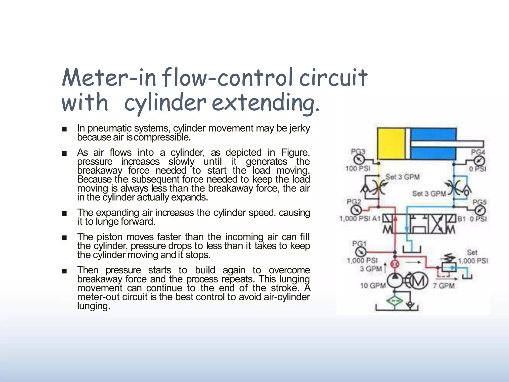
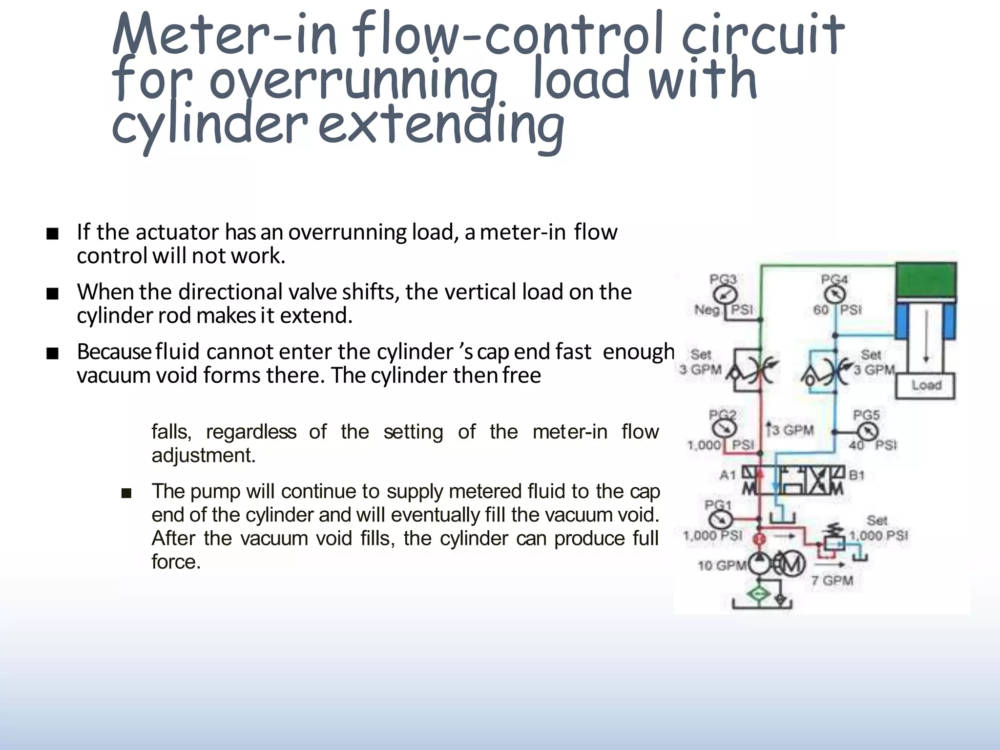


This document discusses meter-in flow-control circuits. It explains that meter-in circuits allow fluid to enter an actuator, like a cylinder, at a controlled rate to provide smooth movement. However, meter-in circuits may not work for overrunning loads, as a vacuum can form and cause the cylinder to free fall until filled. The document provides diagrams of meter-in circuits and explains how they regulate cylinder speed by metering fluid into the blind end.


