Downloaded 3,013 times
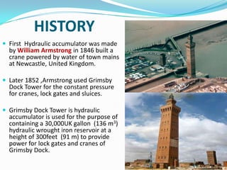
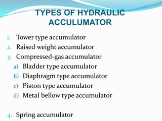
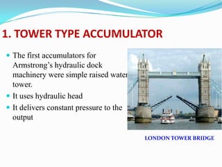
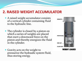
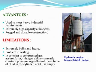

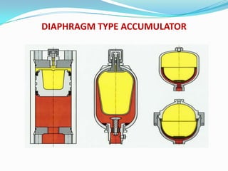
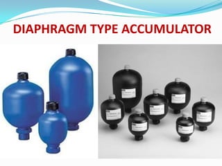
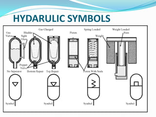
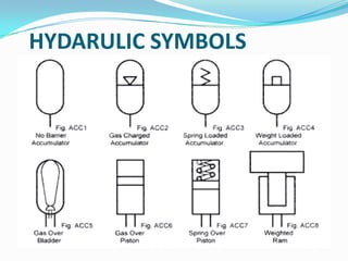
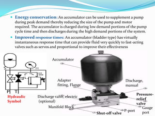
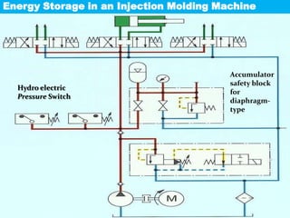
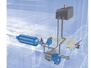
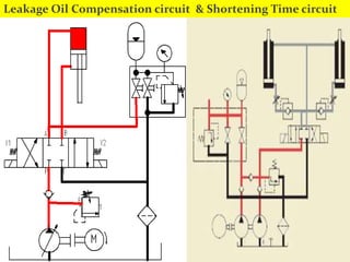
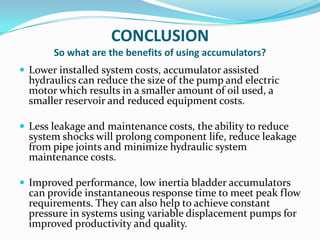

The document provides a comprehensive overview of hydraulic accumulators, including their history, types, functions, and design considerations. It explains various types of accumulators (e.g., tower, compressed gas, diaphragm) and their applications, such as energy storage, shock absorption, and leakage compensation. Additionally, it highlights the benefits of using accumulators, including reduced costs, improved performance, and lower noise levels.


![Introduction-to-Hydraulic-Accumulatorssss (1)[1] 1 (2).pptx](https://cdn.slidesharecdn.com/ss_thumbnails/introduction-to-hydraulic-accumulatorssss1112-251217204059-16265c2e-thumbnail.jpg?width=640&height=640&fit=bounds)


