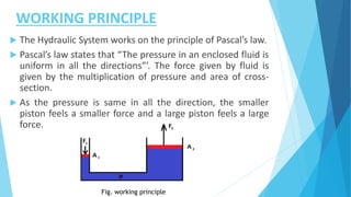
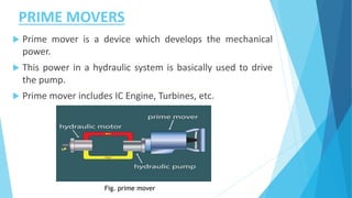
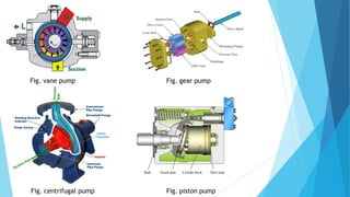
the ladakh protest in leh ladakh 2024 sonam wangchuk.pptx
Hydraulic control system
1. HYDRAULIC CONTROL SYSTEM
PRESENTED BY :-
CHAUDHARY KALPESH (180613119003)
MALI DHAVAL .R. (180613119006)
PRAJAPATI MEHUL .S. (180613119011)
SHAH PRIYANK .P. (180613119014)
THAKOR MITESH .R. (180613119016)
GUIDED BY :-
PROF. A.R.CHAUDHARY
2. CONTENT
ABSTRACT
INTRODUCTION
WORKING PRINCIPLE
SCHEMATIC DIAGRAM OF HYDRAULIC SYSTEM
COMPONENTS OF HYDRAULIC SYSTEM
APPLICATIONS OF HYDRAULIC CONTROL SYSTEM
3. ABSTRACT
Hydraulic control system of butterfly valves are presently
valve-controlled and pump-controlled. Valve-controlled
hydraulic systems have serious power loss and generate
much heat during throttling. Pump- controlled hydraulic
systems have no overflow or throttling losses but are limited
in the speed adjustment of the variable-displacement pump,
generate much noise, pollute the environment, and have
motor power that does not match load requirement,
resulting in low efficiency under light loads and wearing of
the variable-displacement pump. the system is compact,
produces a large output force, provide stable transmission.
4. INTRODUCTION
The controlled movement of parts or a controlled
application of force is a common requirement in the
industries.
These operations are performed mainly by using electrical
machines or diesel, petrol and steam engines as a prime
mover.
The enclosed fluids (liquids and gases) can also be used as
prime movers to provide controlled motion and force to
the objects or substances.
The specially designed enclosed fluid systems can provide
both linear as well as rotary motion.
5. WORKING PRINCIPLE
The Hydraulic System works on the principle of Pascal’s law.
Pascal’s law states that “The pressure in an enclosed fluid is
uniform in all the directions”’. The force given by fluid is
given by the multiplication of pressure and area of cross-
section.
As the pressure is same in all the direction, the smaller
piston feels a smaller force and a large piston feels a large
force.
Fig. working principle
7. COMPONENTS OF HYDRAULIC SYSTEM
The major components of a hydraulic system are:
Prime Mover
Pump
Control Valves
Actuators(Hydraulic motors, pistons)
Fluid
Filters
Protective Devices
Control Devices
8. PRIME MOVERS
Prime mover is a device which develops the mechanical
power.
This power in a hydraulic system is basically used to drive
the pump.
Prime mover includes IC Engine, Turbines, etc.
Fig. prime mover
9. HYDRAULIC PUMP
Pump is a device which converts mechanical energy to
fluid energy.
The hydraulic pump takes hydraulic fluid (mostly some
oil) from the storage tank and delivers it to the rest of
the hydraulic circuit.
The hydraulic pumps are characterized by its flow rate
capacity, power consumption, drive speed, pressure
delivered at the outlet and efficiency of the pump.
EX. Vane pump, piston pump, Gear pump, Centrifugal
pump,
11. CONTROL VALVES
The control of the mechanical outputs (motion and force)
is one of the most important functions in a hydraulic
system.
The proper selection of control selection ensures the
desired output and safe function of the system.
In order to control the hydraulic outputs, different types of
control valves are required.
There are basically three types of valves employed in
hydraulic systems:
1. Directional control valves
2. Flow control valves
3. Pressure control valves
14. 3. PRESSURE CONTROL VALVE
The pressure control valves
are used to protect the
hydraulic components from
excessive pressure.
It is normally a closed type
and it when the pressure
exceeds a maximum value
by diverting pump flow back
to the tank.
Pressure control valves are
the functional part of the
system
Fig. pressure control valve
15. HYDRAULIC ACTUATORS
Hydraulic Actuators employ hydraulic pressure to drive an
output member.
These are used where high speed and large forces are
required.
The fluid used in hydraulic actuator is highly incompressible.
They convert fluid power into mechanical power.
Depending on motion they can be classified as:
1. Linear actuators: linear motion as output(cylinder
and piston) .
2. Rotary actuator: rotary motion as output(motor).
17. 2. HYDRAULIC MOTORS
Motors work exactly on the reverse
principle of pumps.
Output Shaft
In motors fluid is forced into the
motor from pump outlets at high
pressure and is converted to
mechanical energy.
This fluid pressure creates the motion
of the motor shaft.
EX. Vane motors, gear motors.
Fig. Hydraulic motor
18. HYDRAULIC FLUID
Hydraulic fluid must be essentially non-compressible to be
able to transmit power instantaneously from one part of
the system to another.
The most common liquid used in hydraulic systems is
petroleum oil because it is only very slightly compressible.
Properties of hydraulic fluids:
Non compressible Fire resistance
Low toxicity Good lubricator
Low volatility Corrosion control
19. FILTERS
The hydraulic fluid is kept clean in
the system with the help of filters
and strainers.
It removes minute particles from the
fluid, which can cause blocking of
the orifices of servo-valves or cause
jamming of spools.
EX. Suction filters, pressure side
filters, return side filters, offline
filters. Fig. Filter
20. APPLICATIONS OF HYDRAULIC
SYSTEMS
Industrial: Plastic processing machineries, steel making
and primary metal extraction applications, automated
production lines, etc.
Mobile hydraulics: Tractors, irrigation system, earthmoving
equipment, material handling equipment etc.
Automobiles: It is used in the systems like breaks, shock
absorbers, steering system, lift and cleaning etc.
Marine applications: It mostly covers ocean going vessels,
fishing boats and navel equipment.
Aerospace equipment: There are equipment and systems
used for rudder control, landing gear, breaks etc.