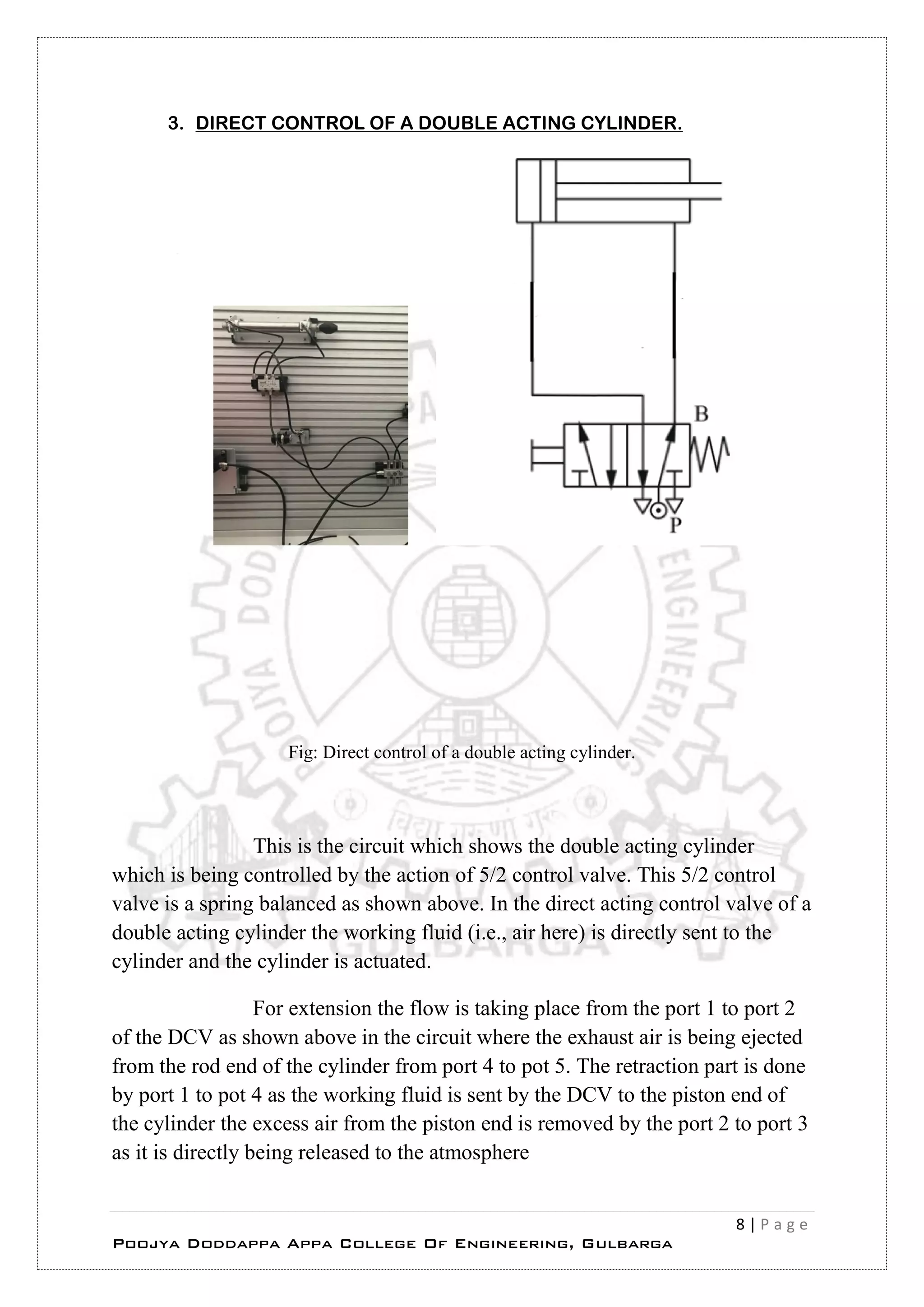
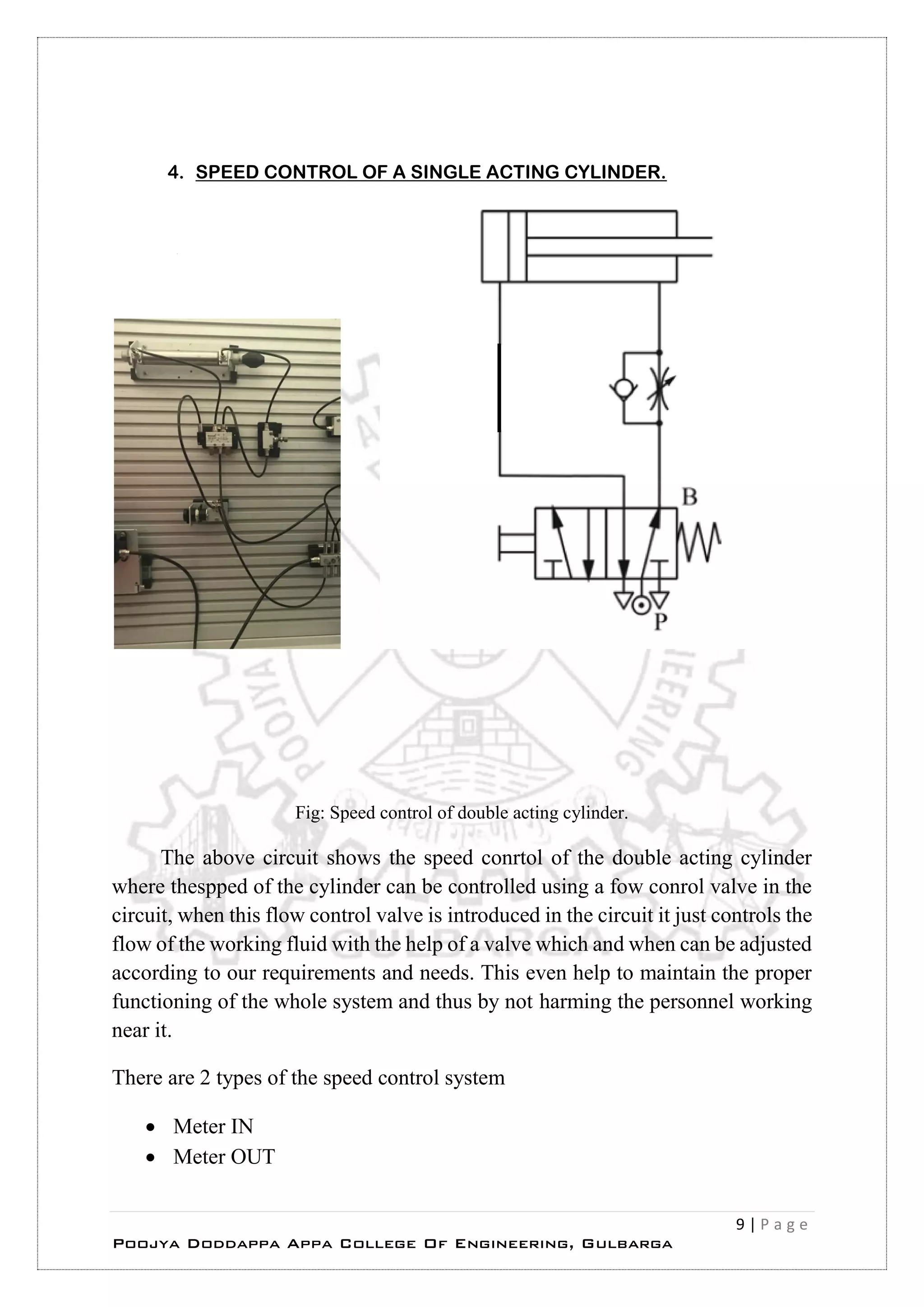
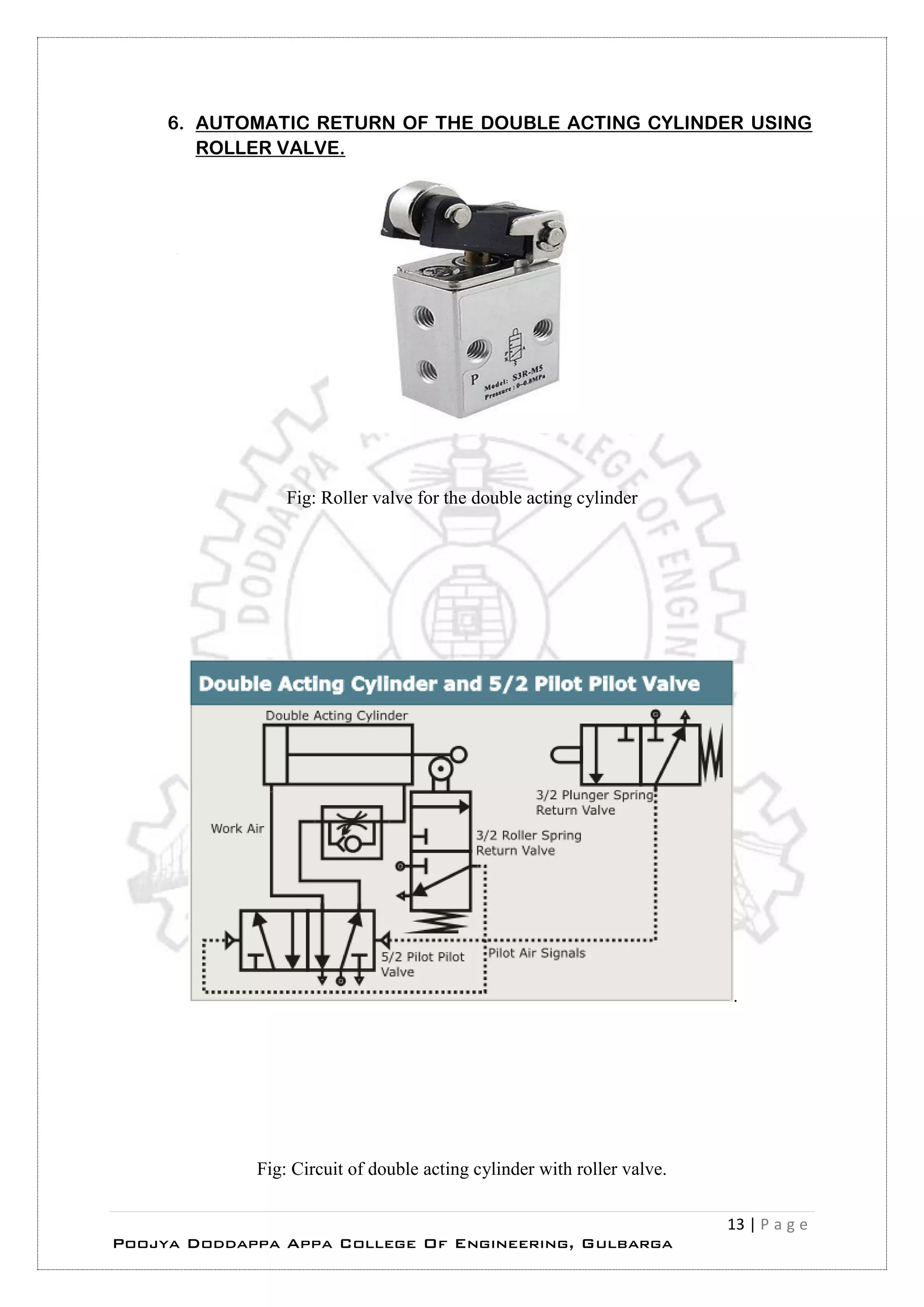
SlideShare a Scribd company logo
1 of 14
HYDRAULIC AND
PNEUMATIC EXPERIMENTS
– A REPORT
CONDUCTED AT BOSCH HYDRAULIC AND PNEUMATIC
CENTRE
GULBARGA
DEPARTMENT OF MECHANICAL ENGINEERING
SUBMITTED ON
5/6/2017
Submitted by,
Vidyasagar Ghantoji
6th sem ‘A’ section
Roll No. 06
Vtu no. : 3PD13ME093
THIS IS THE BRIEF REPORT ON THE EXPERIMENTS THAT ARE CARRIED OUT AT THE HYDRAULICS
AND PNEUMATICS LABROTARY OF BOSCH CENTRE KALABURAGI. THE EXPERIMENTS LEARNT ARE
BRIEFED HERE IN THIS REPORT.
2 | P a g e
Poojya Doddappa Appa College Of Engineering, Gulbarga
INDEX
TOPIC Page
no.
Remarks
 Structure of a pnematic system 4
 Direct control of a single acting cylinder 5
 Indirect control of a single acting cylinder 6
 Direct control of a double acting cylinder 8
 Speed control of a single acting cylinder 9
 Quick exhaust valve 11
 Circuit using a Roller Valve 13
3 | P a g e
Poojya Doddappa Appa College Of Engineering, Gulbarga
Acknowledgement
I would like to express my gratitude in completing this report and performing the
experiments successfully and the efforts in teaching by my beloved lecturer Mr.
R. M. Latthe
Prof. R. M. Latthe has been a very great inspiration under whose guidance I have
been able to learn and understand and complete the experiments in the
BOSCH- REXROTH laboratory which is one of its kind in this North Karnataka.
Without his perseverance we wouldn’t have had any hands on experience of
handling and learning on this machines and circuits.
Because of the efforts of Prof. R. M. Latthe students of this area will be benefitted
All along prof. R.M. Latthe has been with me in successfully completing
He is definitely one of his kind!
4 | P a g e
Poojya Doddappa Appa College Of Engineering, Gulbarga
The above flow chart shows the structure of a pneumatic system
5 | P a g e
Poojya Doddappa Appa College Of Engineering, Gulbarga
1. DIRECT CONTROL OF A SINGLE ACTING CYLINDER.
Fig: Direct control of single acting cylinder.
This is the circuit in the figure which shows the direct control of a single acting
cylinder which is used to control the actuator using the 3/2 DCV which is a spring
retracted valve and even has a push button. Where the working fluid ( i.e. air over
here) is sent directly to the single acting cylinder and the actuator moves.
Here for the extension the flow of the working fluid is done from 1 to 2 port of
the DCV, for retraction the port 2 is directly connected to the exhaust port
6 | P a g e
Poojya Doddappa Appa College Of Engineering, Gulbarga
2. INDIRECT CONTROL OF A SINGLE ACTING CYLINDER.
Fig:Indirect control of single acting cylinder
7 | P a g e
Poojya Doddappa Appa College Of Engineering, Gulbarga
This is the circuit which shows that a cylinder is being controlled by a 3/2
DCV where there is a push button and a spring retracted type and the other is
operated using piolet and spring operated type. As the name suggests this is the
indirect acting single acting control system where the working fluid (i.e., air here)
is sent to the cylinder or the actuator indirectly via the push button and the DCV
and hence the work is completed
Generally, in the industrial applications the indirect type of single acting
cylinder is preferred so as to maintain the safety precaution aspects as the pressure
in the industrial applications exceed to 6 bar. For extension the flow of the air is
from 1 to 2 ports of the DCV which is being operated using push button for which
it sends the signal to the DCV to get the extension of the actuator. For the
retraction process the port 2 of the DCV which is piolet operated is directly
connected to the exhaust port and hence the work is safely done.
8 | P a g e
Poojya Doddappa Appa College Of Engineering, Gulbarga
3. DIRECT CONTROL OF A DOUBLE ACTING CYLINDER.
Fig: Direct control of a double acting cylinder.
This is the circuit which shows the double acting cylinder
which is being controlled by the action of 5/2 control valve. This 5/2 control
valve is a spring balanced as shown above. In the direct acting control valve of a
double acting cylinder the working fluid (i.e., air here) is directly sent to the
cylinder and the cylinder is actuated.
For extension the flow is taking place from the port 1 to port 2
of the DCV as shown above in the circuit where the exhaust air is being ejected
from the rod end of the cylinder from port 4 to pot 5. The retraction part is done
by port 1 to pot 4 as the working fluid is sent by the DCV to the piston end of
the cylinder the excess air from the piston end is removed by the port 2 to port 3
as it is directly being released to the atmosphere
9 | P a g e
Poojya Doddappa Appa College Of Engineering, Gulbarga
4. SPEED CONTROL OF A SINGLE ACTING CYLINDER.
Fig: Speed control of double acting cylinder.
The above circuit shows the speed conrtol of the double acting cylinder
where thespped of the cylinder can be controlled using a fow conrol valve in the
circuit, when this flow control valve is introduced in the circuit it just controls the
flow of the working fluid with the help of a valve which and when can be adjusted
according to our requirements and needs. This even help to maintain the proper
functioning of the whole system and thus by not harming the personnel working
near it.
There are 2 types of the speed control system
 Meter IN
 Meter OUT
10 | P a g e
Poojya Doddappa Appa College Of Engineering, Gulbarga
The above circuit shows a Meter OUT system where in the
cyclinder is maintained at the definite movement of the cylinder. For the
extension of the cylinder the flow of the working fluid is taking place from the
port 1 to port 2 of the Direction control valve and the excess air present is removed
from the rod end of the actuator/ cylinder.
The double acting cylinder is controlled by the action of one 5/2
valve which is spring balanced and push button operated as shown in the figure.
This is the speed control of the double acting cylinder where the speed of the
cylinder is to be maintained for the proper functioning of the system to do a
particular work.For extension the flow of the working fluid is from port 1 to port
2 of the DCV and the extension of the actuator takes place thus by ejecting the
air present in the rod end of the cylinder from ports 4 and 5, the air which is
ejected will be passing through the check valve and the throttle valve and then
flow to the orifice which can control the speed of the air thus by controlling the
speed of the cylinder too. Hence for the retraction of the cylinder the flow of the
working fluid is from the ports 1 to 4 and the flow is directly from the ports which
doesn’t turn up with the orifice and hence the piston is moved from the position
2 to 3 and the excess air from the rod end of the cylinder is exhausted from the
outlet to the atmosphere.
11 | P a g e
Poojya Doddappa Appa College Of Engineering, Gulbarga
5. USE OF QUICK EXHAUST VALVE TO THE SYSTEM (ANY).
Fig: Quick exhaut valve single cylinder (left) double cylinder circuit (right)
The above type of circuit shows the usage of the quick exhaust
valve where in the valve is fixed at the exhaust side of the woking fluid ( i.e., air
here) the quick return motion of the cylinder shall get some productive time so as
to contuine the next cycle of the work. The quick exhaust vlave is designed in
such a way that the cross section area is greater than the normal exhaust valve so
as to expel out much amount of the working fluid from the cylinder to continue
the work this valve allows the exhaust air directly to the atmosphere with a certain
amount of greater force than that of the normal exhaust valves.
12 | P a g e
Poojya Doddappa Appa College Of Engineering, Gulbarga
The main component of quick exhaust valve is a silencer which
tends to reduce lot much amount if noise created while the working fluid is
expelled but however, there is a ‘Pop’ sound which is caused while the expelling
of the fluid which is not inevitable but a silencer reduces the noise for a greater
extent. The below photo shows a quick exhaust valve with a silencer
Fig: Quick exhaut valve with silencer.
Fig: A Muffler / Silencer
The above photo shows a muffler / silencer which reduces the noise of the air which comes
out to a greater extent. This is a brass type of adustable muffler/ silencer.
13 | P a g e
Poojya Doddappa Appa College Of Engineering, Gulbarga
6. AUTOMATIC RETURN OF THE DOUBLE ACTING CYLINDER USING
ROLLER VALVE.
Fig: Roller valve for the double acting cylinder
.
Fig: Circuit of double acting cylinder with roller valve.
14 | P a g e
Poojya Doddappa Appa College Of Engineering, Gulbarga
The above circuit shows the system which uses the roller valve in
series connected in the path of the cylinder. As the cylinder end touches the roller
the roller at once send the signal to the piolet operated DCV and hence the
retraction takes place at once. This type of valve is very helpful in setting up the
distance of the cylinder and confine that distance to a certain extent. This doesn’t
need any of the switch nor push button to retract due to the presence of the roller
valve.
This type of element is connected so as to adjust the distance to be
travlled by the piston from the cylinder in the circuit.
Figure shows the complete view of the roller valve used in the circuit.

More Related Content

What's hot

2 c industrial hydraulic circuits
2 c industrial hydraulic circuits2 c industrial hydraulic circuits
2 c industrial hydraulic circuitsDr.R. SELVAM
 
Chapter 3 electro pneumatic.updated
Chapter 3 electro pneumatic.updatedChapter 3 electro pneumatic.updated
Chapter 3 electro pneumatic.updatedHattori Sidek
 
Classification of Pneumatic Elements Included Valves, Compressor
Classification of Pneumatic Elements Included Valves, CompressorClassification of Pneumatic Elements Included Valves, Compressor
Classification of Pneumatic Elements Included Valves, CompressorMohammad Azam Khan
 
hydraulic and pneumatic Valves
hydraulic and pneumatic Valveshydraulic and pneumatic Valves
hydraulic and pneumatic ValvesSam Aero
 
2 b industrial hydraulic circuits
2 b industrial hydraulic circuits2 b industrial hydraulic circuits
2 b industrial hydraulic circuitsDr.R. SELVAM
 
2 a industrial hydraulic circuits
2 a industrial hydraulic circuits2 a industrial hydraulic circuits
2 a industrial hydraulic circuitsDr.R. SELVAM
 
Components of hydraulic & pneumetic
Components of hydraulic & pneumeticComponents of hydraulic & pneumetic
Components of hydraulic & pneumeticShivji Dangar
 
Presentation on pneumatic actuator
Presentation on pneumatic actuatorPresentation on pneumatic actuator
Presentation on pneumatic actuatorManish Tiwari
 
Hydraulic Valves and Hydraulic System Accessories
Hydraulic Valves and Hydraulic System AccessoriesHydraulic Valves and Hydraulic System Accessories
Hydraulic Valves and Hydraulic System AccessoriesRAHUL THAKER
 
Hydraulic Valves (Valves) (Pneumatics also)
Hydraulic Valves (Valves) (Pneumatics also)Hydraulic Valves (Valves) (Pneumatics also)
Hydraulic Valves (Valves) (Pneumatics also)Mohammad Azam Khan
 
Pneumatic Control System & ITS Components
Pneumatic Control System & ITS ComponentsPneumatic Control System & ITS Components
Pneumatic Control System & ITS ComponentsUrvesh Prajapati
 
Project Report - Spring 2014
Project Report - Spring 2014Project Report - Spring 2014
Project Report - Spring 2014Garret Stec
 
017 pressure regulation and control valves
017 pressure regulation and control valves017 pressure regulation and control valves
017 pressure regulation and control valvesRob Holt
 
Preliminaries of Pneumatics (Basic Components Details)
Preliminaries of Pneumatics (Basic Components Details)Preliminaries of Pneumatics (Basic Components Details)
Preliminaries of Pneumatics (Basic Components Details)S K
 

What's hot (19)

2 c industrial hydraulic circuits
2 c industrial hydraulic circuits2 c industrial hydraulic circuits
2 c industrial hydraulic circuits
 
Chapter 3 electro pneumatic.updated
Chapter 3 electro pneumatic.updatedChapter 3 electro pneumatic.updated
Chapter 3 electro pneumatic.updated
 
NFI - Industrial Pneumatics
NFI - Industrial PneumaticsNFI - Industrial Pneumatics
NFI - Industrial Pneumatics
 
Classification of Pneumatic Elements Included Valves, Compressor
Classification of Pneumatic Elements Included Valves, CompressorClassification of Pneumatic Elements Included Valves, Compressor
Classification of Pneumatic Elements Included Valves, Compressor
 
hydraulic and pneumatic Valves
hydraulic and pneumatic Valveshydraulic and pneumatic Valves
hydraulic and pneumatic Valves
 
2 b industrial hydraulic circuits
2 b industrial hydraulic circuits2 b industrial hydraulic circuits
2 b industrial hydraulic circuits
 
2 a industrial hydraulic circuits
2 a industrial hydraulic circuits2 a industrial hydraulic circuits
2 a industrial hydraulic circuits
 
Components of hydraulic & pneumetic
Components of hydraulic & pneumeticComponents of hydraulic & pneumetic
Components of hydraulic & pneumetic
 
Pneumatic system
Pneumatic systemPneumatic system
Pneumatic system
 
Presentation on pneumatic actuator
Presentation on pneumatic actuatorPresentation on pneumatic actuator
Presentation on pneumatic actuator
 
Hydraulic Valves and Hydraulic System Accessories
Hydraulic Valves and Hydraulic System AccessoriesHydraulic Valves and Hydraulic System Accessories
Hydraulic Valves and Hydraulic System Accessories
 
Hydraulic Valves (Valves) (Pneumatics also)
Hydraulic Valves (Valves) (Pneumatics also)Hydraulic Valves (Valves) (Pneumatics also)
Hydraulic Valves (Valves) (Pneumatics also)
 
Control valves
Control valvesControl valves
Control valves
 
Pneumatic Control System & ITS Components
Pneumatic Control System & ITS ComponentsPneumatic Control System & ITS Components
Pneumatic Control System & ITS Components
 
Project Report - Spring 2014
Project Report - Spring 2014Project Report - Spring 2014
Project Report - Spring 2014
 
Industrial hydraulics
Industrial hydraulicsIndustrial hydraulics
Industrial hydraulics
 
Pneumatic Power
Pneumatic PowerPneumatic Power
Pneumatic Power
 
017 pressure regulation and control valves
017 pressure regulation and control valves017 pressure regulation and control valves
017 pressure regulation and control valves
 
Preliminaries of Pneumatics (Basic Components Details)
Preliminaries of Pneumatics (Basic Components Details)Preliminaries of Pneumatics (Basic Components Details)
Preliminaries of Pneumatics (Basic Components Details)
 

Similar to Hydraulics And Pneumamatics Experiments.

Control Valves .pdf
Control Valves .pdfControl Valves .pdf
Control Valves .pdfmarcos849547
 
What is a control valve?
What is a control valve?What is a control valve?
What is a control valve?Hossam Moghrabi
 
A Review Paper on Pneumatic Operated Collapsable Steering System
A Review Paper on Pneumatic Operated Collapsable Steering SystemA Review Paper on Pneumatic Operated Collapsable Steering System
A Review Paper on Pneumatic Operated Collapsable Steering SystemIRJET Journal
 
Lab pactice on pneumatic control systems
Lab pactice on pneumatic control systemsLab pactice on pneumatic control systems
Lab pactice on pneumatic control systemsEphremZemedkun
 
3 valve shafts pneumatics and hydraulics
3 valve shafts pneumatics and hydraulics3 valve shafts pneumatics and hydraulics
3 valve shafts pneumatics and hydraulicsaman520305
 
Ii air control valves
Ii air control valvesIi air control valves
Ii air control valvesmoroyusef
 
Various Mechanical Units Involved in The Bottling Of LPG cylinders
Various Mechanical Units Involved in The Bottling Of LPG cylindersVarious Mechanical Units Involved in The Bottling Of LPG cylinders
Various Mechanical Units Involved in The Bottling Of LPG cylindersMohit Dhull
 
EMERGENCY BRAKING SYSTEM.pptx
EMERGENCY BRAKING SYSTEM.pptxEMERGENCY BRAKING SYSTEM.pptx
EMERGENCY BRAKING SYSTEM.pptxGokul740367
 
Basic pneumatics
Basic pneumaticsBasic pneumatics
Basic pneumaticsRutwikBonde
 
Instrumentation positioner presentation
Instrumentation positioner presentationInstrumentation positioner presentation
Instrumentation positioner presentationSANGRAM PATNAIK
 
Hydraulics & pneumatics (AU) Unit-II
Hydraulics & pneumatics (AU)   Unit-IIHydraulics & pneumatics (AU)   Unit-II
Hydraulics & pneumatics (AU) Unit-IIArul Prakasam G
 
Practical task 1 pneumatik june 2018
Practical task 1 pneumatik june 2018Practical task 1 pneumatik june 2018
Practical task 1 pneumatik june 2018zuhaila79
 
Pneumatics Circuits Components (Circuit details)
Pneumatics Circuits Components (Circuit details)Pneumatics Circuits Components (Circuit details)
Pneumatics Circuits Components (Circuit details)S K
 
Reverse rotaion of co2 compressor
Reverse rotaion of co2 compressorReverse rotaion of co2 compressor
Reverse rotaion of co2 compressorPrem Baboo
 

Similar to Hydraulics And Pneumamatics Experiments. (20)

Control Valve.pdf
Control Valve.pdfControl Valve.pdf
Control Valve.pdf
 
Control Valves .pdf
Control Valves .pdfControl Valves .pdf
Control Valves .pdf
 
What is a control valve?
What is a control valve?What is a control valve?
What is a control valve?
 
A Review Paper on Pneumatic Operated Collapsable Steering System
A Review Paper on Pneumatic Operated Collapsable Steering SystemA Review Paper on Pneumatic Operated Collapsable Steering System
A Review Paper on Pneumatic Operated Collapsable Steering System
 
Lab pactice on pneumatic control systems
Lab pactice on pneumatic control systemsLab pactice on pneumatic control systems
Lab pactice on pneumatic control systems
 
3 valve shafts pneumatics and hydraulics
3 valve shafts pneumatics and hydraulics3 valve shafts pneumatics and hydraulics
3 valve shafts pneumatics and hydraulics
 
Ii air control valves
Ii air control valvesIi air control valves
Ii air control valves
 
Hydraulic systems report
Hydraulic systems  reportHydraulic systems  report
Hydraulic systems report
 
Various Mechanical Units Involved in The Bottling Of LPG cylinders
Various Mechanical Units Involved in The Bottling Of LPG cylindersVarious Mechanical Units Involved in The Bottling Of LPG cylinders
Various Mechanical Units Involved in The Bottling Of LPG cylinders
 
automatic pneumatic lifter
automatic pneumatic lifterautomatic pneumatic lifter
automatic pneumatic lifter
 
Fab gearshift 2012
Fab gearshift 2012Fab gearshift 2012
Fab gearshift 2012
 
EMERGENCY BRAKING SYSTEM.pptx
EMERGENCY BRAKING SYSTEM.pptxEMERGENCY BRAKING SYSTEM.pptx
EMERGENCY BRAKING SYSTEM.pptx
 
Gas street
Gas streetGas street
Gas street
 
Basic pneumatics
Basic pneumaticsBasic pneumatics
Basic pneumatics
 
Instrumentation positioner presentation
Instrumentation positioner presentationInstrumentation positioner presentation
Instrumentation positioner presentation
 
Hydraulics & pneumatics (AU) Unit-II
Hydraulics & pneumatics (AU)   Unit-IIHydraulics & pneumatics (AU)   Unit-II
Hydraulics & pneumatics (AU) Unit-II
 
Practical task 1 pneumatik june 2018
Practical task 1 pneumatik june 2018Practical task 1 pneumatik june 2018
Practical task 1 pneumatik june 2018
 
Pneumatics Circuits Components (Circuit details)
Pneumatics Circuits Components (Circuit details)Pneumatics Circuits Components (Circuit details)
Pneumatics Circuits Components (Circuit details)
 
Reverse rotaion of co2 compressor
Reverse rotaion of co2 compressorReverse rotaion of co2 compressor
Reverse rotaion of co2 compressor
 
Dc valve
Dc  valve Dc  valve
Dc valve
 

Recently uploaded

(ANJALI) Dange Chowk Call Girls Just Call 7001035870 [ Cash on Delivery ] Pun...
(ANJALI) Dange Chowk Call Girls Just Call 7001035870 [ Cash on Delivery ] Pun...(ANJALI) Dange Chowk Call Girls Just Call 7001035870 [ Cash on Delivery ] Pun...
(ANJALI) Dange Chowk Call Girls Just Call 7001035870 [ Cash on Delivery ] Pun...ranjana rawat
 
VIP Call Girls Service Hitech City Hyderabad Call +91-8250192130
VIP Call Girls Service Hitech City Hyderabad Call +91-8250192130VIP Call Girls Service Hitech City Hyderabad Call +91-8250192130
VIP Call Girls Service Hitech City Hyderabad Call +91-8250192130Suhani Kapoor
 
High Profile Call Girls Nagpur Isha Call 7001035870 Meet With Nagpur Escorts
High Profile Call Girls Nagpur Isha Call 7001035870 Meet With Nagpur EscortsHigh Profile Call Girls Nagpur Isha Call 7001035870 Meet With Nagpur Escorts
High Profile Call Girls Nagpur Isha Call 7001035870 Meet With Nagpur Escortsranjana rawat
 
Sheet Pile Wall Design and Construction: A Practical Guide for Civil Engineer...
Sheet Pile Wall Design and Construction: A Practical Guide for Civil Engineer...Sheet Pile Wall Design and Construction: A Practical Guide for Civil Engineer...
Sheet Pile Wall Design and Construction: A Practical Guide for Civil Engineer...Dr.Costas Sachpazis
 
Microscopic Analysis of Ceramic Materials.pptx
Microscopic Analysis of Ceramic Materials.pptxMicroscopic Analysis of Ceramic Materials.pptx
Microscopic Analysis of Ceramic Materials.pptxpurnimasatapathy1234
 
Internship report on mechanical engineering
Internship report on mechanical engineeringInternship report on mechanical engineering
Internship report on mechanical engineeringmalavadedarshan25
 
Introduction and different types of Ethernet.pptx
Introduction and different types of Ethernet.pptxIntroduction and different types of Ethernet.pptx
Introduction and different types of Ethernet.pptxupamatechverse
 
Call Girls in Nagpur Suman Call 7001035870 Meet With Nagpur Escorts
Call Girls in Nagpur Suman Call 7001035870 Meet With Nagpur EscortsCall Girls in Nagpur Suman Call 7001035870 Meet With Nagpur Escorts
Call Girls in Nagpur Suman Call 7001035870 Meet With Nagpur EscortsCall Girls in Nagpur High Profile
 
Study on Air-Water & Water-Water Heat Exchange in a Finned Tube Exchanger
Study on Air-Water & Water-Water Heat Exchange in a Finned Tube ExchangerStudy on Air-Water & Water-Water Heat Exchange in a Finned Tube Exchanger
Study on Air-Water & Water-Water Heat Exchange in a Finned Tube ExchangerAnamika Sarkar
 
OSVC_Meta-Data based Simulation Automation to overcome Verification Challenge...
OSVC_Meta-Data based Simulation Automation to overcome Verification Challenge...OSVC_Meta-Data based Simulation Automation to overcome Verification Challenge...
OSVC_Meta-Data based Simulation Automation to overcome Verification Challenge...Soham Mondal
 
IMPLICATIONS OF THE ABOVE HOLISTIC UNDERSTANDING OF HARMONY ON PROFESSIONAL E...
IMPLICATIONS OF THE ABOVE HOLISTIC UNDERSTANDING OF HARMONY ON PROFESSIONAL E...IMPLICATIONS OF THE ABOVE HOLISTIC UNDERSTANDING OF HARMONY ON PROFESSIONAL E...
IMPLICATIONS OF THE ABOVE HOLISTIC UNDERSTANDING OF HARMONY ON PROFESSIONAL E...RajaP95
 
VIP Call Girls Service Kondapur Hyderabad Call +91-8250192130
VIP Call Girls Service Kondapur Hyderabad Call +91-8250192130VIP Call Girls Service Kondapur Hyderabad Call +91-8250192130
VIP Call Girls Service Kondapur Hyderabad Call +91-8250192130Suhani Kapoor
 
High Profile Call Girls Nashik Megha 7001305949 Independent Escort Service Na...
High Profile Call Girls Nashik Megha 7001305949 Independent Escort Service Na...High Profile Call Girls Nashik Megha 7001305949 Independent Escort Service Na...
High Profile Call Girls Nashik Megha 7001305949 Independent Escort Service Na...Call Girls in Nagpur High Profile
 
ZXCTN 5804 / ZTE PTN / ZTE POTN / ZTE 5804 PTN / ZTE POTN 5804 ( 100/200 GE Z...
ZXCTN 5804 / ZTE PTN / ZTE POTN / ZTE 5804 PTN / ZTE POTN 5804 ( 100/200 GE Z...ZXCTN 5804 / ZTE PTN / ZTE POTN / ZTE 5804 PTN / ZTE POTN 5804 ( 100/200 GE Z...
ZXCTN 5804 / ZTE PTN / ZTE POTN / ZTE 5804 PTN / ZTE POTN 5804 ( 100/200 GE Z...ZTE
 
Decoding Kotlin - Your guide to solving the mysterious in Kotlin.pptx
Decoding Kotlin - Your guide to solving the mysterious in Kotlin.pptxDecoding Kotlin - Your guide to solving the mysterious in Kotlin.pptx
Decoding Kotlin - Your guide to solving the mysterious in Kotlin.pptxJoão Esperancinha
 
Porous Ceramics seminar and technical writing
Porous Ceramics seminar and technical writingPorous Ceramics seminar and technical writing
Porous Ceramics seminar and technical writingrakeshbaidya232001
 
Call Girls Service Nagpur Tanvi Call 7001035870 Meet With Nagpur Escorts
Call Girls Service Nagpur Tanvi Call 7001035870 Meet With Nagpur EscortsCall Girls Service Nagpur Tanvi Call 7001035870 Meet With Nagpur Escorts
Call Girls Service Nagpur Tanvi Call 7001035870 Meet With Nagpur EscortsCall Girls in Nagpur High Profile
 
Model Call Girl in Narela Delhi reach out to us at 🔝8264348440🔝
Model Call Girl in Narela Delhi reach out to us at 🔝8264348440🔝Model Call Girl in Narela Delhi reach out to us at 🔝8264348440🔝
Model Call Girl in Narela Delhi reach out to us at 🔝8264348440🔝soniya singh
 
APPLICATIONS-AC/DC DRIVES-OPERATING CHARACTERISTICS
APPLICATIONS-AC/DC DRIVES-OPERATING CHARACTERISTICSAPPLICATIONS-AC/DC DRIVES-OPERATING CHARACTERISTICS
APPLICATIONS-AC/DC DRIVES-OPERATING CHARACTERISTICSKurinjimalarL3
 
Current Transformer Drawing and GTP for MSETCL
Current Transformer Drawing and GTP for MSETCLCurrent Transformer Drawing and GTP for MSETCL
Current Transformer Drawing and GTP for MSETCLDeelipZope
 

Recently uploaded (20)

(ANJALI) Dange Chowk Call Girls Just Call 7001035870 [ Cash on Delivery ] Pun...
(ANJALI) Dange Chowk Call Girls Just Call 7001035870 [ Cash on Delivery ] Pun...(ANJALI) Dange Chowk Call Girls Just Call 7001035870 [ Cash on Delivery ] Pun...
(ANJALI) Dange Chowk Call Girls Just Call 7001035870 [ Cash on Delivery ] Pun...
 
VIP Call Girls Service Hitech City Hyderabad Call +91-8250192130
VIP Call Girls Service Hitech City Hyderabad Call +91-8250192130VIP Call Girls Service Hitech City Hyderabad Call +91-8250192130
VIP Call Girls Service Hitech City Hyderabad Call +91-8250192130
 
High Profile Call Girls Nagpur Isha Call 7001035870 Meet With Nagpur Escorts
High Profile Call Girls Nagpur Isha Call 7001035870 Meet With Nagpur EscortsHigh Profile Call Girls Nagpur Isha Call 7001035870 Meet With Nagpur Escorts
High Profile Call Girls Nagpur Isha Call 7001035870 Meet With Nagpur Escorts
 
Sheet Pile Wall Design and Construction: A Practical Guide for Civil Engineer...
Sheet Pile Wall Design and Construction: A Practical Guide for Civil Engineer...Sheet Pile Wall Design and Construction: A Practical Guide for Civil Engineer...
Sheet Pile Wall Design and Construction: A Practical Guide for Civil Engineer...
 
Microscopic Analysis of Ceramic Materials.pptx
Microscopic Analysis of Ceramic Materials.pptxMicroscopic Analysis of Ceramic Materials.pptx
Microscopic Analysis of Ceramic Materials.pptx
 
Internship report on mechanical engineering
Internship report on mechanical engineeringInternship report on mechanical engineering
Internship report on mechanical engineering
 
Introduction and different types of Ethernet.pptx
Introduction and different types of Ethernet.pptxIntroduction and different types of Ethernet.pptx
Introduction and different types of Ethernet.pptx
 
Call Girls in Nagpur Suman Call 7001035870 Meet With Nagpur Escorts
Call Girls in Nagpur Suman Call 7001035870 Meet With Nagpur EscortsCall Girls in Nagpur Suman Call 7001035870 Meet With Nagpur Escorts
Call Girls in Nagpur Suman Call 7001035870 Meet With Nagpur Escorts
 
Study on Air-Water & Water-Water Heat Exchange in a Finned Tube Exchanger
Study on Air-Water & Water-Water Heat Exchange in a Finned Tube ExchangerStudy on Air-Water & Water-Water Heat Exchange in a Finned Tube Exchanger
Study on Air-Water & Water-Water Heat Exchange in a Finned Tube Exchanger
 
OSVC_Meta-Data based Simulation Automation to overcome Verification Challenge...
OSVC_Meta-Data based Simulation Automation to overcome Verification Challenge...OSVC_Meta-Data based Simulation Automation to overcome Verification Challenge...
OSVC_Meta-Data based Simulation Automation to overcome Verification Challenge...
 
IMPLICATIONS OF THE ABOVE HOLISTIC UNDERSTANDING OF HARMONY ON PROFESSIONAL E...
IMPLICATIONS OF THE ABOVE HOLISTIC UNDERSTANDING OF HARMONY ON PROFESSIONAL E...IMPLICATIONS OF THE ABOVE HOLISTIC UNDERSTANDING OF HARMONY ON PROFESSIONAL E...
IMPLICATIONS OF THE ABOVE HOLISTIC UNDERSTANDING OF HARMONY ON PROFESSIONAL E...
 
VIP Call Girls Service Kondapur Hyderabad Call +91-8250192130
VIP Call Girls Service Kondapur Hyderabad Call +91-8250192130VIP Call Girls Service Kondapur Hyderabad Call +91-8250192130
VIP Call Girls Service Kondapur Hyderabad Call +91-8250192130
 
High Profile Call Girls Nashik Megha 7001305949 Independent Escort Service Na...
High Profile Call Girls Nashik Megha 7001305949 Independent Escort Service Na...High Profile Call Girls Nashik Megha 7001305949 Independent Escort Service Na...
High Profile Call Girls Nashik Megha 7001305949 Independent Escort Service Na...
 
ZXCTN 5804 / ZTE PTN / ZTE POTN / ZTE 5804 PTN / ZTE POTN 5804 ( 100/200 GE Z...
ZXCTN 5804 / ZTE PTN / ZTE POTN / ZTE 5804 PTN / ZTE POTN 5804 ( 100/200 GE Z...ZXCTN 5804 / ZTE PTN / ZTE POTN / ZTE 5804 PTN / ZTE POTN 5804 ( 100/200 GE Z...
ZXCTN 5804 / ZTE PTN / ZTE POTN / ZTE 5804 PTN / ZTE POTN 5804 ( 100/200 GE Z...
 
Decoding Kotlin - Your guide to solving the mysterious in Kotlin.pptx
Decoding Kotlin - Your guide to solving the mysterious in Kotlin.pptxDecoding Kotlin - Your guide to solving the mysterious in Kotlin.pptx
Decoding Kotlin - Your guide to solving the mysterious in Kotlin.pptx
 
Porous Ceramics seminar and technical writing
Porous Ceramics seminar and technical writingPorous Ceramics seminar and technical writing
Porous Ceramics seminar and technical writing
 
Call Girls Service Nagpur Tanvi Call 7001035870 Meet With Nagpur Escorts
Call Girls Service Nagpur Tanvi Call 7001035870 Meet With Nagpur EscortsCall Girls Service Nagpur Tanvi Call 7001035870 Meet With Nagpur Escorts
Call Girls Service Nagpur Tanvi Call 7001035870 Meet With Nagpur Escorts
 
Model Call Girl in Narela Delhi reach out to us at 🔝8264348440🔝
Model Call Girl in Narela Delhi reach out to us at 🔝8264348440🔝Model Call Girl in Narela Delhi reach out to us at 🔝8264348440🔝
Model Call Girl in Narela Delhi reach out to us at 🔝8264348440🔝
 
APPLICATIONS-AC/DC DRIVES-OPERATING CHARACTERISTICS
APPLICATIONS-AC/DC DRIVES-OPERATING CHARACTERISTICSAPPLICATIONS-AC/DC DRIVES-OPERATING CHARACTERISTICS
APPLICATIONS-AC/DC DRIVES-OPERATING CHARACTERISTICS
 
Current Transformer Drawing and GTP for MSETCL
Current Transformer Drawing and GTP for MSETCLCurrent Transformer Drawing and GTP for MSETCL
Current Transformer Drawing and GTP for MSETCL
 

Hydraulics And Pneumamatics Experiments.

  • 1. HYDRAULIC AND PNEUMATIC EXPERIMENTS – A REPORT CONDUCTED AT BOSCH HYDRAULIC AND PNEUMATIC CENTRE GULBARGA DEPARTMENT OF MECHANICAL ENGINEERING SUBMITTED ON 5/6/2017 Submitted by, Vidyasagar Ghantoji 6th sem ‘A’ section Roll No. 06 Vtu no. : 3PD13ME093 THIS IS THE BRIEF REPORT ON THE EXPERIMENTS THAT ARE CARRIED OUT AT THE HYDRAULICS AND PNEUMATICS LABROTARY OF BOSCH CENTRE KALABURAGI. THE EXPERIMENTS LEARNT ARE BRIEFED HERE IN THIS REPORT.
  • 2. 2 | P a g e Poojya Doddappa Appa College Of Engineering, Gulbarga INDEX TOPIC Page no. Remarks  Structure of a pnematic system 4  Direct control of a single acting cylinder 5  Indirect control of a single acting cylinder 6  Direct control of a double acting cylinder 8  Speed control of a single acting cylinder 9  Quick exhaust valve 11  Circuit using a Roller Valve 13
  • 3. 3 | P a g e Poojya Doddappa Appa College Of Engineering, Gulbarga Acknowledgement I would like to express my gratitude in completing this report and performing the experiments successfully and the efforts in teaching by my beloved lecturer Mr. R. M. Latthe Prof. R. M. Latthe has been a very great inspiration under whose guidance I have been able to learn and understand and complete the experiments in the BOSCH- REXROTH laboratory which is one of its kind in this North Karnataka. Without his perseverance we wouldn’t have had any hands on experience of handling and learning on this machines and circuits. Because of the efforts of Prof. R. M. Latthe students of this area will be benefitted All along prof. R.M. Latthe has been with me in successfully completing He is definitely one of his kind!
  • 4. 4 | P a g e Poojya Doddappa Appa College Of Engineering, Gulbarga The above flow chart shows the structure of a pneumatic system
  • 5. 5 | P a g e Poojya Doddappa Appa College Of Engineering, Gulbarga 1. DIRECT CONTROL OF A SINGLE ACTING CYLINDER. Fig: Direct control of single acting cylinder. This is the circuit in the figure which shows the direct control of a single acting cylinder which is used to control the actuator using the 3/2 DCV which is a spring retracted valve and even has a push button. Where the working fluid ( i.e. air over here) is sent directly to the single acting cylinder and the actuator moves. Here for the extension the flow of the working fluid is done from 1 to 2 port of the DCV, for retraction the port 2 is directly connected to the exhaust port
  • 6. 6 | P a g e Poojya Doddappa Appa College Of Engineering, Gulbarga 2. INDIRECT CONTROL OF A SINGLE ACTING CYLINDER. Fig:Indirect control of single acting cylinder
  • 7. 7 | P a g e Poojya Doddappa Appa College Of Engineering, Gulbarga This is the circuit which shows that a cylinder is being controlled by a 3/2 DCV where there is a push button and a spring retracted type and the other is operated using piolet and spring operated type. As the name suggests this is the indirect acting single acting control system where the working fluid (i.e., air here) is sent to the cylinder or the actuator indirectly via the push button and the DCV and hence the work is completed Generally, in the industrial applications the indirect type of single acting cylinder is preferred so as to maintain the safety precaution aspects as the pressure in the industrial applications exceed to 6 bar. For extension the flow of the air is from 1 to 2 ports of the DCV which is being operated using push button for which it sends the signal to the DCV to get the extension of the actuator. For the retraction process the port 2 of the DCV which is piolet operated is directly connected to the exhaust port and hence the work is safely done.
  • 8. 8 | P a g e Poojya Doddappa Appa College Of Engineering, Gulbarga 3. DIRECT CONTROL OF A DOUBLE ACTING CYLINDER. Fig: Direct control of a double acting cylinder. This is the circuit which shows the double acting cylinder which is being controlled by the action of 5/2 control valve. This 5/2 control valve is a spring balanced as shown above. In the direct acting control valve of a double acting cylinder the working fluid (i.e., air here) is directly sent to the cylinder and the cylinder is actuated. For extension the flow is taking place from the port 1 to port 2 of the DCV as shown above in the circuit where the exhaust air is being ejected from the rod end of the cylinder from port 4 to pot 5. The retraction part is done by port 1 to pot 4 as the working fluid is sent by the DCV to the piston end of the cylinder the excess air from the piston end is removed by the port 2 to port 3 as it is directly being released to the atmosphere
  • 9. 9 | P a g e Poojya Doddappa Appa College Of Engineering, Gulbarga 4. SPEED CONTROL OF A SINGLE ACTING CYLINDER. Fig: Speed control of double acting cylinder. The above circuit shows the speed conrtol of the double acting cylinder where thespped of the cylinder can be controlled using a fow conrol valve in the circuit, when this flow control valve is introduced in the circuit it just controls the flow of the working fluid with the help of a valve which and when can be adjusted according to our requirements and needs. This even help to maintain the proper functioning of the whole system and thus by not harming the personnel working near it. There are 2 types of the speed control system  Meter IN  Meter OUT
  • 10. 10 | P a g e Poojya Doddappa Appa College Of Engineering, Gulbarga The above circuit shows a Meter OUT system where in the cyclinder is maintained at the definite movement of the cylinder. For the extension of the cylinder the flow of the working fluid is taking place from the port 1 to port 2 of the Direction control valve and the excess air present is removed from the rod end of the actuator/ cylinder. The double acting cylinder is controlled by the action of one 5/2 valve which is spring balanced and push button operated as shown in the figure. This is the speed control of the double acting cylinder where the speed of the cylinder is to be maintained for the proper functioning of the system to do a particular work.For extension the flow of the working fluid is from port 1 to port 2 of the DCV and the extension of the actuator takes place thus by ejecting the air present in the rod end of the cylinder from ports 4 and 5, the air which is ejected will be passing through the check valve and the throttle valve and then flow to the orifice which can control the speed of the air thus by controlling the speed of the cylinder too. Hence for the retraction of the cylinder the flow of the working fluid is from the ports 1 to 4 and the flow is directly from the ports which doesn’t turn up with the orifice and hence the piston is moved from the position 2 to 3 and the excess air from the rod end of the cylinder is exhausted from the outlet to the atmosphere.
  • 11. 11 | P a g e Poojya Doddappa Appa College Of Engineering, Gulbarga 5. USE OF QUICK EXHAUST VALVE TO THE SYSTEM (ANY). Fig: Quick exhaut valve single cylinder (left) double cylinder circuit (right) The above type of circuit shows the usage of the quick exhaust valve where in the valve is fixed at the exhaust side of the woking fluid ( i.e., air here) the quick return motion of the cylinder shall get some productive time so as to contuine the next cycle of the work. The quick exhaust vlave is designed in such a way that the cross section area is greater than the normal exhaust valve so as to expel out much amount of the working fluid from the cylinder to continue the work this valve allows the exhaust air directly to the atmosphere with a certain amount of greater force than that of the normal exhaust valves.
  • 12. 12 | P a g e Poojya Doddappa Appa College Of Engineering, Gulbarga The main component of quick exhaust valve is a silencer which tends to reduce lot much amount if noise created while the working fluid is expelled but however, there is a ‘Pop’ sound which is caused while the expelling of the fluid which is not inevitable but a silencer reduces the noise for a greater extent. The below photo shows a quick exhaust valve with a silencer Fig: Quick exhaut valve with silencer. Fig: A Muffler / Silencer The above photo shows a muffler / silencer which reduces the noise of the air which comes out to a greater extent. This is a brass type of adustable muffler/ silencer.
  • 13. 13 | P a g e Poojya Doddappa Appa College Of Engineering, Gulbarga 6. AUTOMATIC RETURN OF THE DOUBLE ACTING CYLINDER USING ROLLER VALVE. Fig: Roller valve for the double acting cylinder . Fig: Circuit of double acting cylinder with roller valve.
  • 14. 14 | P a g e Poojya Doddappa Appa College Of Engineering, Gulbarga The above circuit shows the system which uses the roller valve in series connected in the path of the cylinder. As the cylinder end touches the roller the roller at once send the signal to the piolet operated DCV and hence the retraction takes place at once. This type of valve is very helpful in setting up the distance of the cylinder and confine that distance to a certain extent. This doesn’t need any of the switch nor push button to retract due to the presence of the roller valve. This type of element is connected so as to adjust the distance to be travlled by the piston from the cylinder in the circuit. Figure shows the complete view of the roller valve used in the circuit.