Downloaded 667 times


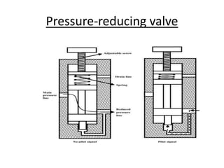

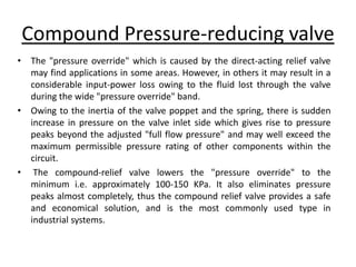
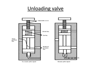

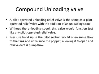


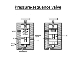


The document summarizes different types of pressure control valves used in hydraulic systems. It describes pressure relief valves, pressure reducing valves, unloading valves, counterbalance valves, and pressure sequence valves. Each type of valve is explained in terms of its working, symbol, and purpose of controlling pressure in hydraulic circuits. Compound versions of some valves are also discussed.


