2 b industrial hydraulic circuits
•Download as PPTX, PDF•
0 likes•204 views

industrial hydraulic circuits

Recommended
More Related Content
What's hot
What's hot (20)
Similar to 2 b industrial hydraulic circuits
Similar to 2 b industrial hydraulic circuits (20)
More from Dr.R. SELVAM
More from Dr.R. SELVAM (20)
Recently uploaded
Recently uploaded (20)
2 b industrial hydraulic circuits
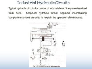
- 1. Industrial HydraulicCircuits Typical hydraulic circuits for control of industrial machinery are described from here. Graphical hydraulic circuit diagrams incorporating component symbols are used to explain the operation of the circuits.
- 2. Unloading System for Energy Saving An “unloading” system is used to divert pump flow to a tank during part of the operational cycle to reduce power demand. This is done to avoid wasting power idle periods. For example, it is often desirable to combine the delivery of two pumps to achieve higher flow rates for higher speed while a cylinder is advancing at low pressure. However, there may be considerable portions of the cycle, such as when the cylinder is moving a heavy load, when the high speed is no longer required, or cannot be sustained by the prime mover. Therefore, one of the two pumps is to be unloaded resulting in a reduction of speed and consequently, power. The components of this system are: A, B: Hydraulic pumps, C, E: Pilot operated Spring loaded Relief valves,D: Check valve
- 3. Mode 1: Both PumpsLoaded In Figure, when both pumps are delivering, oil from the pump A passes through the unloading valve Cand the check valve D to combine with the pump B output. This continues so long as system pressure is lower than the setting of the unloading valve Mode 2: One pump unloaded In Fig., when system pressure exceeds the setting of the unloading valve C, it makes pump A to discharge to the tank at little pressure. Although the system pressure, supplied by pump B, is high, the check valve prevents flow from B through the unloading valve. Thus only pump B now drives the load at its own delivery rate. Thus the load motion becomes slower but the power demand on the motor M also reduces.
- 4. Reciprocating Cylinder with Automatic Venting at End of Cycle A reciprocating cylinder drive is a very common hydraulic system. In systems where it is not necessary to hold pressure at the end of a cycle, it is desirable to unload the pump by automatically venting the relief valve, to save energy. Figures below show such a system. The system components are : A : Reservoir with Filter, B : Hydraulic pump, C, E : Check valve, D : Pilot operated relief valve, F : Two-position electro- hydraulic pilot operated Four-way Directional valve, G : Cam operated pilot valve, H : Double acting Single rod Cylinder, I : Limit Switch.
- 5. Extension Stroke Consider the beginning of the machine cycle when the solenoid of the spring offset directional valve F is energized. Pump output is connected to the cap end of the cylinder. The vent line drawn from the directional valve output connected to the cap end of the cylinder is blocked at the cam-operated pilot valve G. Thus, vent port of the relief valve D is blocked, and the cylinder moves under full pump pressureapplied to the capend. RetractionStroke At the extreme end of the extension stroke, the limit switch is made on by the cylinder rod to break the solenoid circuit for the directional valve F . The directional valve now shifts to its right position and the pump gets connected to the rod end of the cylinder which now retracts. Note that the relief valve vent connection is still blocked. extension
- 6. Automatic Venting at End of Retraction Stroke At the extreme end of the retraction stroke, the cam on the cylinder is operated by the rod to shift valve G. The relief valve vent port is thus connected, through E and G, to the line from the cap end of the cylinder, and to tank through the F and the inline check valve C. This vents the relief valve D and unloads thepump. PushButton Start of Cycle If another cycle of reciprocating motion is desired, a start button connected to the solenoid circuit is depressed to energize the solenoid, and, in turn, the directional valve shifts to direct pump output into the cap end of the cylinder. This causes the check valve in the vent line to close. Pressure again builds up and the cylinder starts extending. This releases the cam, which, under spring action, shifts and the vent port of Eis again blocked at G. Thus the cyclerepeats. retraction
- 7. PushButton Start of Cycle AutomaticVenting at Endof RetractionStroke
- 8. Regenerative ReciprocatingCircuit Conventional reciprocating circuits use a four-way directional valve connected directly to a cylinder. In a regenerative reciprocating circuit, oil from the rod end of the cylinder is directed into the cap end to increase speed, without requiring to increase pump flow. Such a circuit is shown below in Figures below. The circuit components are : A : Hydraulic Pump, B : Relief valve, C : Four-way two position solenoid operated valve, D : Double-acting Single-rod Cylinder. The operation of the regenerative circuit is shown in Figuresbelow.
- 9. RegenerativeAdvance In Figure, the “B” port on the directional valve C, which conventionally connects to the cylinder, is plugged and the rod end of the cylinder is connected directly to the pressure line. With the valve shifted to the left most position, the “P” port is connect to the cap end of the cylinder. If the ratio of cap end area to rod end annular area in the cylinder is 2:1, the pressure being the same at both end, the force at the cap end is double that at the rod end. There is therefore a net force on the cylinder to move the load. Similarly, at any speed of the cylinder, the flow into the cap end would be double that of the rod end. However, in this connection, the flow out of the rod end joins pump delivery to increase the cylinder speed. Thus only half of the flow into the cap end is actually supplied by the pump. However, the pressure during advance will be double the pressure required for a conventional arrangement for the same force requirement. This is because the same pressure in the rod end, effective over half the cap end area, opposes the cylinder’s advance.
- 10. In the reverse condition shown in Figure, flow from the pump directly enters the rod end of the cylinder through two parallel paths, one through the directional valve and the other directly. Exhaust flow from the cap end returns to the tank conventionally through the directional valve. Note that, in contrast to the conventional case, the force on the cylinder as well as the pump flow remains unchanged during extension and retraction. Thus, the speed of the piston during both advancement and retraction remain same.
- 11. SequencingCircuits In many applications, it is necessaryto perform operations in adefinite order. Following is one of several suchcircuits.Thecomponents of the systemareasfollows. A: Reservoir and Filter ; B: Hydraulic Pump ;C: ; Reliefvalve : D; F1,F2,G: Relief valve with integral checkvalve ; H,J: Cylinders; I :CheckValve Thesequenceof operation realized by the circuit shown in Figuresis: StepA– ExtendCylinder H Step B–ExtendCylinderJwhile holding pressureonCylinderH Step C–Retract Cylinder J Step D– RetractCylinderH
- 12. StepA Pressing a pushbutton would start the cycle and shift the directional valve E to the position shown in Fig. At first the fluid flows through the integral check valve in G into the cap end of H and returns freely through the check valve in F2. The pump pressure is low during this period, only to the extent ofpushing the load onH.
- 13. Step B Once H reaches its rod end, the pressure builds up and now the flow develops through F1 into the cap end of J and out through the rod end to go back directly to tank through F2, E and C. Note that a pressure equal to the setting of the valve F1 is maintained on H. When J is fully extended, pressure increases further and is limited by the setting of D, providing overload protection toB.
- 14. Step C Similarly, when the other solenoid of E is energized, the directional valve shifts to the other position, as shown in Fig. Now, pump delivery is directed through D, E and F2, into the rod end of J. As before, the flow out of the cap end of J flows to tank through F1, Eand C.Step C is illustrated inFig.
- 15. Power losses in flow control circuits. Energy losses in the current hydraulic systems, ranging between 30% and 50%, can no longer be accepted and therefore relevant scientific research carried out in the last 20 years has analysed the main causes, vulnerable places in the installations and ways to reduce them. In fact, energy losses are determined, among others, by the friction of the fluid layers between them and with the pipes through which they pass and by the pressuredrops on the equipment's, at bends and diameter changes. Finally all these cumulated hydraulic pressure losses turn into heat, and thus to the energy loss is also added the destructive action of the high temperature and the obligation to introduce additional cooling equipment in the system.
- 16. Power losses in componentsand systems In this section will be taken into consideration losses in pumps, distribution and control systems, pipes and hydraulicmotors. Losses in pumps are determined by internal losses and mechanical friction, and the total efficiency, which represents the energy efficiency, will be determined asthe product of volumetric efficiency and mechanical efficiency. An increase in the technological level of pumps manufacture, together with improved materials and increased tribological performances, made that the volumetric efficiency determined primarily by side clearances, as well as the mechanical efficiency determined by friction, both have values over 90%, so that in the end the total efficiency will also be over 90%.
- 17. ■ Losses in the distribution and control section are local losses determined by either construction of the equipment or the working methodology of the system. ■ If losses on every component can be treated as local losses and reduced by improving the forms of flow, within fairly narrow limits, technological losses recorded on flow control valves and regulators can be minimized through a proper design of the whole system and especiallythrough the useof adjustable pumps with high level of automation. ■ Upgrades in this area of a hydraulic system could lead to the greatest reductions in energy losses with current equipment's and technologies. In fact, the most important thing is to devise a system by which the discharges to the tank through the safety valve to be minimized. ■ Losses on pipelines and auxiliary components are generally quite high and are comprised of linear losses and losses on auxiliary equipment's such as filters, accumulators and coolers. ■ Generally, losses on auxiliary components can be treated as local losses with relatively small values, with rather small possibilities of reduction, as some of these components don’t permanently intervene into operation (accumulators),and others canbe bypassed.
- 18. ■ The big problem are the linear losses in the pipelines, which generally have high values and on which is working much and generally efficient. Designers choose the shortest routes, reducethem to the minimum, avoiding the forming of localareasof turbulence. ■ Energy losses in hydraulic motors are quite important, even though not essential. Losses in rotary motors are similar to energy losses in pumps because also in this case the one that counts is the tribological element and less the technological element, through which are produced at normal prices side clearances that can reduce internal flow losses. Hydraulic cylinders, with their component materials and the structure may reduce losses, but can not remove them. ■ In any case, in the cylinders used today in hydraulic systems, we find the friction between the rod and rod cap seal, between the piston and cylinder body and in the couplings by which the cylinder is attached to the mechanical equipment. Much important and more dangerous are the problems caused by a poor grip on the machine, because high radial forcesareintroduced which inducehigh friction andtherefore high power losses. ■ Switching-type digital hydraulics represents a solution of great interest which provides close proximity between the available flow rate and the required flow rate in each phase of work andalsogreatly reducesthe number of hydraulic equipment's for distribution and control. ■ Another great advantage is the reduced number of pipelines and hence linear losses. Otherwise the problem of the pumps andmotors issimilar toTypeCsystems.