SlideShare a Scribd company logo
The purpose of flow control in a hydraulic system is to regulate speed. All the devices
discussed here control the speed of an actuator by regulating the flow rate. Flow rate also
determines rate of energy transfer at any given pressure. The two are related in that the
actuator force multiplied by the distance through which it moves (stroke) equals the work
done on the load. The energy transferred must also equal the work done. Actuator speed
determines the rate of energy transfer (i.e., horsepower), and speed is thus a function of
flow rate.
Directional control, on the other hand, does not deal primarily with energy control, but
rather with directing the energy transfer system to the proper place in the system at the
proper time. Directional control valves can be thought of as fluid switches that make the
desired "contacts." That is, they direct the high-energy input stream to the actuator inlet and
provide a return path for the lower-energy oil.
It is of little consequence to control the energy transfer of the system through pressure and
flow controls if the flow stream does not arrive at the right place at the right time. Thus, a
secondary function of directional control devices might be defined as the timing of cycle
events. Because fluid flow often can be throttled in directional-control valves, some measure
of flow rate or pressure control can also be achieved with them.
Different types of flow measurement
Controlling flow of a fluid-power system does not necessarily mean regulating volume per
unit of time from a valve. Flow rate can be specified three different ways, so it is important
to be aware of how flow is to be specified or measured:
Volumetric flow rate, Qv, expressed in units of in.3/sec or min - or cc/sec or cc/min in SI
metric measure - is used to calculate the linear speeds of piston rods or rotational speeds of
motor shafts.
Weight flow rate, Qw, expressed in units of lb/sec or lb/min, is used to calculate power
using English units of measure.
Mass flow rate, Qg, expressed in units of slugs/sec or slugs/min for English measure - or
kg/sec or kg/min in SI metric measure - is used to calculate inertia forces during periods of
acceleration and deceleration.
Because they control the quantity of fluid that flows through the valve per unit of time, the
same control valves are used for all three types of flow rates.
Control of flow rate with valves
Fig. 1. Simple fixed orifice (a) and variable orifice (b) flow controls.
There are eight types of flow-control valves:
Orifices - A simple orifice in the line, Figure 1(a), is the most elementary method for
controlling flow. (Note that this is also a basic pressure control device.) When used to
control flow, the orifice is placed in series with the pump. An orifice can be a drilled hole in
a fitting, in which case it is fixed; or it may be a calibrated needle valve, in which case it
functions as a variable orifice, Figure 1(b). Both types are non-compensated flow-control
devices.
Fig. 2. Flow regulator adjusts to variations in inlet and output press ures.
Flow regulators - This device, Figure 2, which is slightly more sophisticated than a fixed
orifice, consists of an orifice that senses flow rate as a pressure drop across the orifice; a
compensating piston adjusts to variations in inlet and outlet pressures. This compensating
ability provides closer control of flow rate under varying pressure conditions. Control
accuracy may be 5%, possibly less with specially calibrated valves that operate around a
given flow-rate point.
Fig. 3. Bypass flow regulator returns excess flow from pump to tank.
Bypass flow regulators - In this flow regulator, flow in excess of set flow rate returns to
reservoir through a bypass port, Figure 3. Flow rate is controlled by throttling fluid across a
variable orifice regulated by the compensator piston. The bypass flow regulator is more
efficient than a standard flow regulator.
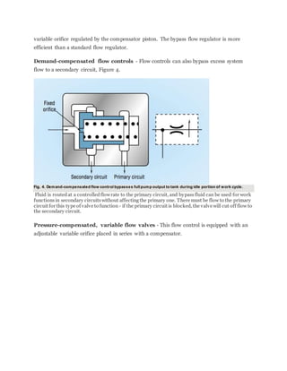
Demand-compensated flow controls - Flow controls can also bypass excess system
flow to a secondary circuit, Figure 4.
Fig. 4. Demand-compensated flow control bypasses full pump output to tank during idle portion of work cycle.
Fluid is routedat a controlledflowrate to the primary circuit, and bypassfluid can be used for work
functionsin secondary circuitswithout affectingthe primary one. There must be flow to the primary
circuit for this type of valve to function - if the primary circuit is blocked, the valve will cut off flow to
the secondary circuit.
Pressure-compensated, variable flow valves - This flow control is equipped with an
adjustable variable orifice placed in series with a compensator.
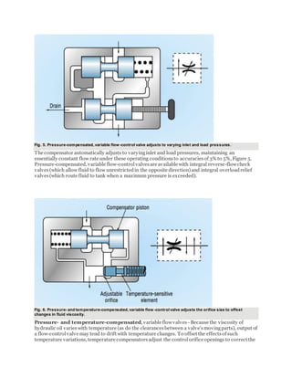
Fig. 5. Pressure-compensated, variable flow -control valve adjusts to varying inlet and load pressures.
The compensator automatically adjusts to varyinginlet and load pressures, maintaining an
essentially constant flow rate under these operating conditionsto accuraciesof 3% to 5%, Figure 5.
Pressure-compensated, variable flow-controlvalvesare available with integral reverse-flowcheck
valves(which allow fluid to flow unrestrictedin the opposite direction)and integral overloadrelief
valves(which route fluid to tank when a maximum pressure is exceeded).
Fig. 6. Pressure- and temperature-compensated, variable flow -control valve adjusts the orifice size to offset
changes in fluid viscosity.
Pressure- and temperature-compensated, variable flowvalves - Because the viscosity of
hydraulic oil varieswith temperature (as do the clearancesbetween a valve'smovingparts), output of
a flow-controlvalve may tend to drift with temperature changes. To offset the effectsof such
temperature variations, temperature compensatorsadjust the controlorifice openings to correct the
effectsof viscosity changescausedby temperature fluctuationsof the fluid, Figure 6. Thisis done in
combination with adjustments the controlorifice for pressure changes as well.
Fig. 7. Priority valve supplies fluid at a set rate to a primary circuit.
Priority valves - A priority valve, Figure 7, is essentially a flow-control valve that supplies
fluid at a set flow rate to the primary circuit, thus functioning as a pressure-compensated
flow-control valve. Flow in excess of that required by the primary circuit bypasses to a
secondary circuit at a pressure somewhat below that of the primary circuit. Should inlet or
load pressure (or both) vary, the primary circuit has priority over the secondary - as far as
supplying the design flow rate is concerned.
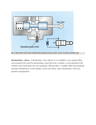
Fig. 8. Deceleration valve slows load by being gradually closed by action of cam mounted on cylinder load.
Deceleration valves - A deceleration valve, Figure 8, is a modified 2-way, spring-offset,
cam actuated valve used for decelerating a load driven by a cylinder. A cam attached to the
cylinder rod or load closes the valve gradually. This provides a variable orifice that gradually
increases backpressure in the cylinder as the valve closes. Some deceleration valves are
pressure-compensated.

More Related Content

What's hot

Pneumatic valves
Pneumatic valvesPneumatic valves
Pneumatic valves
Waqar Aziz
 
UNIT 2 PPT
UNIT 2 PPTUNIT 2 PPT
UNIT 2 PPT
gopalkrishnan202
 
Hydraulic ciruits
Hydraulic ciruitsHydraulic ciruits
Hydraulic ciruits
Abhishek Patange
 
Hydraulic systems
Hydraulic  systemsHydraulic  systems
Hydraulic systems
Thulasikanth Vaddi
 
Flow control valves
Flow control valvesFlow control valves
Flow control valves
waleedkhaled144
 
What Is Hydraulic Filter?
What Is Hydraulic Filter?What Is Hydraulic Filter?
What Is Hydraulic Filter?
payalkataria01
 
System Components, Hydraulic Oils, Fluid Properties and Filter
System Components, Hydraulic Oils, Fluid Properties and FilterSystem Components, Hydraulic Oils, Fluid Properties and Filter
System Components, Hydraulic Oils, Fluid Properties and Filter
RAHUL THAKER
 
Servo Valves
Servo Valves Servo Valves
Servo Valves
Sarthak Muttha
 
4 fluid power ansi symbols
4 fluid power ansi symbols4 fluid power ansi symbols
4 fluid power ansi symbols
Dr.R. SELVAM
 
Overview of control valves
Overview of control valvesOverview of control valves
Overview of control valves
YALAMANCHILI ASHOK KUMAR
 
Industrial hydraulics
Industrial hydraulicsIndustrial hydraulics
Pressure control valves
Pressure control valvesPressure control valves
Pressure control valves
Shrenik Baid
 
Introduction to Pneumatic Systems
Introduction to Pneumatic SystemsIntroduction to Pneumatic Systems
Introduction to Pneumatic Systems
RAHUL THAKER
 
Hydraulic Circuit Design and Analysis , dr.samir elshamy
Hydraulic Circuit Design and Analysis , dr.samir elshamyHydraulic Circuit Design and Analysis , dr.samir elshamy
Hydraulic Circuit Design and Analysis , dr.samir elshamy
Dr.Samir el-shamy
 
HYDRAULICS AND PNEUMATICS (UNIT 4)
HYDRAULICS AND PNEUMATICS   (UNIT 4)HYDRAULICS AND PNEUMATICS   (UNIT 4)
HYDRAULICS AND PNEUMATICS (UNIT 4)
kannanmuthu11
 
Pneumatic rotary actuators
Pneumatic rotary actuatorsPneumatic rotary actuators
Pneumatic rotary actuators
Akshay Bedwal
 
HP UNIT 4 PPT
HP UNIT 4 PPT HP UNIT 4 PPT
HP UNIT 4 PPT
gopalkrishnan202
 
Basics of valves
Basics of valvesBasics of valves
Basics of valves
Tahseen Qamhieh
 

What's hot (20)

Pneumatic valves
Pneumatic valvesPneumatic valves
Pneumatic valves
 
Hydraulic course manual
Hydraulic course manualHydraulic course manual
Hydraulic course manual
 
UNIT 2 PPT
UNIT 2 PPTUNIT 2 PPT
UNIT 2 PPT
 
Hydraulic ciruits
Hydraulic ciruitsHydraulic ciruits
Hydraulic ciruits
 
Hydraulic systems
Hydraulic  systemsHydraulic  systems
Hydraulic systems
 
Flow control valves
Flow control valvesFlow control valves
Flow control valves
 
What Is Hydraulic Filter?
What Is Hydraulic Filter?What Is Hydraulic Filter?
What Is Hydraulic Filter?
 
System Components, Hydraulic Oils, Fluid Properties and Filter
System Components, Hydraulic Oils, Fluid Properties and FilterSystem Components, Hydraulic Oils, Fluid Properties and Filter
System Components, Hydraulic Oils, Fluid Properties and Filter
 
Servo Valves
Servo Valves Servo Valves
Servo Valves
 
4 fluid power ansi symbols
4 fluid power ansi symbols4 fluid power ansi symbols
4 fluid power ansi symbols
 
Overview of control valves
Overview of control valvesOverview of control valves
Overview of control valves
 
Industrial hydraulics
Industrial hydraulicsIndustrial hydraulics
Industrial hydraulics
 
Pressure control valves
Pressure control valvesPressure control valves
Pressure control valves
 
Introduction to Pneumatic Systems
Introduction to Pneumatic SystemsIntroduction to Pneumatic Systems
Introduction to Pneumatic Systems
 
Hydraulic Circuit Design and Analysis , dr.samir elshamy
Hydraulic Circuit Design and Analysis , dr.samir elshamyHydraulic Circuit Design and Analysis , dr.samir elshamy
Hydraulic Circuit Design and Analysis , dr.samir elshamy
 
HYDRAULICS AND PNEUMATICS (UNIT 4)
HYDRAULICS AND PNEUMATICS   (UNIT 4)HYDRAULICS AND PNEUMATICS   (UNIT 4)
HYDRAULICS AND PNEUMATICS (UNIT 4)
 
Pneumatic rotary actuators
Pneumatic rotary actuatorsPneumatic rotary actuators
Pneumatic rotary actuators
 
HP UNIT 4 PPT
HP UNIT 4 PPT HP UNIT 4 PPT
HP UNIT 4 PPT
 
Basics of valves
Basics of valvesBasics of valves
Basics of valves
 
Basic hydraulic circuit
Basic hydraulic circuitBasic hydraulic circuit
Basic hydraulic circuit
 

Similar to Flow controll valve

Anti surge control
Anti surge controlAnti surge control
Anti surge control
achueth
 
chter 3 actuators.pdffejvrvfdvkceckevsvd
chter 3 actuators.pdffejvrvfdvkceckevsvdchter 3 actuators.pdffejvrvfdvkceckevsvd
chter 3 actuators.pdffejvrvfdvkceckevsvd
AdugnaGosa1
 
2 c industrial hydraulic circuits
2 c industrial hydraulic circuits2 c industrial hydraulic circuits
2 c industrial hydraulic circuits
Dr.R. SELVAM
 
cascade and ratio control word doc
cascade and ratio control word doccascade and ratio control word doc
cascade and ratio control word docUmer Farooq
 
hydralics lec10 (1).pptx
hydralics lec10 (1).pptxhydralics lec10 (1).pptx
hydralics lec10 (1).pptx
Liga8
 
steam turbine govering system
steam turbine govering systemsteam turbine govering system
steam turbine govering systemmitravanu mishra
 
Hydraulic systems report
Hydraulic systems  reportHydraulic systems  report
Hydraulic systems report
nagaraju kondrasi
 
Instrument & control
Instrument & controlInstrument & control
Instrument & control
M Randi Rj VoreCastle
 
Boiler drum's water level control
Boiler drum's water level controlBoiler drum's water level control
Boiler drum's water level control
Mukul kashiwal
 
Cascade pid controllers
Cascade pid controllersCascade pid controllers
Cascade pid controllers
ahshamseldin
 
DOC-20240201-WA0004..pdf
DOC-20240201-WA0004..pdfDOC-20240201-WA0004..pdf
DOC-20240201-WA0004..pdf
AbhayKumar653638
 
Chapter six hydraulic circuit design and analysis.pptx
Chapter six  hydraulic circuit design and analysis.pptxChapter six  hydraulic circuit design and analysis.pptx
Chapter six hydraulic circuit design and analysis.pptx
nurcam1
 
3 valve shafts pneumatics and hydraulics
3 valve shafts pneumatics and hydraulics3 valve shafts pneumatics and hydraulics
3 valve shafts pneumatics and hydraulics
aman520305
 
Aircraft hydraulics
Aircraft hydraulicsAircraft hydraulics
Aircraft hydraulics
vungtauairport
 
Boiler doc 06 control valve & actuator
Boiler doc 06   control valve & actuatorBoiler doc 06   control valve & actuator
Boiler doc 06 control valve & actuatorMars Tsani
 
Boiler doc 06 control valve & actuator
Boiler doc 06   control valve & actuatorBoiler doc 06   control valve & actuator
Boiler doc 06 control valve & actuatorMars Tsani
 
3.10 valves modeling dynamics - engineering libre-texts
3.10  valves   modeling dynamics - engineering libre-texts3.10  valves   modeling dynamics - engineering libre-texts
3.10 valves modeling dynamics - engineering libre-texts
Kyriakos Michalaki
 
MODELLING CASCADED SPLIT RANGE (CASC-SRC) CONTROLLERS IN ASPEN HYSYS DYNAMICS
MODELLING CASCADED SPLIT RANGE (CASC-SRC) CONTROLLERS IN ASPEN HYSYS DYNAMICSMODELLING CASCADED SPLIT RANGE (CASC-SRC) CONTROLLERS IN ASPEN HYSYS DYNAMICS
MODELLING CASCADED SPLIT RANGE (CASC-SRC) CONTROLLERS IN ASPEN HYSYS DYNAMICS
Vijay Sarathy
 

Similar to Flow controll valve (20)

Anti surge control
Anti surge controlAnti surge control
Anti surge control
 
chter 3 actuators.pdffejvrvfdvkceckevsvd
chter 3 actuators.pdffejvrvfdvkceckevsvdchter 3 actuators.pdffejvrvfdvkceckevsvd
chter 3 actuators.pdffejvrvfdvkceckevsvd
 
2 c industrial hydraulic circuits
2 c industrial hydraulic circuits2 c industrial hydraulic circuits
2 c industrial hydraulic circuits
 
cascade and ratio control word doc
cascade and ratio control word doccascade and ratio control word doc
cascade and ratio control word doc
 
hydralics lec10 (1).pptx
hydralics lec10 (1).pptxhydralics lec10 (1).pptx
hydralics lec10 (1).pptx
 
steam turbine govering system
steam turbine govering systemsteam turbine govering system
steam turbine govering system
 
Hydraulic systems report
Hydraulic systems  reportHydraulic systems  report
Hydraulic systems report
 
Instrument & control
Instrument & controlInstrument & control
Instrument & control
 
Boiler drum's water level control
Boiler drum's water level controlBoiler drum's water level control
Boiler drum's water level control
 
Cascade pid controllers
Cascade pid controllersCascade pid controllers
Cascade pid controllers
 
DOC-20240201-WA0004..pdf
DOC-20240201-WA0004..pdfDOC-20240201-WA0004..pdf
DOC-20240201-WA0004..pdf
 
Pneumatic c5
Pneumatic c5Pneumatic c5
Pneumatic c5
 
Chapter six hydraulic circuit design and analysis.pptx
Chapter six  hydraulic circuit design and analysis.pptxChapter six  hydraulic circuit design and analysis.pptx
Chapter six hydraulic circuit design and analysis.pptx
 
3 valve shafts pneumatics and hydraulics
3 valve shafts pneumatics and hydraulics3 valve shafts pneumatics and hydraulics
3 valve shafts pneumatics and hydraulics
 
Aircraft hydraulics
Aircraft hydraulicsAircraft hydraulics
Aircraft hydraulics
 
Boiler doc 06 control valve & actuator
Boiler doc 06   control valve & actuatorBoiler doc 06   control valve & actuator
Boiler doc 06 control valve & actuator
 
Boiler doc 06 control valve & actuator
Boiler doc 06   control valve & actuatorBoiler doc 06   control valve & actuator
Boiler doc 06 control valve & actuator
 
3.10 valves modeling dynamics - engineering libre-texts
3.10  valves   modeling dynamics - engineering libre-texts3.10  valves   modeling dynamics - engineering libre-texts
3.10 valves modeling dynamics - engineering libre-texts
 
MODELLING CASCADED SPLIT RANGE (CASC-SRC) CONTROLLERS IN ASPEN HYSYS DYNAMICS
MODELLING CASCADED SPLIT RANGE (CASC-SRC) CONTROLLERS IN ASPEN HYSYS DYNAMICSMODELLING CASCADED SPLIT RANGE (CASC-SRC) CONTROLLERS IN ASPEN HYSYS DYNAMICS
MODELLING CASCADED SPLIT RANGE (CASC-SRC) CONTROLLERS IN ASPEN HYSYS DYNAMICS
 
Hydrostatic transmission
Hydrostatic transmissionHydrostatic transmission
Hydrostatic transmission
 

Recently uploaded

Planning Of Procurement o different goods and services
Planning Of Procurement o different goods and servicesPlanning Of Procurement o different goods and services
Planning Of Procurement o different goods and services
JoytuBarua2
 
road safety engineering r s e unit 3.pdf
road safety engineering  r s e unit 3.pdfroad safety engineering  r s e unit 3.pdf
road safety engineering r s e unit 3.pdf
VENKATESHvenky89705
 
weather web application report.pdf
weather web application report.pdfweather web application report.pdf
weather web application report.pdf
Pratik Pawar
 
Railway Signalling Principles Edition 3.pdf
Railway Signalling Principles Edition 3.pdfRailway Signalling Principles Edition 3.pdf
Railway Signalling Principles Edition 3.pdf
TeeVichai
 
MCQ Soil mechanics questions (Soil shear strength).pdf
MCQ Soil mechanics questions (Soil shear strength).pdfMCQ Soil mechanics questions (Soil shear strength).pdf
MCQ Soil mechanics questions (Soil shear strength).pdf
Osamah Alsalih
 
Water Industry Process Automation and Control Monthly - May 2024.pdf
Water Industry Process Automation and Control Monthly - May 2024.pdfWater Industry Process Automation and Control Monthly - May 2024.pdf
Water Industry Process Automation and Control Monthly - May 2024.pdf
Water Industry Process Automation & Control
 
Top 10 Oil and Gas Projects in Saudi Arabia 2024.pdf
Top 10 Oil and Gas Projects in Saudi Arabia 2024.pdfTop 10 Oil and Gas Projects in Saudi Arabia 2024.pdf
Top 10 Oil and Gas Projects in Saudi Arabia 2024.pdf
Teleport Manpower Consultant
 
一比一原版(UofT毕业证)多伦多大学毕业证成绩单如何办理
一比一原版(UofT毕业证)多伦多大学毕业证成绩单如何办理一比一原版(UofT毕业证)多伦多大学毕业证成绩单如何办理
一比一原版(UofT毕业证)多伦多大学毕业证成绩单如何办理
ydteq
 
Hybrid optimization of pumped hydro system and solar- Engr. Abdul-Azeez.pdf
Hybrid optimization of pumped hydro system and solar- Engr. Abdul-Azeez.pdfHybrid optimization of pumped hydro system and solar- Engr. Abdul-Azeez.pdf
Hybrid optimization of pumped hydro system and solar- Engr. Abdul-Azeez.pdf
fxintegritypublishin
 
WATER CRISIS and its solutions-pptx 1234
WATER CRISIS and its solutions-pptx 1234WATER CRISIS and its solutions-pptx 1234
WATER CRISIS and its solutions-pptx 1234
AafreenAbuthahir2
 
在线办理(ANU毕业证书)澳洲国立大学毕业证录取通知书一模一样
在线办理(ANU毕业证书)澳洲国立大学毕业证录取通知书一模一样在线办理(ANU毕业证书)澳洲国立大学毕业证录取通知书一模一样
在线办理(ANU毕业证书)澳洲国立大学毕业证录取通知书一模一样
obonagu
 
Governing Equations for Fundamental Aerodynamics_Anderson2010.pdf
Governing Equations for Fundamental Aerodynamics_Anderson2010.pdfGoverning Equations for Fundamental Aerodynamics_Anderson2010.pdf
Governing Equations for Fundamental Aerodynamics_Anderson2010.pdf
WENKENLI1
 
Cosmetic shop management system project report.pdf
Cosmetic shop management system project report.pdfCosmetic shop management system project report.pdf
Cosmetic shop management system project report.pdf
Kamal Acharya
 
Standard Reomte Control Interface - Neometrix
Standard Reomte Control Interface - NeometrixStandard Reomte Control Interface - Neometrix
Standard Reomte Control Interface - Neometrix
Neometrix_Engineering_Pvt_Ltd
 
Investor-Presentation-Q1FY2024 investor presentation document.pptx
Investor-Presentation-Q1FY2024 investor presentation document.pptxInvestor-Presentation-Q1FY2024 investor presentation document.pptx
Investor-Presentation-Q1FY2024 investor presentation document.pptx
AmarGB2
 
The role of big data in decision making.
The role of big data in decision making.The role of big data in decision making.
The role of big data in decision making.
ankuprajapati0525
 
H.Seo, ICLR 2024, MLILAB, KAIST AI.pdf
H.Seo,  ICLR 2024, MLILAB,  KAIST AI.pdfH.Seo,  ICLR 2024, MLILAB,  KAIST AI.pdf
H.Seo, ICLR 2024, MLILAB, KAIST AI.pdf
MLILAB
 
The Benefits and Techniques of Trenchless Pipe Repair.pdf
The Benefits and Techniques of Trenchless Pipe Repair.pdfThe Benefits and Techniques of Trenchless Pipe Repair.pdf
The Benefits and Techniques of Trenchless Pipe Repair.pdf
Pipe Restoration Solutions
 
ethical hacking-mobile hacking methods.ppt
ethical hacking-mobile hacking methods.pptethical hacking-mobile hacking methods.ppt
ethical hacking-mobile hacking methods.ppt
Jayaprasanna4
 
block diagram and signal flow graph representation
block diagram and signal flow graph representationblock diagram and signal flow graph representation
block diagram and signal flow graph representation
Divya Somashekar
 

Recently uploaded (20)

Planning Of Procurement o different goods and services
Planning Of Procurement o different goods and servicesPlanning Of Procurement o different goods and services
Planning Of Procurement o different goods and services
 
road safety engineering r s e unit 3.pdf
road safety engineering  r s e unit 3.pdfroad safety engineering  r s e unit 3.pdf
road safety engineering r s e unit 3.pdf
 
weather web application report.pdf
weather web application report.pdfweather web application report.pdf
weather web application report.pdf
 
Railway Signalling Principles Edition 3.pdf
Railway Signalling Principles Edition 3.pdfRailway Signalling Principles Edition 3.pdf
Railway Signalling Principles Edition 3.pdf
 
MCQ Soil mechanics questions (Soil shear strength).pdf
MCQ Soil mechanics questions (Soil shear strength).pdfMCQ Soil mechanics questions (Soil shear strength).pdf
MCQ Soil mechanics questions (Soil shear strength).pdf
 
Water Industry Process Automation and Control Monthly - May 2024.pdf
Water Industry Process Automation and Control Monthly - May 2024.pdfWater Industry Process Automation and Control Monthly - May 2024.pdf
Water Industry Process Automation and Control Monthly - May 2024.pdf
 
Top 10 Oil and Gas Projects in Saudi Arabia 2024.pdf
Top 10 Oil and Gas Projects in Saudi Arabia 2024.pdfTop 10 Oil and Gas Projects in Saudi Arabia 2024.pdf
Top 10 Oil and Gas Projects in Saudi Arabia 2024.pdf
 
一比一原版(UofT毕业证)多伦多大学毕业证成绩单如何办理
一比一原版(UofT毕业证)多伦多大学毕业证成绩单如何办理一比一原版(UofT毕业证)多伦多大学毕业证成绩单如何办理
一比一原版(UofT毕业证)多伦多大学毕业证成绩单如何办理
 
Hybrid optimization of pumped hydro system and solar- Engr. Abdul-Azeez.pdf
Hybrid optimization of pumped hydro system and solar- Engr. Abdul-Azeez.pdfHybrid optimization of pumped hydro system and solar- Engr. Abdul-Azeez.pdf
Hybrid optimization of pumped hydro system and solar- Engr. Abdul-Azeez.pdf
 
WATER CRISIS and its solutions-pptx 1234
WATER CRISIS and its solutions-pptx 1234WATER CRISIS and its solutions-pptx 1234
WATER CRISIS and its solutions-pptx 1234
 
在线办理(ANU毕业证书)澳洲国立大学毕业证录取通知书一模一样
在线办理(ANU毕业证书)澳洲国立大学毕业证录取通知书一模一样在线办理(ANU毕业证书)澳洲国立大学毕业证录取通知书一模一样
在线办理(ANU毕业证书)澳洲国立大学毕业证录取通知书一模一样
 
Governing Equations for Fundamental Aerodynamics_Anderson2010.pdf
Governing Equations for Fundamental Aerodynamics_Anderson2010.pdfGoverning Equations for Fundamental Aerodynamics_Anderson2010.pdf
Governing Equations for Fundamental Aerodynamics_Anderson2010.pdf
 
Cosmetic shop management system project report.pdf
Cosmetic shop management system project report.pdfCosmetic shop management system project report.pdf
Cosmetic shop management system project report.pdf
 
Standard Reomte Control Interface - Neometrix
Standard Reomte Control Interface - NeometrixStandard Reomte Control Interface - Neometrix
Standard Reomte Control Interface - Neometrix
 
Investor-Presentation-Q1FY2024 investor presentation document.pptx
Investor-Presentation-Q1FY2024 investor presentation document.pptxInvestor-Presentation-Q1FY2024 investor presentation document.pptx
Investor-Presentation-Q1FY2024 investor presentation document.pptx
 
The role of big data in decision making.
The role of big data in decision making.The role of big data in decision making.
The role of big data in decision making.
 
H.Seo, ICLR 2024, MLILAB, KAIST AI.pdf
H.Seo,  ICLR 2024, MLILAB,  KAIST AI.pdfH.Seo,  ICLR 2024, MLILAB,  KAIST AI.pdf
H.Seo, ICLR 2024, MLILAB, KAIST AI.pdf
 
The Benefits and Techniques of Trenchless Pipe Repair.pdf
The Benefits and Techniques of Trenchless Pipe Repair.pdfThe Benefits and Techniques of Trenchless Pipe Repair.pdf
The Benefits and Techniques of Trenchless Pipe Repair.pdf
 
ethical hacking-mobile hacking methods.ppt
ethical hacking-mobile hacking methods.pptethical hacking-mobile hacking methods.ppt
ethical hacking-mobile hacking methods.ppt
 
block diagram and signal flow graph representation
block diagram and signal flow graph representationblock diagram and signal flow graph representation
block diagram and signal flow graph representation
 

Flow controll valve

  • 1. The purpose of flow control in a hydraulic system is to regulate speed. All the devices discussed here control the speed of an actuator by regulating the flow rate. Flow rate also determines rate of energy transfer at any given pressure. The two are related in that the actuator force multiplied by the distance through which it moves (stroke) equals the work done on the load. The energy transferred must also equal the work done. Actuator speed determines the rate of energy transfer (i.e., horsepower), and speed is thus a function of flow rate. Directional control, on the other hand, does not deal primarily with energy control, but rather with directing the energy transfer system to the proper place in the system at the proper time. Directional control valves can be thought of as fluid switches that make the desired "contacts." That is, they direct the high-energy input stream to the actuator inlet and provide a return path for the lower-energy oil. It is of little consequence to control the energy transfer of the system through pressure and flow controls if the flow stream does not arrive at the right place at the right time. Thus, a secondary function of directional control devices might be defined as the timing of cycle events. Because fluid flow often can be throttled in directional-control valves, some measure of flow rate or pressure control can also be achieved with them. Different types of flow measurement Controlling flow of a fluid-power system does not necessarily mean regulating volume per unit of time from a valve. Flow rate can be specified three different ways, so it is important to be aware of how flow is to be specified or measured: Volumetric flow rate, Qv, expressed in units of in.3/sec or min - or cc/sec or cc/min in SI metric measure - is used to calculate the linear speeds of piston rods or rotational speeds of motor shafts. Weight flow rate, Qw, expressed in units of lb/sec or lb/min, is used to calculate power using English units of measure. Mass flow rate, Qg, expressed in units of slugs/sec or slugs/min for English measure - or kg/sec or kg/min in SI metric measure - is used to calculate inertia forces during periods of acceleration and deceleration.
  • 2. Because they control the quantity of fluid that flows through the valve per unit of time, the same control valves are used for all three types of flow rates. Control of flow rate with valves Fig. 1. Simple fixed orifice (a) and variable orifice (b) flow controls. There are eight types of flow-control valves: Orifices - A simple orifice in the line, Figure 1(a), is the most elementary method for controlling flow. (Note that this is also a basic pressure control device.) When used to control flow, the orifice is placed in series with the pump. An orifice can be a drilled hole in a fitting, in which case it is fixed; or it may be a calibrated needle valve, in which case it functions as a variable orifice, Figure 1(b). Both types are non-compensated flow-control devices.
  • 3. Fig. 2. Flow regulator adjusts to variations in inlet and output press ures. Flow regulators - This device, Figure 2, which is slightly more sophisticated than a fixed orifice, consists of an orifice that senses flow rate as a pressure drop across the orifice; a compensating piston adjusts to variations in inlet and outlet pressures. This compensating ability provides closer control of flow rate under varying pressure conditions. Control accuracy may be 5%, possibly less with specially calibrated valves that operate around a given flow-rate point. Fig. 3. Bypass flow regulator returns excess flow from pump to tank. Bypass flow regulators - In this flow regulator, flow in excess of set flow rate returns to reservoir through a bypass port, Figure 3. Flow rate is controlled by throttling fluid across a
  • 4. variable orifice regulated by the compensator piston. The bypass flow regulator is more efficient than a standard flow regulator. Demand-compensated flow controls - Flow controls can also bypass excess system flow to a secondary circuit, Figure 4. Fig. 4. Demand-compensated flow control bypasses full pump output to tank during idle portion of work cycle. Fluid is routedat a controlledflowrate to the primary circuit, and bypassfluid can be used for work functionsin secondary circuitswithout affectingthe primary one. There must be flow to the primary circuit for this type of valve to function - if the primary circuit is blocked, the valve will cut off flow to the secondary circuit. Pressure-compensated, variable flow valves - This flow control is equipped with an adjustable variable orifice placed in series with a compensator.
  • 5. Fig. 5. Pressure-compensated, variable flow -control valve adjusts to varying inlet and load pressures. The compensator automatically adjusts to varyinginlet and load pressures, maintaining an essentially constant flow rate under these operating conditionsto accuraciesof 3% to 5%, Figure 5. Pressure-compensated, variable flow-controlvalvesare available with integral reverse-flowcheck valves(which allow fluid to flow unrestrictedin the opposite direction)and integral overloadrelief valves(which route fluid to tank when a maximum pressure is exceeded). Fig. 6. Pressure- and temperature-compensated, variable flow -control valve adjusts the orifice size to offset changes in fluid viscosity. Pressure- and temperature-compensated, variable flowvalves - Because the viscosity of hydraulic oil varieswith temperature (as do the clearancesbetween a valve'smovingparts), output of a flow-controlvalve may tend to drift with temperature changes. To offset the effectsof such temperature variations, temperature compensatorsadjust the controlorifice openings to correct the
  • 6. effectsof viscosity changescausedby temperature fluctuationsof the fluid, Figure 6. Thisis done in combination with adjustments the controlorifice for pressure changes as well. Fig. 7. Priority valve supplies fluid at a set rate to a primary circuit. Priority valves - A priority valve, Figure 7, is essentially a flow-control valve that supplies fluid at a set flow rate to the primary circuit, thus functioning as a pressure-compensated flow-control valve. Flow in excess of that required by the primary circuit bypasses to a secondary circuit at a pressure somewhat below that of the primary circuit. Should inlet or load pressure (or both) vary, the primary circuit has priority over the secondary - as far as supplying the design flow rate is concerned.
  • 7. Fig. 8. Deceleration valve slows load by being gradually closed by action of cam mounted on cylinder load. Deceleration valves - A deceleration valve, Figure 8, is a modified 2-way, spring-offset, cam actuated valve used for decelerating a load driven by a cylinder. A cam attached to the cylinder rod or load closes the valve gradually. This provides a variable orifice that gradually increases backpressure in the cylinder as the valve closes. Some deceleration valves are pressure-compensated.