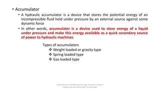
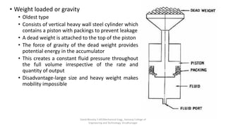
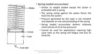
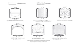
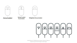
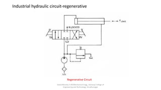
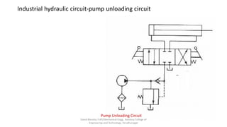
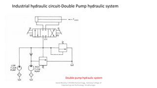
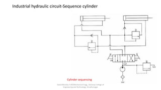
SlideShare a Scribd company logo
Hydraulic Circuits and Systems
Prepared by
David Blessley S
AP/Mechanical Engg.,
Kamaraj College of Engineering and Technology,
Virudhunagar.
David Blessley S AP/Mechanical Engg., Kamaraj College of
Engineering and Technology, Virudhunagar
Hydraulics and Pneumatics
• Accumulator
• A hydraulic accumulator is a device that stores the potential energy of an
incompressible fluid held under pressure by an external source against some
dynamic force
• In other words, accumulator is a device used to store energy of a liquid
under pressure and make this energy available as a quick secondary source
of power to hydraulic machines
Types of accumulators
❖ Weight loaded or gravity type
❖ Spring loaded type
❖ Gas loaded type
David Blessley S AP/Mechanical Engg., Kamaraj College of
Engineering and Technology, Virudhunagar
• Weight loaded or gravity
• Oldest type
• Consists of vertical heavy wall steel cylinder which
contains a piston with packings to prevent leakage
• A dead weight is attached to the top of the piston
• The force of gravity of the dead weight provides
potential energy in the accumulator
• This creates a constant fluid pressure throughout
the full volume irrespective of the rate and
quantity of output
• Disadvantage-large size and heavy weight makes
mobility impossible
David Blessley S AP/Mechanical Engg., Kamaraj College of
Engineering and Technology, Virudhunagar
• Spring loaded accumulator
• Similar to weight loaded except the piston is
preloaded with a spring
• The spring acting against the piston forces the
fluid into the system
• Pressure generated by this type is not constant
and depends on size and preloading of the spring
• Spring loaded accumulator delivers relatively
small volume of oil at low pressures
• Cannot be used for applications requiring high
cycle rates as the spring will fatigue and lose its
elasticity
David Blessley S AP/Mechanical Engg., Kamaraj College of
Engineering and Technology, Virudhunagar
• Gas loaded accumulator
• Operates on the principle of boyle’s law of gases-pressure
of a gas varies inversely with its volume
• i.e., gas volume of the accumulator would be cut in half if
the pressure is doubled
• Gas loaded accumulators are classified into two types
• Non separator type
• Separator type
• Piston type
• Bladder type
• Diaphragm type
• Non separator type
• Consists of a fully enclosed shell containing an oil port at
the bottom and a charging valve on the top
• Gas is confined at the top and oil at the bottom with no
physical separator between them
• Advantage- can handle large volume of oil
• Drawback- absorption of gas in oil due to lack of seperator
David Blessley S AP/Mechanical Engg., Kamaraj College of
Engineering and Technology, Virudhunagar
• Piston type
• Consists of a cylinder containing a freely floating
piston with seals
• Piston serves as barrier between gas and oil
• Threaded lock ring prevents disassembling of unit
while it is precharged
• Main drawback is expensive to manufacture
• Notable leakage may occur due to operation over
a long period of time
• Advantage is that its ability to handle very high or
low temperature system fluids through O-ring
seals
David Blessley S AP/Mechanical Engg., Kamaraj College of
Engineering and Technology, Virudhunagar
• Diaphragm type accumulator
• A diaphragm secured in the shell serves as an
elastic barrier between oil and gas
• A shutoff button, placed at the base of the
diaphragm covers the inlet when the diaphragm
is fully stretched
• On the gas side, a screw plug allows control of
the charge pressure and charging of the
accumulator by means of a charging and testing
device
• When the oil is delivered into the accumulator, it
deforms the diaphragm. The gas is compressed
when the charged oil pushes the diaphragm
against it
• This gas pressure is used as potential energy to
force the oil out when it is required in the circuit
• Drawback-doesnot provide constant fluid
pressure
David Blessley S AP/Mechanical Engg., Kamaraj College of
Engineering and Technology, Virudhunagar
• Bladder type accumulator
• Consists of an elastic barrier (bladder) between
the oil and gas
• This bladder is placed within the accumulator
shell and the balance of the space is filled with oil
• When the oil under pressure enters the
accumulator, the gas in the bladder gets
compressed
• When the oil is called on, the bladder expands
and forces the oil out into the circuit
• The large poppet valve placed at the fluid entry
port closes when the accumulator is exhausted.
This prevents the bladder from extruding out into
the inlet pipe.
David Blessley S AP/Mechanical Engg., Kamaraj College of
Engineering and Technology, Virudhunagar
David Blessley S AP/Mechanical Engg., Kamaraj College of
Engineering and Technology, Virudhunagar
David Blessley S AP/Mechanical Engg., Kamaraj College of
Engineering and Technology, Virudhunagar
• Intensifier
• Pressure intensifier or boosters are devices used to generate pressure greater than
those achievable with standard hydraulic pumps alone
• In other words, a hydraulic intensifier is a device which converts a large volume low
pressure fluid into a proportionally small volume high pressure fluid outlet
• The intensifier is usually placed in between the pump and the machine. It takes the
inlet flow from the pump and intensifies the pressure
• Its applications including hydraulic presses, riveting machine, spot welders etc.,
David Blessley S AP/Mechanical Engg., Kamaraj College of
Engineering and Technology, Virudhunagar
• It consists of two pistons low pressure and high pressure pistons having a
common piston rod
• The larger piston is exposed to pressure from a low pressure pump. The
low pressure oil forces the piston to move
• The smaller end of the piston exerts the same force on the fluid in the
intensifier chamber
• Intensifier ratio
Po x Ao = Pi x Ai
𝑷 𝒊
𝑷 𝒐
=
𝑨 𝒐
𝑨𝒊
David Blessley S AP/Mechanical Engg., Kamaraj College of
Engineering and Technology, Virudhunagar
Industrial hydraulic circuit-regenerative
Regenerative Circuit
David Blessley S AP/Mechanical Engg., Kamaraj College of
Engineering and Technology, Virudhunagar
Industrial hydraulic circuit-pump unloading circuit
Pump Unloading Circuit
David Blessley S AP/Mechanical Engg., Kamaraj College of
Engineering and Technology, Virudhunagar
Industrial hydraulic circuit-Double Pump hydraulic system
Double pump hydraulic system
David Blessley S AP/Mechanical Engg., Kamaraj College of
Engineering and Technology, Virudhunagar
Industrial hydraulic circuit-Sequence cylinder
Cylinder sequencing
David Blessley S AP/Mechanical Engg., Kamaraj College of
Engineering and Technology, Virudhunagar
Industrial hydraulic circuit-Automatic Cylinder Reciprocation system
Cylinder reciprocation system
David Blessley S AP/Mechanical Engg., Kamaraj College of
Engineering and Technology, Virudhunagar
Industrial hydraulic circuit-Synchronizing Circuit
David Blessley S AP/Mechanical Engg., Kamaraj College of
Engineering and Technology, Virudhunagar
Industrial hydraulic circuit-air over oil circuit
Air over oil circuit
David Blessley S AP/Mechanical Engg., Kamaraj College of
Engineering and Technology, Virudhunagar
Industrial hydraulic circuit-Fail-safe circuits
Protection from Inadvertent cylinder extension
David Blessley S AP/Mechanical Engg., Kamaraj College of
Engineering and Technology, Virudhunagar
Industrial hydraulic circuit-Fail-safe circuits-contd.,
Fail safe system with overload protection
David Blessley S AP/Mechanical Engg., Kamaraj College of
Engineering and Technology, Virudhunagar
Industrial hydraulic circuit-Fail-safe circuits-contd.,
Two handed safety circuit
David Blessley S AP/Mechanical Engg., Kamaraj College of
Engineering and Technology, Virudhunagar
Industrial hydraulic circuit-Speed control
Speed control-Metre In circuit Speed control-Metre Out circuit
David Blessley S AP/Mechanical Engg., Kamaraj College of
Engineering and Technology, Virudhunagar
• Hydromechanical servo valve
• A small force applied on the main spool
shifts it towards right which allows oil to
enter through port P1 from inlet
• Oil from inlet port enters P1 and causes the
cylinder to retract towards right.
• As shown in fig. a feedback link is
connected to the piston rod and sliding
sleeve which shifts the sliding sleeve
towards right until it blocks off the flow to
Port P1
• Thus the given input motion has produced
a specific output motion and the output
motion is feedback to modify the input
through feedback line
Lap conditions
Closed centre servo valve : lands are larger than
ports
Open centre servo valve : lands are narrower
than port
Zero lap servo valve : both lands and edges are
made preciseDavid Blessley S AP/Mechanical Engg., Kamaraj College of
Engineering and Technology, Virudhunagar
• Hydromechanical servo valve in
steering applications
• Input force is the turning of the steering
wheel
• Steering wheel movement permits the
sliding sleeve to allow oil from port to the
steering cylinder which in turn moves the
wheel through steering linkage
• Since the valve spool is attached to the
linkage, it also moves along with the
linkage
• When the valve spool has moved far
enough, it cuts off the flow to the cylinder
by blocking the port. Thus the motion of
the cylinder is stopped
Thus the given input force (Steering wheel movement) has produced a specific output
motion(wheel movement) and the output motion is feedback to modify the input
through feedback line David Blessley S AP/Mechanical Engg., Kamaraj College of
Engineering and Technology, Virudhunagar
• Electrohydraulic servo valve
• The electrohydraulic servo valve operates due to
an electric signal to its torque motor which
positions the spool of the DC valve. In simple,
the electrical signal is used as an input signal to
control the hydraulic output
• Single stage electrohydraulic servo valve
• An electric signal is passed through the coils of a
torque motor
• The torque motor produces an armature
deflection depend on the input current
• Since the armature of the torque motor is
directly connected to the valve spool, the spool
also shifts by a distance proportional to the
change in current.
David Blessley S AP/Mechanical Engg., Kamaraj College of
Engineering and Technology, Virudhunagar
• Two stage electrohydraulic servo valve
• It consist of a main stage and a pilot stage
• The input signal produces an armature deflection
proportional to the input current
• The armature deflection is mechanically transmitted
to the pilot spool by means of a stiff wire
• If suppose the electrical signal causes the pilot spool
to shift towards left, the land X allows oil flow to end
B of the main spool which causes the main spool to
move towards right, which in turn pushes the sleeve
towards right
• The main valve stops moving when the hole in the
pilot sleeve exactly aligns with the land on the spool
(a feedback link connects the main spool and pilot
sliding sleeve. Thus any movement of the main spool is
fed back to the pilot spool sleeve)
David Blessley S AP/Mechanical Engg., Kamaraj College of
Engineering and Technology, Virudhunagar
• Jet pipe electrohydraulic servo valve
• A jet pipe is mechanically linked to the main
spool as in fig.
• The pilot pressure is applied to a jet pipe
which directs the flow into two pilot lines
• The amount of flow in these two pilot lines
vary depending on the input electrical control
signal i.e., the control signal diverts the jet
flow into two unequal flows
• The main spool moves towards less pressure
side. The spool movement stops when the jet
pipe is centrally located over the two pilot
pipes
David Blessley S AP/Mechanical Engg., Kamaraj College of
Engineering and Technology, Virudhunagar
• Flapper jet electrohydraulic servo valve
• A pilot pressure is applied to both the ends of
the main spool
• The sliding spool is actuated by pressure
difference between each end
• The pilot pressure lines are linked with two
opposing jet nozzles against a flapper valve
• The input signal produces and armature
deflection which in turn deflects the flapper
towards one of the jet nozzles causes the
pressure imbalance
• Now the main spool moves until the pressure is
balanced on both the ends
David Blessley S AP/Mechanical Engg., Kamaraj College of
Engineering and Technology, Virudhunagar
• Proportional valves
• Its types are
• Proportional pressure relief valve
• Proportional pressure reducing valve
• Proportional direction control valve
• Proportional pressure relief valve
• Works same as conventional pressure relief valve but springs are replaced by
proportional solenoid
• The input current to the solenoid energizes the coil and produces an armature
deflection proportional to the input current
• This armature deflection exerts a force on the poppet. The poppet keeps the valve
closed until the inlet pressure at port P overcomes the force by armature deflection
• When the inlet pressure overcomes this, the poppet valve opens and thus varies the
pressure of the valve
David Blessley S AP/Mechanical Engg., Kamaraj College of
Engineering and Technology, Virudhunagar
• Proportional pressure reducing valve
• Works same as conventional pressure
reducing valve but the spring is replaced
by proportional solenoid
• When the solenoid is energized, the
armature will deflect and move the spool
towards right.
• This action opens control orifice A and
allow flow from A to port X
• The outlet pressure of this valve depends
on the opening of control orifices A and B
which in turn depends on the input
current to solenoid
• Thus by proportionally varying the input
current, the operating pressures can be
reduced
David Blessley S AP/Mechanical Engg., Kamaraj College of
Engineering and Technology, Virudhunagar
• Proportional direction control valve
• When solenoid 1 is energized, the pressure is applied
to port X. This causes the spool to move towards right
against spring pressure
• It allows fluid flow from port P to port B and from port
A to T
• When the solenoid is deenergized, the control spring
centralizes the spool back to normal position
• Similarly, when solenoid 2 is energized, the pressure is
applied to port Y which causes spool to move towards
left against spring pressure.
• Now fluid flows from port p to A and port B to T. when
de-energizes, the spring centralizes the spool to
normal
David Blessley S AP/Mechanical Engg., Kamaraj College of
Engineering and Technology, Virudhunagar

More Related Content

What's hot

Lecture 18 directional valves and symbols
Lecture 18   directional valves and symbolsLecture 18   directional valves and symbols
Lecture 18 directional valves and symbols
Manipal Institute of Technology
 
DIRECTION CONTROL VALVE
DIRECTION CONTROL VALVEDIRECTION CONTROL VALVE
DIRECTION CONTROL VALVE
gopalkrishnan202
 
Actuators in hydraulic system
Actuators in hydraulic systemActuators in hydraulic system
Actuators in hydraulic system
Ashish Kamble
 
servo-valves
 servo-valves servo-valves
servo-valves
gopalkrishnan202
 
Hydraulic actuator presentation
Hydraulic actuator presentationHydraulic actuator presentation
Hydraulic actuator presentation
Akshay Hase
 
Hydraulic Valves (Valves) (Pneumatics also)
Hydraulic Valves (Valves) (Pneumatics also)Hydraulic Valves (Valves) (Pneumatics also)
Hydraulic Valves (Valves) (Pneumatics also)
Mohammad Azam Khan
 
Hydraulic system
Hydraulic systemHydraulic system
Hydraulic system
Bhavesh Solanki
 
Hydraulics
HydraulicsHydraulics
Hydraulics
Jinesh Patel
 
Pressure control valves
Pressure control valvesPressure control valves
Pressure control valves
Shrenik Baid
 
Hydraulic intensifier
Hydraulic  intensifierHydraulic  intensifier
Hydraulic intensifier
Prasanta Kumar Behera
 
UNIT 2 PPT
UNIT 2 PPTUNIT 2 PPT
UNIT 2 PPT
gopalkrishnan202
 
ME6021 - HYDRAULICS AND PNEUMATICS / UNIT I - FLUID POWER PRINCIPLES AND FUN...
ME6021 - HYDRAULICS AND PNEUMATICS / UNIT I -  FLUID POWER PRINCIPLES AND FUN...ME6021 - HYDRAULICS AND PNEUMATICS / UNIT I -  FLUID POWER PRINCIPLES AND FUN...
ME6021 - HYDRAULICS AND PNEUMATICS / UNIT I - FLUID POWER PRINCIPLES AND FUN...
SANTHOSH00775
 
Module 3 hydraulic control valves
Module 3 hydraulic control valvesModule 3 hydraulic control valves
Module 3 hydraulic control valves
srinivaspp
 
Hydraulics and pneumatics
Hydraulics and pneumaticsHydraulics and pneumatics
Hydraulics and pneumatics
rampal singh
 
HYDRAULICS AND PNEUMATICS (UNIT 4)
HYDRAULICS AND PNEUMATICS   (UNIT 4)HYDRAULICS AND PNEUMATICS   (UNIT 4)
HYDRAULICS AND PNEUMATICS (UNIT 4)
kannanmuthu11
 
Hydraulic Symbols introduction
Hydraulic Symbols introductionHydraulic Symbols introduction
Hydraulic Symbols introduction
Prashant Kakade
 
Hydraulic systems
Hydraulic  systemsHydraulic  systems
Hydraulic systems
Thulasikanth Vaddi
 
1 accumulators and intensifiers
1 accumulators and intensifiers1 accumulators and intensifiers
1 accumulators and intensifiers
Dr.R. SELVAM
 
Introduction of Oil hydraulics and pneumatic
Introduction of  Oil hydraulics and pneumaticIntroduction of  Oil hydraulics and pneumatic
Introduction of Oil hydraulics and pneumatic
RAHUL THAKER
 
Hydraulic actuators and control components
Hydraulic actuators and control componentsHydraulic actuators and control components
Hydraulic actuators and control components
david blessley
 

What's hot (20)

Lecture 18 directional valves and symbols
Lecture 18   directional valves and symbolsLecture 18   directional valves and symbols
Lecture 18 directional valves and symbols
 
DIRECTION CONTROL VALVE
DIRECTION CONTROL VALVEDIRECTION CONTROL VALVE
DIRECTION CONTROL VALVE
 
Actuators in hydraulic system
Actuators in hydraulic systemActuators in hydraulic system
Actuators in hydraulic system
 
servo-valves
 servo-valves servo-valves
servo-valves
 
Hydraulic actuator presentation
Hydraulic actuator presentationHydraulic actuator presentation
Hydraulic actuator presentation
 
Hydraulic Valves (Valves) (Pneumatics also)
Hydraulic Valves (Valves) (Pneumatics also)Hydraulic Valves (Valves) (Pneumatics also)
Hydraulic Valves (Valves) (Pneumatics also)
 
Hydraulic system
Hydraulic systemHydraulic system
Hydraulic system
 
Hydraulics
HydraulicsHydraulics
Hydraulics
 
Pressure control valves
Pressure control valvesPressure control valves
Pressure control valves
 
Hydraulic intensifier
Hydraulic  intensifierHydraulic  intensifier
Hydraulic intensifier
 
UNIT 2 PPT
UNIT 2 PPTUNIT 2 PPT
UNIT 2 PPT
 
ME6021 - HYDRAULICS AND PNEUMATICS / UNIT I - FLUID POWER PRINCIPLES AND FUN...
ME6021 - HYDRAULICS AND PNEUMATICS / UNIT I -  FLUID POWER PRINCIPLES AND FUN...ME6021 - HYDRAULICS AND PNEUMATICS / UNIT I -  FLUID POWER PRINCIPLES AND FUN...
ME6021 - HYDRAULICS AND PNEUMATICS / UNIT I - FLUID POWER PRINCIPLES AND FUN...
 
Module 3 hydraulic control valves
Module 3 hydraulic control valvesModule 3 hydraulic control valves
Module 3 hydraulic control valves
 
Hydraulics and pneumatics
Hydraulics and pneumaticsHydraulics and pneumatics
Hydraulics and pneumatics
 
HYDRAULICS AND PNEUMATICS (UNIT 4)
HYDRAULICS AND PNEUMATICS   (UNIT 4)HYDRAULICS AND PNEUMATICS   (UNIT 4)
HYDRAULICS AND PNEUMATICS (UNIT 4)
 
Hydraulic Symbols introduction
Hydraulic Symbols introductionHydraulic Symbols introduction
Hydraulic Symbols introduction
 
Hydraulic systems
Hydraulic  systemsHydraulic  systems
Hydraulic systems
 
1 accumulators and intensifiers
1 accumulators and intensifiers1 accumulators and intensifiers
1 accumulators and intensifiers
 
Introduction of Oil hydraulics and pneumatic
Introduction of  Oil hydraulics and pneumaticIntroduction of  Oil hydraulics and pneumatic
Introduction of Oil hydraulics and pneumatic
 
Hydraulic actuators and control components
Hydraulic actuators and control componentsHydraulic actuators and control components
Hydraulic actuators and control components
 

Similar to Hydraulic circuits and systems

PROJECT Presentation(2014-15)new
PROJECT Presentation(2014-15)newPROJECT Presentation(2014-15)new
PROJECT Presentation(2014-15)newDIXITNISHANT1134
 
4.pneumatic and electropneumatic systems
4.pneumatic and electropneumatic systems4.pneumatic and electropneumatic systems
4.pneumatic and electropneumatic systems
david blessley
 
DESIGN OF HYDRAULIC CIRCUITS AND APPLICATIONS.pptx
DESIGN OF HYDRAULIC CIRCUITS AND APPLICATIONS.pptxDESIGN OF HYDRAULIC CIRCUITS AND APPLICATIONS.pptx
DESIGN OF HYDRAULIC CIRCUITS AND APPLICATIONS.pptx
Balasundar P
 
Applications of fluid hydraulics
Applications of fluid hydraulicsApplications of fluid hydraulics
Applications of fluid hydraulics
sumitlakhera
 
Hydraulic actuators and motors
Hydraulic actuators and motors Hydraulic actuators and motors
Hydraulic actuators and motors
Somashekar S.M
 
Miscellaneous Hydraulic Machines
Miscellaneous Hydraulic MachinesMiscellaneous Hydraulic Machines
Miscellaneous Hydraulic Machines
MohdAreebQureshi
 
Hydraulics pumps recriprocating and centrifugal
Hydraulics pumps recriprocating and centrifugalHydraulics pumps recriprocating and centrifugal
Hydraulics pumps recriprocating and centrifugal
SiddeshKumar N M
 
Cheema
CheemaCheema
Hydraulic machines
Hydraulic machinesHydraulic machines
Hydraulic machines
prashant mishra
 
RAILWAY WORKSHOP TRANING PPT
RAILWAY WORKSHOP TRANING  PPTRAILWAY WORKSHOP TRANING  PPT
RAILWAY WORKSHOP TRANING PPT
Sahil arora
 
Accumulators
AccumulatorsAccumulators
Accumulators
srinivaspp
 
basictraininginhydraulics-.pptx
basictraininginhydraulics-.pptxbasictraininginhydraulics-.pptx
basictraininginhydraulics-.pptx
DwightLewis10
 
The humble check_valve
The humble check_valveThe humble check_valve
The humble check_valve
Usama Khan
 
Unit 2=actuators & cylinders
Unit 2=actuators & cylindersUnit 2=actuators & cylinders
Unit 2=actuators & cylinders
KawinKit
 
Unit 2=actuators & cylinders
Unit 2=actuators & cylindersUnit 2=actuators & cylinders
Unit 2=actuators & cylinders
Karthik R
 
Chapter_4_HYDRAULIC final ppt presentation
Chapter_4_HYDRAULIC final ppt presentationChapter_4_HYDRAULIC final ppt presentation
Chapter_4_HYDRAULIC final ppt presentation
srajece
 
Diesel power plant
Diesel power plantDiesel power plant
Diesel power plant
Nishkam Dhiman
 
NRC Course on Motor Operated Valves and Limitorque
NRC Course on Motor Operated Valves and LimitorqueNRC Course on Motor Operated Valves and Limitorque
NRC Course on Motor Operated Valves and Limitorque
Mead O'Brien, Inc.
 
Actuators GRJ.pptx
Actuators GRJ.pptxActuators GRJ.pptx
Actuators GRJ.pptx
PrathameshBari4
 
Fluid Power Engineering "Hydraulic Accumulator"
Fluid Power Engineering "Hydraulic Accumulator"Fluid Power Engineering "Hydraulic Accumulator"
Fluid Power Engineering "Hydraulic Accumulator"
Harsh Pathak
 

Similar to Hydraulic circuits and systems (20)

PROJECT Presentation(2014-15)new
PROJECT Presentation(2014-15)newPROJECT Presentation(2014-15)new
PROJECT Presentation(2014-15)new
 
4.pneumatic and electropneumatic systems
4.pneumatic and electropneumatic systems4.pneumatic and electropneumatic systems
4.pneumatic and electropneumatic systems
 
DESIGN OF HYDRAULIC CIRCUITS AND APPLICATIONS.pptx
DESIGN OF HYDRAULIC CIRCUITS AND APPLICATIONS.pptxDESIGN OF HYDRAULIC CIRCUITS AND APPLICATIONS.pptx
DESIGN OF HYDRAULIC CIRCUITS AND APPLICATIONS.pptx
 
Applications of fluid hydraulics
Applications of fluid hydraulicsApplications of fluid hydraulics
Applications of fluid hydraulics
 
Hydraulic actuators and motors
Hydraulic actuators and motors Hydraulic actuators and motors
Hydraulic actuators and motors
 
Miscellaneous Hydraulic Machines
Miscellaneous Hydraulic MachinesMiscellaneous Hydraulic Machines
Miscellaneous Hydraulic Machines
 
Hydraulics pumps recriprocating and centrifugal
Hydraulics pumps recriprocating and centrifugalHydraulics pumps recriprocating and centrifugal
Hydraulics pumps recriprocating and centrifugal
 
Cheema
CheemaCheema
Cheema
 
Hydraulic machines
Hydraulic machinesHydraulic machines
Hydraulic machines
 
RAILWAY WORKSHOP TRANING PPT
RAILWAY WORKSHOP TRANING  PPTRAILWAY WORKSHOP TRANING  PPT
RAILWAY WORKSHOP TRANING PPT
 
Accumulators
AccumulatorsAccumulators
Accumulators
 
basictraininginhydraulics-.pptx
basictraininginhydraulics-.pptxbasictraininginhydraulics-.pptx
basictraininginhydraulics-.pptx
 
The humble check_valve
The humble check_valveThe humble check_valve
The humble check_valve
 
Unit 2=actuators & cylinders
Unit 2=actuators & cylindersUnit 2=actuators & cylinders
Unit 2=actuators & cylinders
 
Unit 2=actuators & cylinders
Unit 2=actuators & cylindersUnit 2=actuators & cylinders
Unit 2=actuators & cylinders
 
Chapter_4_HYDRAULIC final ppt presentation
Chapter_4_HYDRAULIC final ppt presentationChapter_4_HYDRAULIC final ppt presentation
Chapter_4_HYDRAULIC final ppt presentation
 
Diesel power plant
Diesel power plantDiesel power plant
Diesel power plant
 
NRC Course on Motor Operated Valves and Limitorque
NRC Course on Motor Operated Valves and LimitorqueNRC Course on Motor Operated Valves and Limitorque
NRC Course on Motor Operated Valves and Limitorque
 
Actuators GRJ.pptx
Actuators GRJ.pptxActuators GRJ.pptx
Actuators GRJ.pptx
 
Fluid Power Engineering "Hydraulic Accumulator"
Fluid Power Engineering "Hydraulic Accumulator"Fluid Power Engineering "Hydraulic Accumulator"
Fluid Power Engineering "Hydraulic Accumulator"
 

More from david blessley

Unit III Organizing
Unit III OrganizingUnit III Organizing
Unit III Organizing
david blessley
 
MG6851
MG6851MG6851
Unit I Introduction to Management & Organizations
Unit I Introduction to Management & OrganizationsUnit I Introduction to Management & Organizations
Unit I Introduction to Management & Organizations
david blessley
 
Unit 3
Unit 3Unit 3
Unit 1 Basics of Metrology
Unit 1 Basics of MetrologyUnit 1 Basics of Metrology
Unit 1 Basics of Metrology
david blessley
 
Evolution of management thought
Evolution of management thoughtEvolution of management thought
Evolution of management thought
david blessley
 
Communication
CommunicationCommunication
Communication
david blessley
 
Recruitment
RecruitmentRecruitment
Recruitment
david blessley
 

More from david blessley (8)

Unit III Organizing
Unit III OrganizingUnit III Organizing
Unit III Organizing
 
MG6851
MG6851MG6851
MG6851
 
Unit I Introduction to Management & Organizations
Unit I Introduction to Management & OrganizationsUnit I Introduction to Management & Organizations
Unit I Introduction to Management & Organizations
 
Unit 3
Unit 3Unit 3
Unit 3
 
Unit 1 Basics of Metrology
Unit 1 Basics of MetrologyUnit 1 Basics of Metrology
Unit 1 Basics of Metrology
 
Evolution of management thought
Evolution of management thoughtEvolution of management thought
Evolution of management thought
 
Communication
CommunicationCommunication
Communication
 
Recruitment
RecruitmentRecruitment
Recruitment
 

Recently uploaded

Vaccine management system project report documentation..pdf
Vaccine management system project report documentation..pdfVaccine management system project report documentation..pdf
Vaccine management system project report documentation..pdf
Kamal Acharya
 
addressing modes in computer architecture
addressing modes  in computer architectureaddressing modes  in computer architecture
addressing modes in computer architecture
ShahidSultan24
 
Automobile Management System Project Report.pdf
Automobile Management System Project Report.pdfAutomobile Management System Project Report.pdf
Automobile Management System Project Report.pdf
Kamal Acharya
 
NO1 Uk best vashikaran specialist in delhi vashikaran baba near me online vas...
NO1 Uk best vashikaran specialist in delhi vashikaran baba near me online vas...NO1 Uk best vashikaran specialist in delhi vashikaran baba near me online vas...
NO1 Uk best vashikaran specialist in delhi vashikaran baba near me online vas...
Amil Baba Dawood bangali
 
LIGA(E)11111111111111111111111111111111111111111.ppt
LIGA(E)11111111111111111111111111111111111111111.pptLIGA(E)11111111111111111111111111111111111111111.ppt
LIGA(E)11111111111111111111111111111111111111111.ppt
ssuser9bd3ba
 
Standard Reomte Control Interface - Neometrix
Standard Reomte Control Interface - NeometrixStandard Reomte Control Interface - Neometrix
Standard Reomte Control Interface - Neometrix
Neometrix_Engineering_Pvt_Ltd
 
The Benefits and Techniques of Trenchless Pipe Repair.pdf
The Benefits and Techniques of Trenchless Pipe Repair.pdfThe Benefits and Techniques of Trenchless Pipe Repair.pdf
The Benefits and Techniques of Trenchless Pipe Repair.pdf
Pipe Restoration Solutions
 
ASME IX(9) 2007 Full Version .pdf
ASME IX(9)  2007 Full Version       .pdfASME IX(9)  2007 Full Version       .pdf
ASME IX(9) 2007 Full Version .pdf
AhmedHussein950959
 
COLLEGE BUS MANAGEMENT SYSTEM PROJECT REPORT.pdf
COLLEGE BUS MANAGEMENT SYSTEM PROJECT REPORT.pdfCOLLEGE BUS MANAGEMENT SYSTEM PROJECT REPORT.pdf
COLLEGE BUS MANAGEMENT SYSTEM PROJECT REPORT.pdf
Kamal Acharya
 
Final project report on grocery store management system..pdf
Final project report on grocery store management system..pdfFinal project report on grocery store management system..pdf
Final project report on grocery store management system..pdf
Kamal Acharya
 
Democratizing Fuzzing at Scale by Abhishek Arya
Democratizing Fuzzing at Scale by Abhishek AryaDemocratizing Fuzzing at Scale by Abhishek Arya
Democratizing Fuzzing at Scale by Abhishek Arya
abh.arya
 
Top 10 Oil and Gas Projects in Saudi Arabia 2024.pdf
Top 10 Oil and Gas Projects in Saudi Arabia 2024.pdfTop 10 Oil and Gas Projects in Saudi Arabia 2024.pdf
Top 10 Oil and Gas Projects in Saudi Arabia 2024.pdf
Teleport Manpower Consultant
 
Quality defects in TMT Bars, Possible causes and Potential Solutions.
Quality defects in TMT Bars, Possible causes and Potential Solutions.Quality defects in TMT Bars, Possible causes and Potential Solutions.
Quality defects in TMT Bars, Possible causes and Potential Solutions.
PrashantGoswami42
 
MCQ Soil mechanics questions (Soil shear strength).pdf
MCQ Soil mechanics questions (Soil shear strength).pdfMCQ Soil mechanics questions (Soil shear strength).pdf
MCQ Soil mechanics questions (Soil shear strength).pdf
Osamah Alsalih
 
Hybrid optimization of pumped hydro system and solar- Engr. Abdul-Azeez.pdf
Hybrid optimization of pumped hydro system and solar- Engr. Abdul-Azeez.pdfHybrid optimization of pumped hydro system and solar- Engr. Abdul-Azeez.pdf
Hybrid optimization of pumped hydro system and solar- Engr. Abdul-Azeez.pdf
fxintegritypublishin
 
Gen AI Study Jams _ For the GDSC Leads in India.pdf
Gen AI Study Jams _ For the GDSC Leads in India.pdfGen AI Study Jams _ For the GDSC Leads in India.pdf
Gen AI Study Jams _ For the GDSC Leads in India.pdf
gdsczhcet
 
CFD Simulation of By-pass Flow in a HRSG module by R&R Consult.pptx
CFD Simulation of By-pass Flow in a HRSG module by R&R Consult.pptxCFD Simulation of By-pass Flow in a HRSG module by R&R Consult.pptx
CFD Simulation of By-pass Flow in a HRSG module by R&R Consult.pptx
R&R Consult
 
AKS UNIVERSITY Satna Final Year Project By OM Hardaha.pdf
AKS UNIVERSITY Satna Final Year Project By OM Hardaha.pdfAKS UNIVERSITY Satna Final Year Project By OM Hardaha.pdf
AKS UNIVERSITY Satna Final Year Project By OM Hardaha.pdf
SamSarthak3
 
Architectural Portfolio Sean Lockwood
Architectural Portfolio Sean LockwoodArchitectural Portfolio Sean Lockwood
Architectural Portfolio Sean Lockwood
seandesed
 
power quality voltage fluctuation UNIT - I.pptx
power quality voltage fluctuation UNIT - I.pptxpower quality voltage fluctuation UNIT - I.pptx
power quality voltage fluctuation UNIT - I.pptx
ViniHema
 

Recently uploaded (20)

Vaccine management system project report documentation..pdf
Vaccine management system project report documentation..pdfVaccine management system project report documentation..pdf
Vaccine management system project report documentation..pdf
 
addressing modes in computer architecture
addressing modes  in computer architectureaddressing modes  in computer architecture
addressing modes in computer architecture
 
Automobile Management System Project Report.pdf
Automobile Management System Project Report.pdfAutomobile Management System Project Report.pdf
Automobile Management System Project Report.pdf
 
NO1 Uk best vashikaran specialist in delhi vashikaran baba near me online vas...
NO1 Uk best vashikaran specialist in delhi vashikaran baba near me online vas...NO1 Uk best vashikaran specialist in delhi vashikaran baba near me online vas...
NO1 Uk best vashikaran specialist in delhi vashikaran baba near me online vas...
 
LIGA(E)11111111111111111111111111111111111111111.ppt
LIGA(E)11111111111111111111111111111111111111111.pptLIGA(E)11111111111111111111111111111111111111111.ppt
LIGA(E)11111111111111111111111111111111111111111.ppt
 
Standard Reomte Control Interface - Neometrix
Standard Reomte Control Interface - NeometrixStandard Reomte Control Interface - Neometrix
Standard Reomte Control Interface - Neometrix
 
The Benefits and Techniques of Trenchless Pipe Repair.pdf
The Benefits and Techniques of Trenchless Pipe Repair.pdfThe Benefits and Techniques of Trenchless Pipe Repair.pdf
The Benefits and Techniques of Trenchless Pipe Repair.pdf
 
ASME IX(9) 2007 Full Version .pdf
ASME IX(9)  2007 Full Version       .pdfASME IX(9)  2007 Full Version       .pdf
ASME IX(9) 2007 Full Version .pdf
 
COLLEGE BUS MANAGEMENT SYSTEM PROJECT REPORT.pdf
COLLEGE BUS MANAGEMENT SYSTEM PROJECT REPORT.pdfCOLLEGE BUS MANAGEMENT SYSTEM PROJECT REPORT.pdf
COLLEGE BUS MANAGEMENT SYSTEM PROJECT REPORT.pdf
 
Final project report on grocery store management system..pdf
Final project report on grocery store management system..pdfFinal project report on grocery store management system..pdf
Final project report on grocery store management system..pdf
 
Democratizing Fuzzing at Scale by Abhishek Arya
Democratizing Fuzzing at Scale by Abhishek AryaDemocratizing Fuzzing at Scale by Abhishek Arya
Democratizing Fuzzing at Scale by Abhishek Arya
 
Top 10 Oil and Gas Projects in Saudi Arabia 2024.pdf
Top 10 Oil and Gas Projects in Saudi Arabia 2024.pdfTop 10 Oil and Gas Projects in Saudi Arabia 2024.pdf
Top 10 Oil and Gas Projects in Saudi Arabia 2024.pdf
 
Quality defects in TMT Bars, Possible causes and Potential Solutions.
Quality defects in TMT Bars, Possible causes and Potential Solutions.Quality defects in TMT Bars, Possible causes and Potential Solutions.
Quality defects in TMT Bars, Possible causes and Potential Solutions.
 
MCQ Soil mechanics questions (Soil shear strength).pdf
MCQ Soil mechanics questions (Soil shear strength).pdfMCQ Soil mechanics questions (Soil shear strength).pdf
MCQ Soil mechanics questions (Soil shear strength).pdf
 
Hybrid optimization of pumped hydro system and solar- Engr. Abdul-Azeez.pdf
Hybrid optimization of pumped hydro system and solar- Engr. Abdul-Azeez.pdfHybrid optimization of pumped hydro system and solar- Engr. Abdul-Azeez.pdf
Hybrid optimization of pumped hydro system and solar- Engr. Abdul-Azeez.pdf
 
Gen AI Study Jams _ For the GDSC Leads in India.pdf
Gen AI Study Jams _ For the GDSC Leads in India.pdfGen AI Study Jams _ For the GDSC Leads in India.pdf
Gen AI Study Jams _ For the GDSC Leads in India.pdf
 
CFD Simulation of By-pass Flow in a HRSG module by R&R Consult.pptx
CFD Simulation of By-pass Flow in a HRSG module by R&R Consult.pptxCFD Simulation of By-pass Flow in a HRSG module by R&R Consult.pptx
CFD Simulation of By-pass Flow in a HRSG module by R&R Consult.pptx
 
AKS UNIVERSITY Satna Final Year Project By OM Hardaha.pdf
AKS UNIVERSITY Satna Final Year Project By OM Hardaha.pdfAKS UNIVERSITY Satna Final Year Project By OM Hardaha.pdf
AKS UNIVERSITY Satna Final Year Project By OM Hardaha.pdf
 
Architectural Portfolio Sean Lockwood
Architectural Portfolio Sean LockwoodArchitectural Portfolio Sean Lockwood
Architectural Portfolio Sean Lockwood
 
power quality voltage fluctuation UNIT - I.pptx
power quality voltage fluctuation UNIT - I.pptxpower quality voltage fluctuation UNIT - I.pptx
power quality voltage fluctuation UNIT - I.pptx
 

Hydraulic circuits and systems

  • 1. Hydraulic Circuits and Systems Prepared by David Blessley S AP/Mechanical Engg., Kamaraj College of Engineering and Technology, Virudhunagar. David Blessley S AP/Mechanical Engg., Kamaraj College of Engineering and Technology, Virudhunagar Hydraulics and Pneumatics
  • 2. • Accumulator • A hydraulic accumulator is a device that stores the potential energy of an incompressible fluid held under pressure by an external source against some dynamic force • In other words, accumulator is a device used to store energy of a liquid under pressure and make this energy available as a quick secondary source of power to hydraulic machines Types of accumulators ❖ Weight loaded or gravity type ❖ Spring loaded type ❖ Gas loaded type David Blessley S AP/Mechanical Engg., Kamaraj College of Engineering and Technology, Virudhunagar
  • 3. • Weight loaded or gravity • Oldest type • Consists of vertical heavy wall steel cylinder which contains a piston with packings to prevent leakage • A dead weight is attached to the top of the piston • The force of gravity of the dead weight provides potential energy in the accumulator • This creates a constant fluid pressure throughout the full volume irrespective of the rate and quantity of output • Disadvantage-large size and heavy weight makes mobility impossible David Blessley S AP/Mechanical Engg., Kamaraj College of Engineering and Technology, Virudhunagar
  • 4. • Spring loaded accumulator • Similar to weight loaded except the piston is preloaded with a spring • The spring acting against the piston forces the fluid into the system • Pressure generated by this type is not constant and depends on size and preloading of the spring • Spring loaded accumulator delivers relatively small volume of oil at low pressures • Cannot be used for applications requiring high cycle rates as the spring will fatigue and lose its elasticity David Blessley S AP/Mechanical Engg., Kamaraj College of Engineering and Technology, Virudhunagar
  • 5. • Gas loaded accumulator • Operates on the principle of boyle’s law of gases-pressure of a gas varies inversely with its volume • i.e., gas volume of the accumulator would be cut in half if the pressure is doubled • Gas loaded accumulators are classified into two types • Non separator type • Separator type • Piston type • Bladder type • Diaphragm type • Non separator type • Consists of a fully enclosed shell containing an oil port at the bottom and a charging valve on the top • Gas is confined at the top and oil at the bottom with no physical separator between them • Advantage- can handle large volume of oil • Drawback- absorption of gas in oil due to lack of seperator David Blessley S AP/Mechanical Engg., Kamaraj College of Engineering and Technology, Virudhunagar
  • 6. • Piston type • Consists of a cylinder containing a freely floating piston with seals • Piston serves as barrier between gas and oil • Threaded lock ring prevents disassembling of unit while it is precharged • Main drawback is expensive to manufacture • Notable leakage may occur due to operation over a long period of time • Advantage is that its ability to handle very high or low temperature system fluids through O-ring seals David Blessley S AP/Mechanical Engg., Kamaraj College of Engineering and Technology, Virudhunagar
  • 7. • Diaphragm type accumulator • A diaphragm secured in the shell serves as an elastic barrier between oil and gas • A shutoff button, placed at the base of the diaphragm covers the inlet when the diaphragm is fully stretched • On the gas side, a screw plug allows control of the charge pressure and charging of the accumulator by means of a charging and testing device • When the oil is delivered into the accumulator, it deforms the diaphragm. The gas is compressed when the charged oil pushes the diaphragm against it • This gas pressure is used as potential energy to force the oil out when it is required in the circuit • Drawback-doesnot provide constant fluid pressure David Blessley S AP/Mechanical Engg., Kamaraj College of Engineering and Technology, Virudhunagar
  • 8. • Bladder type accumulator • Consists of an elastic barrier (bladder) between the oil and gas • This bladder is placed within the accumulator shell and the balance of the space is filled with oil • When the oil under pressure enters the accumulator, the gas in the bladder gets compressed • When the oil is called on, the bladder expands and forces the oil out into the circuit • The large poppet valve placed at the fluid entry port closes when the accumulator is exhausted. This prevents the bladder from extruding out into the inlet pipe. David Blessley S AP/Mechanical Engg., Kamaraj College of Engineering and Technology, Virudhunagar
  • 9. David Blessley S AP/Mechanical Engg., Kamaraj College of Engineering and Technology, Virudhunagar
  • 10. David Blessley S AP/Mechanical Engg., Kamaraj College of Engineering and Technology, Virudhunagar
  • 11. • Intensifier • Pressure intensifier or boosters are devices used to generate pressure greater than those achievable with standard hydraulic pumps alone • In other words, a hydraulic intensifier is a device which converts a large volume low pressure fluid into a proportionally small volume high pressure fluid outlet • The intensifier is usually placed in between the pump and the machine. It takes the inlet flow from the pump and intensifies the pressure • Its applications including hydraulic presses, riveting machine, spot welders etc., David Blessley S AP/Mechanical Engg., Kamaraj College of Engineering and Technology, Virudhunagar
  • 12. • It consists of two pistons low pressure and high pressure pistons having a common piston rod • The larger piston is exposed to pressure from a low pressure pump. The low pressure oil forces the piston to move • The smaller end of the piston exerts the same force on the fluid in the intensifier chamber • Intensifier ratio Po x Ao = Pi x Ai 𝑷 𝒊 𝑷 𝒐 = 𝑨 𝒐 𝑨𝒊 David Blessley S AP/Mechanical Engg., Kamaraj College of Engineering and Technology, Virudhunagar
  • 13. Industrial hydraulic circuit-regenerative Regenerative Circuit David Blessley S AP/Mechanical Engg., Kamaraj College of Engineering and Technology, Virudhunagar
  • 14. Industrial hydraulic circuit-pump unloading circuit Pump Unloading Circuit David Blessley S AP/Mechanical Engg., Kamaraj College of Engineering and Technology, Virudhunagar
  • 15. Industrial hydraulic circuit-Double Pump hydraulic system Double pump hydraulic system David Blessley S AP/Mechanical Engg., Kamaraj College of Engineering and Technology, Virudhunagar
  • 16. Industrial hydraulic circuit-Sequence cylinder Cylinder sequencing David Blessley S AP/Mechanical Engg., Kamaraj College of Engineering and Technology, Virudhunagar
  • 17. Industrial hydraulic circuit-Automatic Cylinder Reciprocation system Cylinder reciprocation system David Blessley S AP/Mechanical Engg., Kamaraj College of Engineering and Technology, Virudhunagar
  • 18. Industrial hydraulic circuit-Synchronizing Circuit David Blessley S AP/Mechanical Engg., Kamaraj College of Engineering and Technology, Virudhunagar
  • 19. Industrial hydraulic circuit-air over oil circuit Air over oil circuit David Blessley S AP/Mechanical Engg., Kamaraj College of Engineering and Technology, Virudhunagar
  • 20. Industrial hydraulic circuit-Fail-safe circuits Protection from Inadvertent cylinder extension David Blessley S AP/Mechanical Engg., Kamaraj College of Engineering and Technology, Virudhunagar
  • 21. Industrial hydraulic circuit-Fail-safe circuits-contd., Fail safe system with overload protection David Blessley S AP/Mechanical Engg., Kamaraj College of Engineering and Technology, Virudhunagar
  • 22. Industrial hydraulic circuit-Fail-safe circuits-contd., Two handed safety circuit David Blessley S AP/Mechanical Engg., Kamaraj College of Engineering and Technology, Virudhunagar
  • 23. Industrial hydraulic circuit-Speed control Speed control-Metre In circuit Speed control-Metre Out circuit David Blessley S AP/Mechanical Engg., Kamaraj College of Engineering and Technology, Virudhunagar
  • 24. • Hydromechanical servo valve • A small force applied on the main spool shifts it towards right which allows oil to enter through port P1 from inlet • Oil from inlet port enters P1 and causes the cylinder to retract towards right. • As shown in fig. a feedback link is connected to the piston rod and sliding sleeve which shifts the sliding sleeve towards right until it blocks off the flow to Port P1 • Thus the given input motion has produced a specific output motion and the output motion is feedback to modify the input through feedback line Lap conditions Closed centre servo valve : lands are larger than ports Open centre servo valve : lands are narrower than port Zero lap servo valve : both lands and edges are made preciseDavid Blessley S AP/Mechanical Engg., Kamaraj College of Engineering and Technology, Virudhunagar
  • 25. • Hydromechanical servo valve in steering applications • Input force is the turning of the steering wheel • Steering wheel movement permits the sliding sleeve to allow oil from port to the steering cylinder which in turn moves the wheel through steering linkage • Since the valve spool is attached to the linkage, it also moves along with the linkage • When the valve spool has moved far enough, it cuts off the flow to the cylinder by blocking the port. Thus the motion of the cylinder is stopped Thus the given input force (Steering wheel movement) has produced a specific output motion(wheel movement) and the output motion is feedback to modify the input through feedback line David Blessley S AP/Mechanical Engg., Kamaraj College of Engineering and Technology, Virudhunagar
  • 26. • Electrohydraulic servo valve • The electrohydraulic servo valve operates due to an electric signal to its torque motor which positions the spool of the DC valve. In simple, the electrical signal is used as an input signal to control the hydraulic output • Single stage electrohydraulic servo valve • An electric signal is passed through the coils of a torque motor • The torque motor produces an armature deflection depend on the input current • Since the armature of the torque motor is directly connected to the valve spool, the spool also shifts by a distance proportional to the change in current. David Blessley S AP/Mechanical Engg., Kamaraj College of Engineering and Technology, Virudhunagar
  • 27. • Two stage electrohydraulic servo valve • It consist of a main stage and a pilot stage • The input signal produces an armature deflection proportional to the input current • The armature deflection is mechanically transmitted to the pilot spool by means of a stiff wire • If suppose the electrical signal causes the pilot spool to shift towards left, the land X allows oil flow to end B of the main spool which causes the main spool to move towards right, which in turn pushes the sleeve towards right • The main valve stops moving when the hole in the pilot sleeve exactly aligns with the land on the spool (a feedback link connects the main spool and pilot sliding sleeve. Thus any movement of the main spool is fed back to the pilot spool sleeve) David Blessley S AP/Mechanical Engg., Kamaraj College of Engineering and Technology, Virudhunagar
  • 28. • Jet pipe electrohydraulic servo valve • A jet pipe is mechanically linked to the main spool as in fig. • The pilot pressure is applied to a jet pipe which directs the flow into two pilot lines • The amount of flow in these two pilot lines vary depending on the input electrical control signal i.e., the control signal diverts the jet flow into two unequal flows • The main spool moves towards less pressure side. The spool movement stops when the jet pipe is centrally located over the two pilot pipes David Blessley S AP/Mechanical Engg., Kamaraj College of Engineering and Technology, Virudhunagar
  • 29. • Flapper jet electrohydraulic servo valve • A pilot pressure is applied to both the ends of the main spool • The sliding spool is actuated by pressure difference between each end • The pilot pressure lines are linked with two opposing jet nozzles against a flapper valve • The input signal produces and armature deflection which in turn deflects the flapper towards one of the jet nozzles causes the pressure imbalance • Now the main spool moves until the pressure is balanced on both the ends David Blessley S AP/Mechanical Engg., Kamaraj College of Engineering and Technology, Virudhunagar
  • 30. • Proportional valves • Its types are • Proportional pressure relief valve • Proportional pressure reducing valve • Proportional direction control valve • Proportional pressure relief valve • Works same as conventional pressure relief valve but springs are replaced by proportional solenoid • The input current to the solenoid energizes the coil and produces an armature deflection proportional to the input current • This armature deflection exerts a force on the poppet. The poppet keeps the valve closed until the inlet pressure at port P overcomes the force by armature deflection • When the inlet pressure overcomes this, the poppet valve opens and thus varies the pressure of the valve David Blessley S AP/Mechanical Engg., Kamaraj College of Engineering and Technology, Virudhunagar
  • 31. • Proportional pressure reducing valve • Works same as conventional pressure reducing valve but the spring is replaced by proportional solenoid • When the solenoid is energized, the armature will deflect and move the spool towards right. • This action opens control orifice A and allow flow from A to port X • The outlet pressure of this valve depends on the opening of control orifices A and B which in turn depends on the input current to solenoid • Thus by proportionally varying the input current, the operating pressures can be reduced David Blessley S AP/Mechanical Engg., Kamaraj College of Engineering and Technology, Virudhunagar
  • 32. • Proportional direction control valve • When solenoid 1 is energized, the pressure is applied to port X. This causes the spool to move towards right against spring pressure • It allows fluid flow from port P to port B and from port A to T • When the solenoid is deenergized, the control spring centralizes the spool back to normal position • Similarly, when solenoid 2 is energized, the pressure is applied to port Y which causes spool to move towards left against spring pressure. • Now fluid flows from port p to A and port B to T. when de-energizes, the spring centralizes the spool to normal David Blessley S AP/Mechanical Engg., Kamaraj College of Engineering and Technology, Virudhunagar