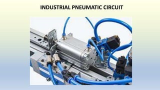
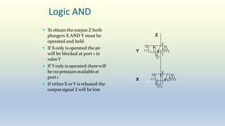
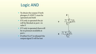
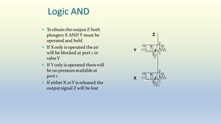
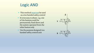
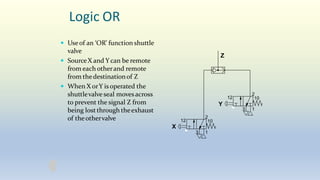
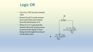
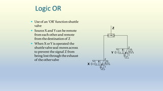
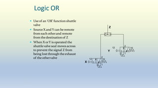
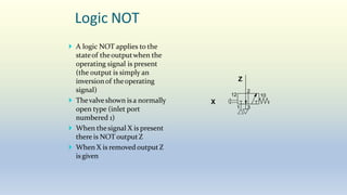
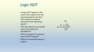
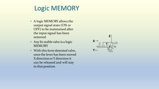
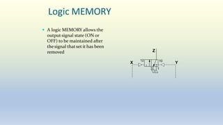
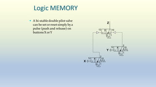
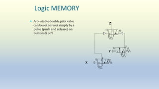
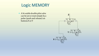
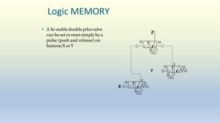
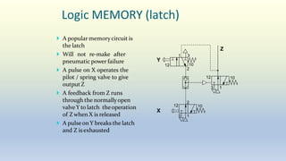
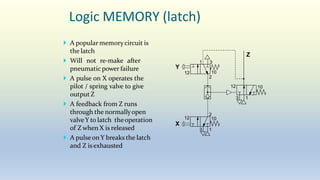
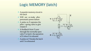
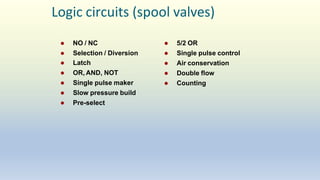
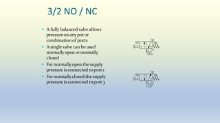
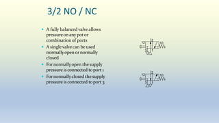
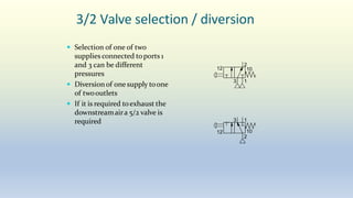
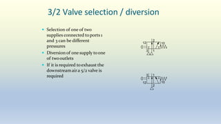
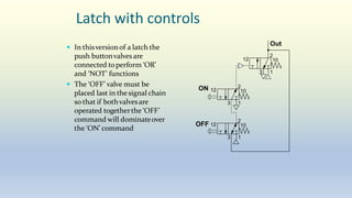
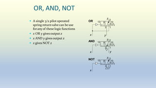
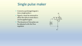
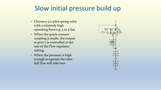
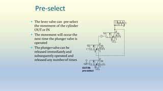
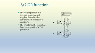
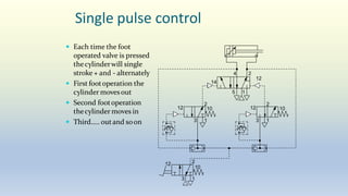
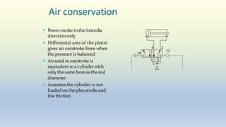
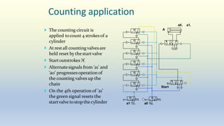
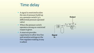
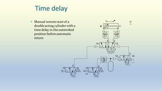
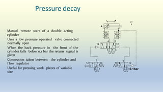
SlideShare a Scribd company logo
INDUSTRIAL PNEUMATIC CIRCUIT
Logic AND
 Toobtain theoutput Z both
plungers X AND Y must be
operated and held
 If X only isoperated theair
will be blocked at port 1 in
valveY
 If Yonly is operated therewill
be no pressureavailableat
port 1
 If eitherX orY is released the
outputsignal Z will be lost
2
3 1
12 10
2
3 1
12 10
X
Y
Z
Logic AND
 Toobtain theoutput Z both
plungers X AND Y must be
operated and held
 If X only isoperated theair
will be blocked at port 1 in
valveY
 If Yonly is operated therewill
be no pressureavailableat
port 1
 If eitherX orY is released the
outputsignal Z will be lost
2
3 1
12 10
2
3 1
X
Y
Z
12 10
Logic AND
 Toobtain theoutput Z both
plungers X AND Y must be
operated and held
 If X only isoperated theair
will be blocked at port 1 in
valveY
 If Yonly is operated therewill
be no pressureavailableat
port 1
 If eitherX orY is released the
outputsignal Z will be lost
2
3 1
12 10
2
3 1
12 10
X
Y
Z
Logic AND
 Toobtain theoutput Z both
plungers X AND Y must be
operated and held
 If X only isoperated theair
will be blocked at port 1 in
valveY
 If Yonly is operated therewill
be no pressureavailableat
port 1
 If eitherX orY is released the
outputsignal Z will be lost
2
3 1
2
3 1
12 10
X
Y
Z
12 10
Logic AND
 Toobtain theoutput Z both
plungers X AND Y must be
operated and held
 If X only isoperated theair
will be blocked at port 1 in
valveY
 If Yonly is operated therewill
be no pressureavailableat
port 1
 If eitherX orY is released the
outputsignal Z will be lost
2
3 1
2
3 1
X
Y
Z
12 10
12 10
Logic AND
 Toobtain theoutput Z both
plungers X AND Y must be
operated and held
 If X only isoperated theair
will be blocked at port 1 in
valveY
 If Yonly is operated therewill
be no pressureavailableat
port 1
 If eitherX orY is released the
outputsignal Z will be lost
2
3 1
2
3 1
12 10
X
Y
Z
12 10
Logic AND
 Toobtain theoutput Z both
plungers X AND Y must be
operated and held
 If X only isoperated theair
will be blocked at port 1 in
valveY
 If Yonly is operated therewill
be no pressureavailableat
port 1
 If eitherX orY is released the
outputsignal Z will be lost
2
3 1
12 10
2
3 1
12 10
X
Y
Z
Logic AND
 This method must not be used
as a two handed safetycontrol
 It is tooeasy toabuse. e.g. one
of the buttonscould be
permanently fixed down and
the system operated from the
other buttononly
 Use the purposedesigned two
handed safetycontrol unit
2
3 1
12 10
2
3 1
12 10
X
Y
Z
Logic OR
 Useof an ‘OR’ function shuttle
valve
 SourceX and Ycan be remote
from each otherand remote
from thedestinationof Z
 When X orY is operated the
shuttlevalve seal movesacross
to prevent the signal Z from
being lost through theexhaust
of theothervalve
Y
Z
2
3 1
12 10
2
X
3 1
12 10
Logic OR
 Useof an ‘OR’ function shuttle
valve
 SourceX and Ycan be remote
from each otherand remote
from thedestinationof Z
 When X orY is operated the
shuttlevalve seal movesacross
to prevent the signal Z from
being lost through theexhaust
of theothervalve
Y
Z
2
3 1
12 10
2
X
3 1
12 10
Logic OR
 Useof an ‘OR’ function shuttle
valve
 SourceX and Ycan be remote
from each otherand remote
from thedestinationof Z
 When X orY is operated the
shuttlevalve seal movesacross
to prevent the signal Z from
being lost through theexhaust
of theothervalve
Y
Z
2
3 1
12 10
2
X
3 1
12 10
Logic OR
 Useof an ‘OR’ function shuttle
valve
 SourceX and Ycan be remote
from each otherand remote
from thedestinationof Z
 When X orY is operated the
shuttlevalve seal movesacross
to prevent the signal Z from
being lost through theexhaust
of theothervalve
Y
Z
2
3 1
12 10
2
X
3 1
12 10
Logic OR
 Useof an ‘OR’ function shuttle
valve
 SourceX and Ycan be remote
from each otherand remote
from thedestinationof Z
 When X orY is operated the
shuttlevalve seal movesacross
to prevent the signal Z from
being lost through theexhaust
of theothervalve
Y
Z
2
3 1
12 10
2
X
3 1
12 10
Logic NOT
 A logic NOT applies to the
stateof theoutputwhen the
operating signal is present
(the output is simply an
inversionof theoperating
signal)
 Thevalve shown is a normally
open type (inlet port
numbered 1)
 When thesignal X is present
there is NOT outputZ
 When X is removed output Z
is given
2
1 3
12 10
Z
X
Logic MEMORY
 A logic MEMORYallows the
output signal state (ON or
OFF) to be maintained after
the input signal has been
removed
 Any bi-stablevalve is a logic
MEMORY
 With this leverdetented valve,
once the lever has been moved
X directionorYdirection it
can be released and will stay
in thatposition
Z
X
3 1
10
Y
12
Logic MEMORY
 A logic MEMORY allows the
output signal state (ON or
OFF) to be maintained after
thesignal thatset it has been
removed Z
X
3 1
12 10
Y
Logic MEMORY
 A bi-stabledoublepilotvalve
can be setorresetsimply bya
pulse (push and release) on
buttonsX orY
Z
3 1
2
Y
3 1
12 10
2
X
3 1
12 10
12 10
Logic MEMORY
 A bi-stabledoublepilotvalve
can be setorresetsimply bya
pulse (push and release) on
buttonsX orY
Z
3 1
2
Y
3 1
12 10
2
X
3 1
12 10
12 10
Logic MEMORY
 A bi-stabledoublepilotvalve
can be setorresetsimply bya
pulse (push and release) on
buttonsX orY
Z
3 1
2
Y
3 1
12 10
2
X
3 1
12 10
12 10
Logic MEMORY
 A bi-stabledoublepilotvalve
can be setorresetsimply bya
pulse (push and release) on
buttonsX orY
Z
3 1
2
Y
3 1
12 10
2
X
3 1
12 10
12 10
Logic MEMORY
 A bi-stabledoublepilotvalve
can be setorresetsimply bya
pulse (push and release) on
buttonsX orY
Z
3 1
2
Y
3 1
12 10
2
X
3 1
12 10
12 10
Logic MEMORY (latch)
 A popular memorycircuit is
the latch
 Will not re-make after
pneumaticpower failure
 A pulse on X operates the
pilot / spring valve to give
output Z
 A feedback from Z runs
through the normallyopen
valveY to latch theoperation
of Z when X is released
 A pulseon Y breaks the latch
and Z is exhausted
X
Y
Z
3 1
2
3 1
12 10
10
12
2
1 3
12 10
Logic MEMORY (latch)
 A popular memorycircuit is
the latch
 Will not re-make after
pneumaticpower failure
 A pulse on X operates the
pilot / spring valve to give
output Z
 A feedback from Z runs
through the normallyopen
valveY to latch theoperation
of Z when X is released
 A pulseon Y breaks the latch
and Z is exhausted
X
Y
Z
3 1
2
3 1
12 10
12 10
2
1 3
12 10
Logic MEMORY (latch)
 A popular memorycircuit is
the latch
 Will not re-make after
pneumaticpower failure
 A pulse on X operates the
pilot / spring valve to give
output Z
 A feedback from Z runs
through the normallyopen
valveY to latch theoperation
of Z when X is released
 A pulseon Y breaks the latch
and Z is exhausted
X
Y
Z
3 1
2
3 1
12 10
2
1 3
12 10
12 10
Logic circuits (spool valves)
 5/2 OR
 Single pulse control
 Air conservation
 Double flow
 Counting
 NO / NC
 Selection / Diversion
 Latch
 OR, AND, NOT
 Single pulse maker
 Slow pressure build
 Pre-select
3/2 NO / NC
 A fully balanced valveallows
pressureon any potor
combinationof ports
 A singlevalvecan be used
normallyopen or normally
closed
 For normallyopen thesupply
pressure is connected toport 1
 For normallyclosed the supply
pressure is connected toport 3
2
3 1
12 10
2
3 1
12 10
3/2 NO / NC
 A fully balanced valveallows
pressureon any potor
combinationof ports
 A singlevalvecan be used
normallyopen or normally
closed
 For normallyopen thesupply
pressure is connected toport 1
 For normallyclosed the supply
pressure is connected toport 3
2
3 1
12 10
2
3 1
12 10
3/2 Valve selection / diversion
 Selection of one of two
supplies connected toports 1
and 3 can be different
pressures
 Diversionof one supply toone
of twooutlets
 If it is required toexhaust the
downstreamaira 5/2 valve is
required
2
3 1
12 10
2
3 1
12 10
3/2 Valve selection / diversion
 Selection of one of two
supplies connected toports 1
and 3 can be different
pressures
 Diversionof one supply toone
of twooutlets
 If it is required toexhaust the
downstreamaira 5/2 valve is
required
2
3 1
2
3 1
12 10
12 10
Latch with controls
 In thisversionof a latch the
push buttonvalves are
connected toperform ‘OR’
and ‘NOT’ functions
 The ‘OFF’ valve must be
placed last in the signal chain
so that if bothvalvesare
operated togetherthe ‘OFF’
command will dominateover
the ‘ON’ command
2
3 1
12 10
2
3 1
10
2
3 1
10
ON 12
OFF 12
Out
OR, AND, NOT
 A single 3/2 pilot operated
spring returnvalvecan be use
foranyof these logic functions
 x OR y gives output z
 x AND y gives output z
 x gives NOT z
3 1
12 10
12 10
12 10
AND
OR
NOT
x y
z 2
x
3 1
y
z 2
3 1
x
z 2
Single pulse maker
 Convertsa prolonged signal x
intoa single pulse z
 Signal z must be removed to
allow thevalve to reset then x
can beapplied again
 Thedurationof the pulsecan
be adjusted with the flow
regulator
2
3 1
12 10
x
z
Slow initial pressure build up
 Choosea 3/2 pilotspring valve
with a relatively high
operating forcee.g. 3 to 4 bar
 When the quick connect
coupling is made, theoutput
at port 2 is controlled at the
rateof the f low regulator
setting
 When the pressure is high
enough tooperate thevalve
full flow will takeover
2
3 1
12 10
Pre-select
 The lever valve can pre-select
the movement of the cylinder
OUT or IN
 The movement will occur the
next time the plunger valve is
operated
 The plungervalvecan be
released immediatelyand
subsequently operated and
released any numberof times
2
3 1
12 10
2
3 1
12 10
2
3 1
12
10
OUT/IN
pre-select
5/2 OR function
 Thevalveat position ‘a’ is
reversed connected and
supplied from thevalve
conventionallyconnected at
position ‘b’
 Thecylindercan becontrolled
from either position ‘a’ ‘OR’
position ‘b’
1
2
4
5 3
14
12
2
4
5 1 3
14
12
a
b
Single pulse control
 Each time the foot
operated valve is pressed
thecylinderwill single
stroke + and - alternately
 First footoperation the
cylinder movesout
 Second footoperation
thecylinder moves in
 Third….. outand soon
2
4
14
12
2
3 1
12 10
5 1
12 10
2
3 1
3 1
12 2
10
Air conservation
 Powerstroke in the instroke
directiononly
 Differential area of the piston
gives an outstroke force when
the pressure is balanced
 Airused tooutstroke is
equivalent toacylinderwith
only thesame boreas the rod
diameter
 Assumes the cylinder is not
loaded on the plus strokeand
low friction
2
4
1
5
14
12
Double flow
 Wherea larger 3/2 valve is not
available
 Two f low paths in a 5/2 valve
each with a separate supply
can bearranged togivedouble
f loworsupply separate
devices
 Ensure the tube size to the
cylinder is large enough to
take thedouble flow
4 2
12
14
5 1 3
Double flow
 Wherea larger 3/2 valve is not
available
 Two f low paths in a 5/2 valve
each with a separate supply
can bearranged togivedouble
f loworsupply separate
devices
 Ensure the tube size to the
cylinder is large enough to
take thedouble flow
4 2
12
14
5 1 3
Counting
 Counting applications are
bestachieved with electro-
mechanical orprogrammable
electroniccounters
 Pneumaticcounting circuits
use large numbers of logic
valvesand can be slow
 Thecounting chain shown
will count to 4
 Red and blue are non-
overlapping alternatepulses,
purple is the reset line
2
1
3
4
Counting application
 The counting circuit is
applied tocount 4 strokesof a
cylinder
 At restall counting valves are
held reset by thestartvalve
 Startoutstrokes ‘A’
 Alternatesignals from ‘a1’ and
‘a0’ progressesoperation of
the counting valves up the
chain
 On the 4th operation of ‘a1’
the green signal resets the
startvalve tostop thecylinder
A
a0
a1
a0 a1
Start
Time delay
 A signal is restricted toslow
the rateof pressure build up
on a pressure switch (3/2
differential pressureoperated
valve)
 When the pressure switch
operates astrong un-restricted
output is given
 A reservoirprovides
capacitance toallow less fine
and sensitivesettingson the
f low regulatormaking iteasy
toadjust
1
2
3
12 10
Signal
in
Output
Time delay
 Manual remotestartof a
doubleacting cylinderwith a
timedelay in theoutstroked
position beforeautomatic
return
2
2
4
5 1 3
14 12
3 1
12 10
- +
A
a1
2
3 1
12 10
a1
1
3
12
2
10
Pressure decay
Manual remote start of a double acting
cylinder
Uses a low pressure operated valve connected
normally open
When the back pressure in the front of the
cylinder falls below 0.1 bar the return signal is
given
Connection taken between the cylinder and
f low regulator
Useful for pressing work pieces of variable
size
2
4
5 1 3
14 12
2
3 1
12 10
- +
A
a1
2
12
10
1 3 0.1bar
Electro-pneumatic
The majority of systems use electrical/electronic
control due to the high degree of sophistication
and flexibility
Solenoid valves are used to control cylinders
Feedback signals are from reed switches,
sensors and electrical limit switches
Logic is hard wired or programmed in to a
PLC (programmable logic controller)
a0 a1
2
4
14 12
5 1 3
A
 Circuit building block for
each cylinder
a0 a1

More Related Content

More from Dr.R. SELVAM

More from Dr.R. SELVAM (20)

3 capital structure
3 capital structure3 capital structure
3 capital structure
 
1 sources of finance
1 sources of finance1 sources of finance
1 sources of finance
 
2 term loan
2 term loan2 term loan
2 term loan
 
4 b. capital budgeting and cost analysis performance evaluation
4 b. capital budgeting and cost analysis   performance evaluation4 b. capital budgeting and cost analysis   performance evaluation
4 b. capital budgeting and cost analysis performance evaluation
 
4 a. capital budgeting and cost analysis
4 a. capital budgeting and cost analysis4 a. capital budgeting and cost analysis
4 a. capital budgeting and cost analysis
 
3 capital budgeting
3 capital budgeting3 capital budgeting
3 capital budgeting
 
2 working capital
2 working capital2 working capital
2 working capital
 
1 current assement management
1 current assement management1 current assement management
1 current assement management
 
2 b. project termination
2 b. project termination2 b. project termination
2 b. project termination
 
2 a. project auditing
2 a. project auditing2 a. project auditing
2 a. project auditing
 
1 b, evaluation of project
1 b, evaluation of project1 b, evaluation of project
1 b, evaluation of project
 
1 a, monitoring and evaluation of PM
1 a, monitoring and evaluation of PM1 a, monitoring and evaluation of PM
1 a, monitoring and evaluation of PM
 
3 industrial hydraulic circuits shapping, milling, drilling
3 industrial hydraulic circuits   shapping, milling, drilling3 industrial hydraulic circuits   shapping, milling, drilling
3 industrial hydraulic circuits shapping, milling, drilling
 
2 maintenance of hydraulic systems
2 maintenance of hydraulic systems2 maintenance of hydraulic systems
2 maintenance of hydraulic systems
 
1 hydraulic troubleshooting
1 hydraulic troubleshooting1 hydraulic troubleshooting
1 hydraulic troubleshooting
 
3 b. industrial pneumatic circuit advanced
3 b. industrial pneumatic circuit   advanced3 b. industrial pneumatic circuit   advanced
3 b. industrial pneumatic circuit advanced
 
3 a. industrial pneumatic circuit basic
3 a. industrial pneumatic circuit   basic3 a. industrial pneumatic circuit   basic
3 a. industrial pneumatic circuit basic
 
2 introduction to pneumatic systems
2 introduction to pneumatic systems2 introduction to pneumatic systems
2 introduction to pneumatic systems
 
1 b. pneumatic components
1 b. pneumatic components1 b. pneumatic components
1 b. pneumatic components
 
1 a. pneumatic introduction, gas laws
1 a. pneumatic   introduction, gas laws1 a. pneumatic   introduction, gas laws
1 a. pneumatic introduction, gas laws
 

Recently uploaded

Recently uploaded (20)

The Art Pastor's Guide to Sabbath | Steve Thomason
The Art Pastor's Guide to Sabbath | Steve ThomasonThe Art Pastor's Guide to Sabbath | Steve Thomason
The Art Pastor's Guide to Sabbath | Steve Thomason
 
aaaaaaaaaaaaaaaaaaaaaaaaaaaaaaaaaaaaaaaaa
aaaaaaaaaaaaaaaaaaaaaaaaaaaaaaaaaaaaaaaaaaaaaaaaaaaaaaaaaaaaaaaaaaaaaaaaaaaaaaaaaa
aaaaaaaaaaaaaaaaaaaaaaaaaaaaaaaaaaaaaaaaa
 
B.ed spl. HI pdusu exam paper-2023-24.pdf
B.ed spl. HI pdusu exam paper-2023-24.pdfB.ed spl. HI pdusu exam paper-2023-24.pdf
B.ed spl. HI pdusu exam paper-2023-24.pdf
 
Application of Matrices in real life. Presentation on application of matrices
Application of Matrices in real life. Presentation on application of matricesApplication of Matrices in real life. Presentation on application of matrices
Application of Matrices in real life. Presentation on application of matrices
 
Benefits and Challenges of Using Open Educational Resources
Benefits and Challenges of Using Open Educational ResourcesBenefits and Challenges of Using Open Educational Resources
Benefits and Challenges of Using Open Educational Resources
 
Morse OER Some Benefits and Challenges.pptx
Morse OER Some Benefits and Challenges.pptxMorse OER Some Benefits and Challenges.pptx
Morse OER Some Benefits and Challenges.pptx
 
Keeping Your Information Safe with Centralized Security Services
Keeping Your Information Safe with Centralized Security ServicesKeeping Your Information Safe with Centralized Security Services
Keeping Your Information Safe with Centralized Security Services
 
aaaaaaaaaaaaaaaaaaaaaaaaaaaaaaaaaaaaaaaaaaaaaaaaaaaaaaa
aaaaaaaaaaaaaaaaaaaaaaaaaaaaaaaaaaaaaaaaaaaaaaaaaaaaaaaaaaaaaaaaaaaaaaaaaaaaaaaaaaaaaaaaaaaaaaaaaaaaaaaaaaaaaa
aaaaaaaaaaaaaaaaaaaaaaaaaaaaaaaaaaaaaaaaaaaaaaaaaaaaaaa
 
Basic phrases for greeting and assisting costumers
Basic phrases for greeting and assisting costumersBasic phrases for greeting and assisting costumers
Basic phrases for greeting and assisting costumers
 
UNIT – IV_PCI Complaints: Complaints and evaluation of complaints, Handling o...
UNIT – IV_PCI Complaints: Complaints and evaluation of complaints, Handling o...UNIT – IV_PCI Complaints: Complaints and evaluation of complaints, Handling o...
UNIT – IV_PCI Complaints: Complaints and evaluation of complaints, Handling o...
 
2024_Student Session 2_ Set Plan Preparation.pptx
2024_Student Session 2_ Set Plan Preparation.pptx2024_Student Session 2_ Set Plan Preparation.pptx
2024_Student Session 2_ Set Plan Preparation.pptx
 
How to Create Map Views in the Odoo 17 ERP
How to Create Map Views in the Odoo 17 ERPHow to Create Map Views in the Odoo 17 ERP
How to Create Map Views in the Odoo 17 ERP
 
Matatag-Curriculum and the 21st Century Skills Presentation.pptx
Matatag-Curriculum and the 21st Century Skills Presentation.pptxMatatag-Curriculum and the 21st Century Skills Presentation.pptx
Matatag-Curriculum and the 21st Century Skills Presentation.pptx
 
Gyanartha SciBizTech Quiz slideshare.pptx
Gyanartha SciBizTech Quiz slideshare.pptxGyanartha SciBizTech Quiz slideshare.pptx
Gyanartha SciBizTech Quiz slideshare.pptx
 
Operations Management - Book1.p - Dr. Abdulfatah A. Salem
Operations Management - Book1.p  - Dr. Abdulfatah A. SalemOperations Management - Book1.p  - Dr. Abdulfatah A. Salem
Operations Management - Book1.p - Dr. Abdulfatah A. Salem
 
Jose-Rizal-and-Philippine-Nationalism-National-Symbol-2.pptx
Jose-Rizal-and-Philippine-Nationalism-National-Symbol-2.pptxJose-Rizal-and-Philippine-Nationalism-National-Symbol-2.pptx
Jose-Rizal-and-Philippine-Nationalism-National-Symbol-2.pptx
 
size separation d pharm 1st year pharmaceutics
size separation d pharm 1st year pharmaceuticssize separation d pharm 1st year pharmaceutics
size separation d pharm 1st year pharmaceutics
 
Sectors of the Indian Economy - Class 10 Study Notes pdf
Sectors of the Indian Economy - Class 10 Study Notes pdfSectors of the Indian Economy - Class 10 Study Notes pdf
Sectors of the Indian Economy - Class 10 Study Notes pdf
 
Salient features of Environment protection Act 1986.pptx
Salient features of Environment protection Act 1986.pptxSalient features of Environment protection Act 1986.pptx
Salient features of Environment protection Act 1986.pptx
 
The impact of social media on mental health and well-being has been a topic o...
The impact of social media on mental health and well-being has been a topic o...The impact of social media on mental health and well-being has been a topic o...
The impact of social media on mental health and well-being has been a topic o...
 

3 c. industrial pneumatic circuit logic

  • 2.
  • 3. Logic AND  Toobtain theoutput Z both plungers X AND Y must be operated and held  If X only isoperated theair will be blocked at port 1 in valveY  If Yonly is operated therewill be no pressureavailableat port 1  If eitherX orY is released the outputsignal Z will be lost 2 3 1 12 10 2 3 1 12 10 X Y Z
  • 4. Logic AND  Toobtain theoutput Z both plungers X AND Y must be operated and held  If X only isoperated theair will be blocked at port 1 in valveY  If Yonly is operated therewill be no pressureavailableat port 1  If eitherX orY is released the outputsignal Z will be lost 2 3 1 12 10 2 3 1 X Y Z 12 10
  • 5. Logic AND  Toobtain theoutput Z both plungers X AND Y must be operated and held  If X only isoperated theair will be blocked at port 1 in valveY  If Yonly is operated therewill be no pressureavailableat port 1  If eitherX orY is released the outputsignal Z will be lost 2 3 1 12 10 2 3 1 12 10 X Y Z
  • 6. Logic AND  Toobtain theoutput Z both plungers X AND Y must be operated and held  If X only isoperated theair will be blocked at port 1 in valveY  If Yonly is operated therewill be no pressureavailableat port 1  If eitherX orY is released the outputsignal Z will be lost 2 3 1 2 3 1 12 10 X Y Z 12 10
  • 7. Logic AND  Toobtain theoutput Z both plungers X AND Y must be operated and held  If X only isoperated theair will be blocked at port 1 in valveY  If Yonly is operated therewill be no pressureavailableat port 1  If eitherX orY is released the outputsignal Z will be lost 2 3 1 2 3 1 X Y Z 12 10 12 10
  • 8. Logic AND  Toobtain theoutput Z both plungers X AND Y must be operated and held  If X only isoperated theair will be blocked at port 1 in valveY  If Yonly is operated therewill be no pressureavailableat port 1  If eitherX orY is released the outputsignal Z will be lost 2 3 1 2 3 1 12 10 X Y Z 12 10
  • 9. Logic AND  Toobtain theoutput Z both plungers X AND Y must be operated and held  If X only isoperated theair will be blocked at port 1 in valveY  If Yonly is operated therewill be no pressureavailableat port 1  If eitherX orY is released the outputsignal Z will be lost 2 3 1 12 10 2 3 1 12 10 X Y Z
  • 10. Logic AND  This method must not be used as a two handed safetycontrol  It is tooeasy toabuse. e.g. one of the buttonscould be permanently fixed down and the system operated from the other buttononly  Use the purposedesigned two handed safetycontrol unit 2 3 1 12 10 2 3 1 12 10 X Y Z
  • 11. Logic OR  Useof an ‘OR’ function shuttle valve  SourceX and Ycan be remote from each otherand remote from thedestinationof Z  When X orY is operated the shuttlevalve seal movesacross to prevent the signal Z from being lost through theexhaust of theothervalve Y Z 2 3 1 12 10 2 X 3 1 12 10
  • 12. Logic OR  Useof an ‘OR’ function shuttle valve  SourceX and Ycan be remote from each otherand remote from thedestinationof Z  When X orY is operated the shuttlevalve seal movesacross to prevent the signal Z from being lost through theexhaust of theothervalve Y Z 2 3 1 12 10 2 X 3 1 12 10
  • 13. Logic OR  Useof an ‘OR’ function shuttle valve  SourceX and Ycan be remote from each otherand remote from thedestinationof Z  When X orY is operated the shuttlevalve seal movesacross to prevent the signal Z from being lost through theexhaust of theothervalve Y Z 2 3 1 12 10 2 X 3 1 12 10
  • 14. Logic OR  Useof an ‘OR’ function shuttle valve  SourceX and Ycan be remote from each otherand remote from thedestinationof Z  When X orY is operated the shuttlevalve seal movesacross to prevent the signal Z from being lost through theexhaust of theothervalve Y Z 2 3 1 12 10 2 X 3 1 12 10
  • 15. Logic OR  Useof an ‘OR’ function shuttle valve  SourceX and Ycan be remote from each otherand remote from thedestinationof Z  When X orY is operated the shuttlevalve seal movesacross to prevent the signal Z from being lost through theexhaust of theothervalve Y Z 2 3 1 12 10 2 X 3 1 12 10
  • 16. Logic NOT  A logic NOT applies to the stateof theoutputwhen the operating signal is present (the output is simply an inversionof theoperating signal)  Thevalve shown is a normally open type (inlet port numbered 1)  When thesignal X is present there is NOT outputZ  When X is removed output Z is given 2 1 3 12 10 Z X
  • 17. Logic NOT  A logic NOT applies to the stateof theoutputwhen the operating signal is present (the output is simply an inversionof theoperating signal)  Thevalve shown is a normally open type (inlet port numbered 1)  When thesignal X is present there is NOT outputZ  When X is removed output Z is given 2 1 3 12 10 Z X
  • 18. Logic NOT  A logic NOT applies to the stateof theoutputwhen the operating signal is present (the output is simply an inversionof theoperating signal)  Thevalve shown is a normally open type (inlet port numbered 1)  When thesignal X is present there is NOT outputZ  When X is removed output Z is given 2 1 3 12 10 Z X
  • 19. Logic MEMORY  A logic MEMORYallows the output signal state (ON or OFF) to be maintained after the input signal has been removed  Any bi-stablevalve is a logic MEMORY  With this leverdetented valve, once the lever has been moved X directionorYdirection it can be released and will stay in thatposition Z X 3 1 10 Y 12
  • 20. Logic MEMORY  A logic MEMORY allows the output signal state (ON or OFF) to be maintained after thesignal thatset it has been removed Z X 3 1 12 10 Y
  • 21. Logic MEMORY  A bi-stabledoublepilotvalve can be setorresetsimply bya pulse (push and release) on buttonsX orY Z 3 1 2 Y 3 1 12 10 2 X 3 1 12 10 12 10
  • 22. Logic MEMORY  A bi-stabledoublepilotvalve can be setorresetsimply bya pulse (push and release) on buttonsX orY Z 3 1 2 Y 3 1 12 10 2 X 3 1 12 10 12 10
  • 23. Logic MEMORY  A bi-stabledoublepilotvalve can be setorresetsimply bya pulse (push and release) on buttonsX orY Z 3 1 2 Y 3 1 12 10 2 X 3 1 12 10 12 10
  • 24. Logic MEMORY  A bi-stabledoublepilotvalve can be setorresetsimply bya pulse (push and release) on buttonsX orY Z 3 1 2 Y 3 1 12 10 2 X 3 1 12 10 12 10
  • 25. Logic MEMORY  A bi-stabledoublepilotvalve can be setorresetsimply bya pulse (push and release) on buttonsX orY Z 3 1 2 Y 3 1 12 10 2 X 3 1 12 10 12 10
  • 26. Logic MEMORY (latch)  A popular memorycircuit is the latch  Will not re-make after pneumaticpower failure  A pulse on X operates the pilot / spring valve to give output Z  A feedback from Z runs through the normallyopen valveY to latch theoperation of Z when X is released  A pulseon Y breaks the latch and Z is exhausted X Y Z 3 1 2 3 1 12 10 10 12 2 1 3 12 10
  • 27. Logic MEMORY (latch)  A popular memorycircuit is the latch  Will not re-make after pneumaticpower failure  A pulse on X operates the pilot / spring valve to give output Z  A feedback from Z runs through the normallyopen valveY to latch theoperation of Z when X is released  A pulseon Y breaks the latch and Z is exhausted X Y Z 3 1 2 3 1 12 10 12 10 2 1 3 12 10
  • 28. Logic MEMORY (latch)  A popular memorycircuit is the latch  Will not re-make after pneumaticpower failure  A pulse on X operates the pilot / spring valve to give output Z  A feedback from Z runs through the normallyopen valveY to latch theoperation of Z when X is released  A pulseon Y breaks the latch and Z is exhausted X Y Z 3 1 2 3 1 12 10 12 10 2 1 3 12 10
  • 29. Logic MEMORY (latch)  A popular memorycircuit is the latch  Will not re-make after pneumaticpower failure  A pulse on X operates the pilot / spring valve to give output Z  A feedback from Z runs through the normallyopen valveY to latch theoperation of Z when X is released  A pulseon Y breaks the latch and Z is exhausted X Y Z 3 1 2 3 1 12 10 2 1 3 12 10 12 10
  • 30. Logic MEMORY (latch)  A popular memorycircuit is the latch  Will not re-make after pneumaticpower failure  A pulse on X operates the pilot / spring valve to give output Z  A feedback from Z runs through the normallyopen valveY to latch theoperation of Z when X is released  A pulseon Y breaks the latch and Z is exhausted X Y Z 3 1 2 3 1 12 10 2 1 3 12 10 12 10
  • 31.
  • 32. Logic circuits (spool valves)  5/2 OR  Single pulse control  Air conservation  Double flow  Counting  NO / NC  Selection / Diversion  Latch  OR, AND, NOT  Single pulse maker  Slow pressure build  Pre-select
  • 33. 3/2 NO / NC  A fully balanced valveallows pressureon any potor combinationof ports  A singlevalvecan be used normallyopen or normally closed  For normallyopen thesupply pressure is connected toport 1  For normallyclosed the supply pressure is connected toport 3 2 3 1 12 10 2 3 1 12 10
  • 34. 3/2 NO / NC  A fully balanced valveallows pressureon any potor combinationof ports  A singlevalvecan be used normallyopen or normally closed  For normallyopen thesupply pressure is connected toport 1  For normallyclosed the supply pressure is connected toport 3 2 3 1 12 10 2 3 1 12 10
  • 35. 3/2 Valve selection / diversion  Selection of one of two supplies connected toports 1 and 3 can be different pressures  Diversionof one supply toone of twooutlets  If it is required toexhaust the downstreamaira 5/2 valve is required 2 3 1 12 10 2 3 1 12 10
  • 36. 3/2 Valve selection / diversion  Selection of one of two supplies connected toports 1 and 3 can be different pressures  Diversionof one supply toone of twooutlets  If it is required toexhaust the downstreamaira 5/2 valve is required 2 3 1 2 3 1 12 10 12 10
  • 37. Latch with controls  In thisversionof a latch the push buttonvalves are connected toperform ‘OR’ and ‘NOT’ functions  The ‘OFF’ valve must be placed last in the signal chain so that if bothvalvesare operated togetherthe ‘OFF’ command will dominateover the ‘ON’ command 2 3 1 12 10 2 3 1 10 2 3 1 10 ON 12 OFF 12 Out
  • 38. OR, AND, NOT  A single 3/2 pilot operated spring returnvalvecan be use foranyof these logic functions  x OR y gives output z  x AND y gives output z  x gives NOT z 3 1 12 10 12 10 12 10 AND OR NOT x y z 2 x 3 1 y z 2 3 1 x z 2
  • 39. Single pulse maker  Convertsa prolonged signal x intoa single pulse z  Signal z must be removed to allow thevalve to reset then x can beapplied again  Thedurationof the pulsecan be adjusted with the flow regulator 2 3 1 12 10 x z
  • 40. Slow initial pressure build up  Choosea 3/2 pilotspring valve with a relatively high operating forcee.g. 3 to 4 bar  When the quick connect coupling is made, theoutput at port 2 is controlled at the rateof the f low regulator setting  When the pressure is high enough tooperate thevalve full flow will takeover 2 3 1 12 10
  • 41. Pre-select  The lever valve can pre-select the movement of the cylinder OUT or IN  The movement will occur the next time the plunger valve is operated  The plungervalvecan be released immediatelyand subsequently operated and released any numberof times 2 3 1 12 10 2 3 1 12 10 2 3 1 12 10 OUT/IN pre-select
  • 42. 5/2 OR function  Thevalveat position ‘a’ is reversed connected and supplied from thevalve conventionallyconnected at position ‘b’  Thecylindercan becontrolled from either position ‘a’ ‘OR’ position ‘b’ 1 2 4 5 3 14 12 2 4 5 1 3 14 12 a b
  • 43. Single pulse control  Each time the foot operated valve is pressed thecylinderwill single stroke + and - alternately  First footoperation the cylinder movesout  Second footoperation thecylinder moves in  Third….. outand soon 2 4 14 12 2 3 1 12 10 5 1 12 10 2 3 1 3 1 12 2 10
  • 44. Air conservation  Powerstroke in the instroke directiononly  Differential area of the piston gives an outstroke force when the pressure is balanced  Airused tooutstroke is equivalent toacylinderwith only thesame boreas the rod diameter  Assumes the cylinder is not loaded on the plus strokeand low friction 2 4 1 5 14 12
  • 45. Air conservation  Powerstroke in the instroke directiononly  Differential area of the piston gives an outstroke force when the pressure is balanced  Airused tooutstroke is equivalent toacylinderwith only thesame boreas the rod diameter  Assumes the cylinder is not loaded on the plus strokeand low friction 2 4 1 5 14 12
  • 46. Double flow  Wherea larger 3/2 valve is not available  Two f low paths in a 5/2 valve each with a separate supply can bearranged togivedouble f loworsupply separate devices  Ensure the tube size to the cylinder is large enough to take thedouble flow 4 2 12 14 5 1 3
  • 47. Double flow  Wherea larger 3/2 valve is not available  Two f low paths in a 5/2 valve each with a separate supply can bearranged togivedouble f loworsupply separate devices  Ensure the tube size to the cylinder is large enough to take thedouble flow 4 2 12 14 5 1 3
  • 48. Counting  Counting applications are bestachieved with electro- mechanical orprogrammable electroniccounters  Pneumaticcounting circuits use large numbers of logic valvesand can be slow  Thecounting chain shown will count to 4  Red and blue are non- overlapping alternatepulses, purple is the reset line 2 1 3 4
  • 49. Counting application  The counting circuit is applied tocount 4 strokesof a cylinder  At restall counting valves are held reset by thestartvalve  Startoutstrokes ‘A’  Alternatesignals from ‘a1’ and ‘a0’ progressesoperation of the counting valves up the chain  On the 4th operation of ‘a1’ the green signal resets the startvalve tostop thecylinder A a0 a1 a0 a1 Start
  • 50.
  • 51. Time delay  A signal is restricted toslow the rateof pressure build up on a pressure switch (3/2 differential pressureoperated valve)  When the pressure switch operates astrong un-restricted output is given  A reservoirprovides capacitance toallow less fine and sensitivesettingson the f low regulatormaking iteasy toadjust 1 2 3 12 10 Signal in Output
  • 52. Time delay  Manual remotestartof a doubleacting cylinderwith a timedelay in theoutstroked position beforeautomatic return 2 2 4 5 1 3 14 12 3 1 12 10 - + A a1 2 3 1 12 10 a1 1 3 12 2 10
  • 53. Pressure decay Manual remote start of a double acting cylinder Uses a low pressure operated valve connected normally open When the back pressure in the front of the cylinder falls below 0.1 bar the return signal is given Connection taken between the cylinder and f low regulator Useful for pressing work pieces of variable size 2 4 5 1 3 14 12 2 3 1 12 10 - + A a1 2 12 10 1 3 0.1bar
  • 54. Electro-pneumatic The majority of systems use electrical/electronic control due to the high degree of sophistication and flexibility Solenoid valves are used to control cylinders Feedback signals are from reed switches, sensors and electrical limit switches Logic is hard wired or programmed in to a PLC (programmable logic controller) a0 a1 2 4 14 12 5 1 3 A  Circuit building block for each cylinder a0 a1