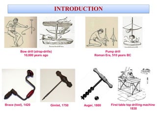
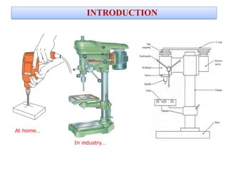
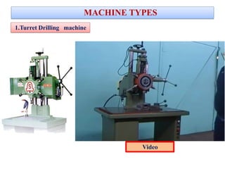
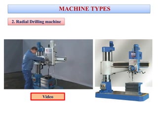
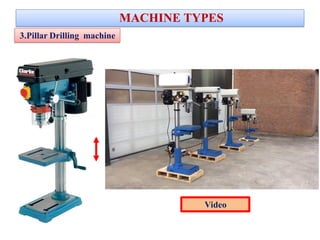
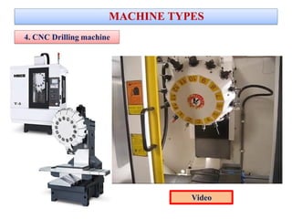
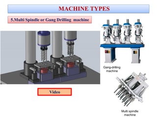
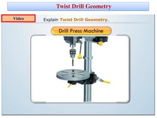
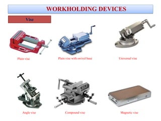
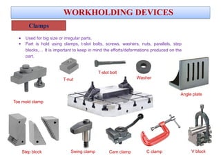
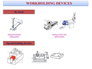
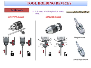
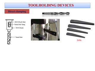
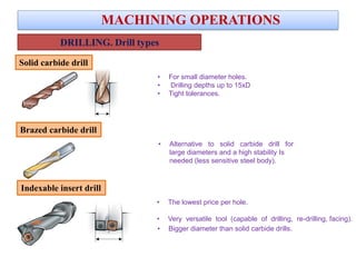
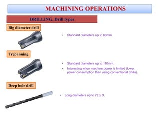
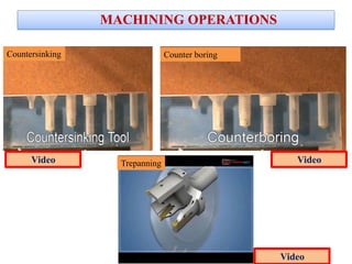
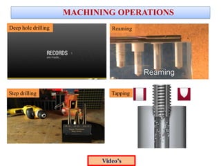
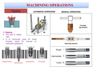
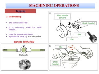
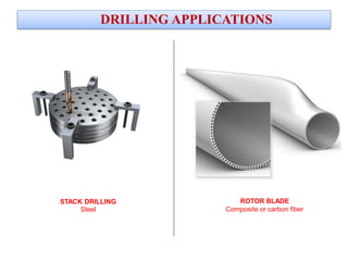
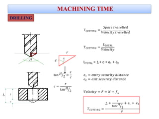
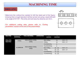
Drilling
• Drilling covers the methods of making cylindrical holes in a workpiece with metal cutting tools.
• The machine tool is called a drill.
• Typical operations: trepanning, counterboring, countersinking, reaming, boring, and
tapping,,…
• Common to all these processes is a main rotating movement combined with a linear
feed.
• Demands on chipbreaking and the evacuation of chips is critical in drilling.
Drilling- Introduction
INTRODUCTION
Brace (tool), 1420
Bow drill (strap-drills)
10,000 years ago
First table top drilling machine
1838
Pump drill
Roman Era, 510 years BC
Gimlet, 1750 Auger, 1800
INTRODUCTION
At home…
In industry…
VIDEO
MACHINE TYPES
1.Turret Drilling machine
MACHINE TYPES
VIDO
Video
MACHINE TYPES
2. Radial Drilling machine
Video
3.Pillar Drilling machine
MACHINE TYPES
Video
4. CNC Drilling machine
MACHINE TYPES
VIDEO Video
MACHINE TYPES
5.Multi Spindle or Gang Drilling machine
Gang-drilling
machine
Multi spindle
machine
VIDEO
Video
Twist Drill Geometry
Video
WORK HOLDING DEVICES
Plain vise Plain vise with swivel base Universal vise
Angle vise Compound vise
WORKHOLDING DEVICES
Vise
Magnetic vise
Clamps
• Used for big size or irregular parts.
• Part is hold using clamps, t-slot bolts, screws, washers, nuts, parallels, step
blocks,… It is important to keep in mind the efforts/deformations produced on the
part.
WORKHOLDING DEVICES
Step block
Angle plate
Toe mold clamp
Cam clamp
Washer
C clamp V blockSwing clamp
T-nut
T-slot bolt
WORKHOLDING DEVICES
By hand
Using the hands
(long parts)
Using a hand vise
(short parts)
Special holding devices
TOOL HOLDING DEVICES
Drill chuck
KEY TYPE CHUCK KEYLESS CHUCK
TOOL HOLDING DEVICES
Morse Taper Shank
Straight Shank
• It is used to hold cylindrical shank
drills.
Drill sleeve
TOOLHOLDING DEVICES
• It is used to hold tapered shank drills.
• For too SMALL drills for the tapered hole in the spindle.
Drill socket
• It is used to hold tapered shank drills.
• For too LARGE drills for the tapered hole in the spindle.
Direct clamping
TOOLHOLDING DEVICES
Drifts
MACHINING OPERATIONS
• The lowest price per hole.
• Very versatile tool (capable of drilling, re-drilling, facing).
• Bigger diameter than solid carbide drills.
MACHINING OPERATIONS
DRILLING. Drill types
Indexable insert drill
Brazed carbide drill
• For small diameter holes.
• Drilling depths up to 15xD
• Tight tolerances.
• Alternative to solid carbide drill for
large diameters and a high stability Is
needed (less sensitive steel body).
Solid carbide drill
MACHINING OPERATIONS
• Standard diameters up to 110mm.
• Interesting when machine power is limited (lower
power consumption than using conventional driills).
• Long diameters up to 72 x D.
DRILLING. Drill types
• Standard diameters up to 80mm.
Trepanning
Deep hole drill
VIDEO
Big diameter drill
5xD
MACHINING OPERATIONS
10xD
Dc
15xD
L/Dc
Solid carbide drill
Deep hole drilling
10 20 30 40 50 60 70 80 110
Trepanning
Small
length drill
Brazed
carbide drill
Big diameter
drill
DRILLING. Drill types
Counter boring
DRILLING. Machining operations
MACHINING OPERATIONS
Reaming
Counter sinking
TappingCenter drilling
Spot facing
Tapered drilling
Redrilling
Step drilling
Drilling
Deep hole drilling
Trepanning
MACHINING OPERATIONS
Countersinking Counter boring
Trepanning
Video
VideoVideo
MACHINING OPERATIONS
Deep hole drilling Reaming
Step drilling Tapping
Video’s
It is the most common drilling
operation, where a hole is drilled
in solid material.
Through hole Blind hole
SPOT DRILLING
• The purpose of spot drilling is to drill a hole that will act as
a guide for drilling the final hole.
• Used in milling and drilling machines.
CENTER DRILLING
• The purpose of center drilling is to drill a hole that will act
as a center of rotation for possible following operations.
• Used in turning machines.
VIDEO
MACHINING OPERATIONS
VIDEO
Spot drilling / Center drilling
Drilling
Trepanning
MACHINING OPERATIONS
• Trepanning is commonly used for creating larger diameter holes
(up to 1.000 mm) where a standard drill bit is not feasible or
economical.
• The trepanning tool does not machine the whole diameter, only a
ring at the periphery.
• In horizontal set-ups, long and heavy cores may require a core
support to prevent the core from falling down (not in vertical).
• This method is for through-hole applications.
Redrilling or boring
• It consists on increasing the hole size.
Video
Counterboring
Countersinking
MACHINING OPERATIONS
The tool is called “counterbore”, and it has a pilot to
guide the cutting action.
It is commonly used for:
• enlarging a hole to make a bolt head fit flush with
the surface.
• spot facing in workpieces that are forged or
casted.
IDEO
• This process is similar to counterboring, but the step in the hole is
cone- shaped.
• The tool is called “countersink”.
A common use is:
• to allow the head of a countersunk bolt or screw, when placed in
the hole,
• to sit flush with or below the surface of the surrounding material.
• to remove the burr left from a previous drilling or tapping
operation.
• to enhance pin entry.
VIDEO VIDEO
a) Manual reamers: long entry (A)
and length (L)
Milling reamers: short entry (A)
and length (L)
Reamer with no shank
or separated shank.
b)
c)
VIDEO
MACHINING OPERATIONS
The reamer never should be
spinned counterclockwise.
Reaming
Straight flute
Axial coolant supply
For blind holes
Spiral flute
Lateral coolant supply
For through holes
RIGHT WRONG
• Objective: To achive a good surface roughness and
good dimensional tolerances (H7) in a pre-drilled
hole.
• High penetration rates and small depths of cut.
• The tool is called “reamer”.
Taper drilling
MACHINING OPERATIONS
• Taper drills were engineered to be used to pre drill the pilot holes for
the shank and threaded portion of a wood screw.
Step drilling
• The tool is called “step drill”.
• The transition between this ground diameter and the original
diameter is either straight, to form a counterbore, or angled, to form
a countersink.
• These drills are limited to use on thin material (e.g. sheet-metal
work).
• Improves production times, reduces number of
drills.
VIDEO
• The tool is called
“tap”.
• It is commonly used for small
threads. Used for manual or
automatic operations.
Straight flute tap
Spiral point tap
Spiral flute tap Forming tap
Tapping
MACHINING OPERATIONS
1- Tapping:
Rough
Intermediate
Finish
MANUAL OPERATION
Hand tap wrench
T-handle
tap wrench
AUTOMATIC OPERATION
• The tool is called “die”.
• It is commonly used for small
threads.
• Used for manual operations.
• a)Within the lathe. b) In a bench vise.
Main spindle
(chuck)
Part
Die
Stock (handle)
VIDEO
2- Die threading:
b)
a)
Die
Stock
(handle)
MACHINING OPERATIONS
Die handle
Tapping
MANUAL OPERATION
DRILLING APPLICATIONS
STACK DRILLING
Steel
DRILLING APPLICATIONS
ROTOR BLADE
Composite or carbon fiber
MACHINING TIME
MACHINING TIME
H
H
2c
r
L
L
Tc
L
·nn...................................................
Va
........................................................................................L
l
c
L
DRILLING
MACHINING TIME
Determine the cutting time needed to drill the steel part of the figure,
knowing that a rough operation will be carried out using a twist drill with
a tip angle of H=118°. The entry and exit security distance are 3mm.
For additional cutting data, please refer to “Cutting
parameters” section at the end of this presentation.
DRILLING
MACHINE
WORKPIECE
TOOL MATERIAL OPERATION
Vc fn
MATERIAL (m/min) (mm/rev)
DRILLING
MACHINE
STEEL
HIGH SPEED STEEL
(HSS)
ALUMINIUM
HIGH SPEED STEEL
(HSS)
Spot drilling 18 0.04 – 0.1
Drilling 18 0.04 – 0.1
Counterboring 9
Countersinking 9
Spot drilling 30 – 40 0.04 – 0.1
Drilling 30 – 40 0.04 – 0.1
Counterboring 15 – 20
Countersinking 15 – 20

08 drilling

  • 1.
  • 2.
    • Drilling coversthe methods of making cylindrical holes in a workpiece with metal cutting tools. • The machine tool is called a drill. • Typical operations: trepanning, counterboring, countersinking, reaming, boring, and tapping,,… • Common to all these processes is a main rotating movement combined with a linear feed. • Demands on chipbreaking and the evacuation of chips is critical in drilling. Drilling- Introduction
  • 3.
    INTRODUCTION Brace (tool), 1420 Bowdrill (strap-drills) 10,000 years ago First table top drilling machine 1838 Pump drill Roman Era, 510 years BC Gimlet, 1750 Auger, 1800
  • 4.
  • 5.
  • 6.
  • 7.
    MACHINE TYPES 2. RadialDrilling machine Video
  • 8.
  • 9.
    4. CNC Drillingmachine MACHINE TYPES VIDEO Video
  • 10.
    MACHINE TYPES 5.Multi Spindleor Gang Drilling machine Gang-drilling machine Multi spindle machine VIDEO Video
  • 11.
  • 12.
  • 13.
    Plain vise Plainvise with swivel base Universal vise Angle vise Compound vise WORKHOLDING DEVICES Vise Magnetic vise
  • 14.
    Clamps • Used forbig size or irregular parts. • Part is hold using clamps, t-slot bolts, screws, washers, nuts, parallels, step blocks,… It is important to keep in mind the efforts/deformations produced on the part. WORKHOLDING DEVICES Step block Angle plate Toe mold clamp Cam clamp Washer C clamp V blockSwing clamp T-nut T-slot bolt
  • 15.
    WORKHOLDING DEVICES By hand Usingthe hands (long parts) Using a hand vise (short parts) Special holding devices
  • 16.
  • 17.
    Drill chuck KEY TYPECHUCK KEYLESS CHUCK TOOL HOLDING DEVICES Morse Taper Shank Straight Shank • It is used to hold cylindrical shank drills.
  • 18.
    Drill sleeve TOOLHOLDING DEVICES •It is used to hold tapered shank drills. • For too SMALL drills for the tapered hole in the spindle. Drill socket • It is used to hold tapered shank drills. • For too LARGE drills for the tapered hole in the spindle.
  • 19.
  • 20.
  • 21.
    • The lowestprice per hole. • Very versatile tool (capable of drilling, re-drilling, facing). • Bigger diameter than solid carbide drills. MACHINING OPERATIONS DRILLING. Drill types Indexable insert drill Brazed carbide drill • For small diameter holes. • Drilling depths up to 15xD • Tight tolerances. • Alternative to solid carbide drill for large diameters and a high stability Is needed (less sensitive steel body). Solid carbide drill
  • 22.
    MACHINING OPERATIONS • Standarddiameters up to 110mm. • Interesting when machine power is limited (lower power consumption than using conventional driills). • Long diameters up to 72 x D. DRILLING. Drill types • Standard diameters up to 80mm. Trepanning Deep hole drill VIDEO Big diameter drill
  • 23.
    5xD MACHINING OPERATIONS 10xD Dc 15xD L/Dc Solid carbidedrill Deep hole drilling 10 20 30 40 50 60 70 80 110 Trepanning Small length drill Brazed carbide drill Big diameter drill DRILLING. Drill types
  • 24.
    Counter boring DRILLING. Machiningoperations MACHINING OPERATIONS Reaming Counter sinking TappingCenter drilling Spot facing Tapered drilling Redrilling Step drilling Drilling Deep hole drilling Trepanning
  • 25.
    MACHINING OPERATIONS Countersinking Counterboring Trepanning Video VideoVideo
  • 26.
    MACHINING OPERATIONS Deep holedrilling Reaming Step drilling Tapping Video’s
  • 27.
    It is themost common drilling operation, where a hole is drilled in solid material. Through hole Blind hole SPOT DRILLING • The purpose of spot drilling is to drill a hole that will act as a guide for drilling the final hole. • Used in milling and drilling machines. CENTER DRILLING • The purpose of center drilling is to drill a hole that will act as a center of rotation for possible following operations. • Used in turning machines. VIDEO MACHINING OPERATIONS VIDEO Spot drilling / Center drilling Drilling
  • 28.
    Trepanning MACHINING OPERATIONS • Trepanningis commonly used for creating larger diameter holes (up to 1.000 mm) where a standard drill bit is not feasible or economical. • The trepanning tool does not machine the whole diameter, only a ring at the periphery. • In horizontal set-ups, long and heavy cores may require a core support to prevent the core from falling down (not in vertical). • This method is for through-hole applications. Redrilling or boring • It consists on increasing the hole size. Video
  • 29.
    Counterboring Countersinking MACHINING OPERATIONS The toolis called “counterbore”, and it has a pilot to guide the cutting action. It is commonly used for: • enlarging a hole to make a bolt head fit flush with the surface. • spot facing in workpieces that are forged or casted. IDEO • This process is similar to counterboring, but the step in the hole is cone- shaped. • The tool is called “countersink”. A common use is: • to allow the head of a countersunk bolt or screw, when placed in the hole, • to sit flush with or below the surface of the surrounding material. • to remove the burr left from a previous drilling or tapping operation. • to enhance pin entry. VIDEO VIDEO
  • 30.
    a) Manual reamers:long entry (A) and length (L) Milling reamers: short entry (A) and length (L) Reamer with no shank or separated shank. b) c) VIDEO MACHINING OPERATIONS The reamer never should be spinned counterclockwise. Reaming Straight flute Axial coolant supply For blind holes Spiral flute Lateral coolant supply For through holes RIGHT WRONG • Objective: To achive a good surface roughness and good dimensional tolerances (H7) in a pre-drilled hole. • High penetration rates and small depths of cut. • The tool is called “reamer”.
  • 31.
    Taper drilling MACHINING OPERATIONS •Taper drills were engineered to be used to pre drill the pilot holes for the shank and threaded portion of a wood screw. Step drilling • The tool is called “step drill”. • The transition between this ground diameter and the original diameter is either straight, to form a counterbore, or angled, to form a countersink. • These drills are limited to use on thin material (e.g. sheet-metal work). • Improves production times, reduces number of drills. VIDEO
  • 32.
    • The toolis called “tap”. • It is commonly used for small threads. Used for manual or automatic operations. Straight flute tap Spiral point tap Spiral flute tap Forming tap Tapping MACHINING OPERATIONS 1- Tapping: Rough Intermediate Finish MANUAL OPERATION Hand tap wrench T-handle tap wrench AUTOMATIC OPERATION
  • 33.
    • The toolis called “die”. • It is commonly used for small threads. • Used for manual operations. • a)Within the lathe. b) In a bench vise. Main spindle (chuck) Part Die Stock (handle) VIDEO 2- Die threading: b) a) Die Stock (handle) MACHINING OPERATIONS Die handle Tapping MANUAL OPERATION
  • 34.
  • 35.
    STACK DRILLING Steel DRILLING APPLICATIONS ROTORBLADE Composite or carbon fiber
  • 36.
  • 37.
  • 38.
    MACHINING TIME Determine thecutting time needed to drill the steel part of the figure, knowing that a rough operation will be carried out using a twist drill with a tip angle of H=118°. The entry and exit security distance are 3mm. For additional cutting data, please refer to “Cutting parameters” section at the end of this presentation. DRILLING MACHINE WORKPIECE TOOL MATERIAL OPERATION Vc fn MATERIAL (m/min) (mm/rev) DRILLING MACHINE STEEL HIGH SPEED STEEL (HSS) ALUMINIUM HIGH SPEED STEEL (HSS) Spot drilling 18 0.04 – 0.1 Drilling 18 0.04 – 0.1 Counterboring 9 Countersinking 9 Spot drilling 30 – 40 0.04 – 0.1 Drilling 30 – 40 0.04 – 0.1 Counterboring 15 – 20 Countersinking 15 – 20