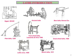
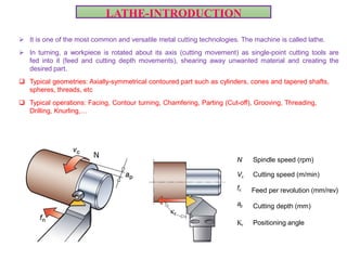
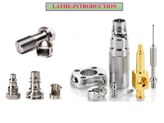
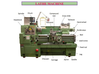
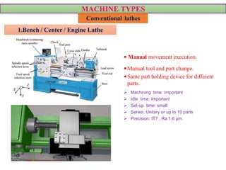
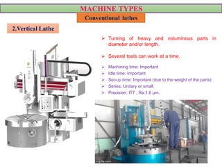
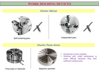
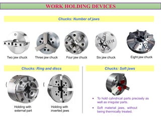
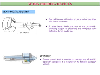
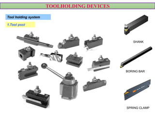
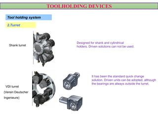
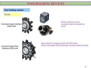
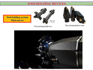
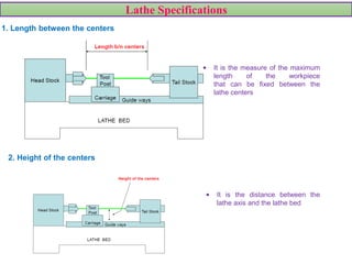
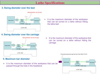
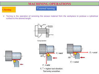
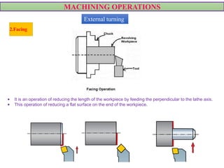
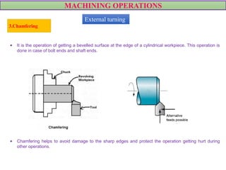
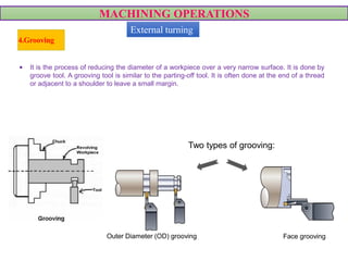
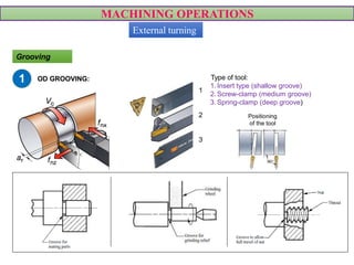
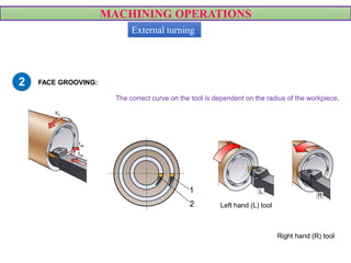
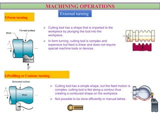
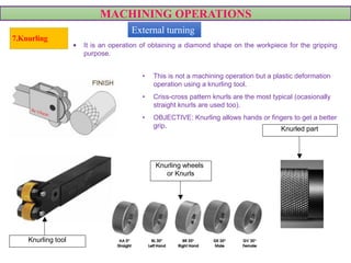
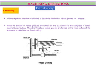
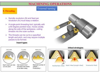
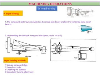
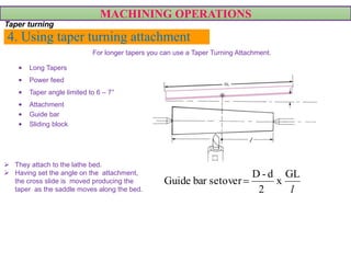
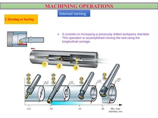
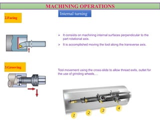
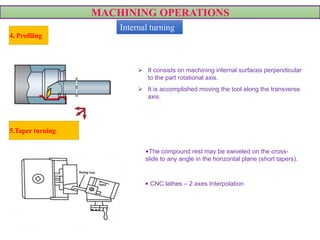
SlideShare a Scribd company logo
LATHE
Bench lathe, 1911
Ancient India Bow lathe, Roman Era
Pole lathe, 1250
Foot wheel lathe,
Leonardo da Vinci 1480
Egypt, 300 BC
Great wheel lathe, 1680
Lathe circa, 1850
2
LATHE-INTRODUCTION
 It is one of the most common and versatile metal cutting technologies. The machine is called lathe.
 In turning, a workpiece is rotated about its axis (cutting movement) as single-point cutting tools are
fed into it (feed and cutting depth movements), shearing away unwanted material and creating the
desired part.
 Typical geometries: Axially-symmetrical contoured part such as cylinders, cones and tapered shafts,
spheres, threads, etc
 Typical operations: Facing, Contour turning, Chamfering, Parting (Cut-off), Grooving, Threading,
Drilling, Knurling,…
LATHE-INTRODUCTION
N
N Spindle speed (rpm)
Vc Cutting speed (m/min)
fn
ap
Feed per revolution (mm/rev)
Cutting depth (mm)
r Positioning angle
VIDEO
LATHE-INTRODUCTION
LATHE MACHINE
MACHINE TYPES
Conventional lathes
MACHINE TYPES
Conventional lathes
• Manual movement execution.
•Manual tool and part change.
•Same part holding device for different
parts.
 Machining time: Important
 Idle time: Important
 Set-up time: small
 Series: Unitary or up to 10 parts
 Precision: IT7 , Ra:1.6 µm.
1.Bench / Center / Engine Lathe
MACHINE TYPES
Conventional lathes
 Turning of heavy and voluminous parts in
diameter and/or length.
 Several tools can work at a time.
 Machining time: Important
 Idle time: Important
 Set-up time: Important (due to the weight of the parts)
 Series: Unitary or small
 Precision: IT7 , Ra:1.6 µm.
2.Vertical Lathe
MACHINE TYPES
Conventional lathes
• SEMIAUTOMATIC lathe.
• Automatic tool change.
• Several tools can work at a time.
• Typical workholding device: collets
• Machining time: Less than in a bench lathe.
• Idle time: Less than in a bench lathe.
• Set-up time: Important at the beginning (all the
tools need to be adjusted).
• Series: 25 parts or more.
• Precision: IT 8 , Ra:1.6 µm.
3.Turret lathe
 The distinguishing feature of this type of lathe is
that the tailstock of an engine lathe is replaced by a
hexagonal turret, on the face of which multiple tools
may be fitted and fed into the work in proper
sequence.
 Due to this arrangement, several different types
of operations can be done on a job without
re-setting of work or tools, and a number of
identical parts can be produced in the
minimum time.
hexagonal turret
MACHINE TYPES
Conventional lathes
3. Capstan and Turret lathes
 Capstan lathes generally deal with short or long rod type blanks held in collet, whereas
turret lathes mostly work on chucking type jobs held in the quick acting chucks
 In capstan lathe, the turret travels with limited stroke length within a saddle type guide
block, called auxiliary bed, which is clamped on the main bed as indicated in Fig. 2,
whereas in turret lathe, the heavy turret being mounted on the saddle which directly slides
with larger stroke length on the main bed as indicated in Fig. 2.
Fig.1 turret lathe. Fig.2 capstan lathe
MACHINE TYPES
Conventional lathes
• Automatic movements execution
using cams.
• Several tools can work at a time.
• Automatic part feed and change.
• Important toolholder cost
• Machining time: Less than in a bench lathe.
• Idle time: Almost zero.
• Set-up time: Important (long tools set-up)
• Series: 1000 parts or more
• Precision: IT 8 , Ra:1.6 µm.
4.Single Spindle Automatic Lathe
VIDEO
MACHINE TYPES
Conventional lathes
• Automatic movements execution.
• Several tools can work at a time.
• Automatic part feed and change.
• Important toolholder cost.
• Highly skilled workforce needed to set the
machine.
• 6 to 8 parts can be produced at a time.
• Machining time: Very low
• Idle time: Almost zero.
• Set-up time: Very Important (long tools set-up)
• Series: 10.000 parts or more
• Precision: IT 7/8 , Ra:1.6 µm.
5.Multi Spindle Automatic Lathe
MACHINE TYPES
Numerical Control Lathes (CNC)
MACHINE TYPES
Numerical Control Lathes (CNC)
• It is the evolution of an engine lathe being equipped with
a CNC control.
• They offer high stability, but slow tool indexing and
changing.
VIDEO
1.Flat bed lathe
Video: Flat bed lathe
MACHINE TYPES
Numerical Control Lathes (CNC)
2.Vertical lathe • It is used for large diameter heavy parts.
• A gantry design with a ram is the base of construction.
• Double ram offers a higher productivity.
• Long tool change time and component loading/unloading.
• Applications: railway wheels, gas/steam/wind turbines,
aero engines,…
VIDEO VIDEO
Video: Vertical lathe
MACHINE TYPES
Numerical Control Lathes (CNC)
• Used when machining from both sides is required
(both spindles synchronize for part changing).
• Higher productivity It may halve the cycle time
compared to a single revolver machine:
• Tandem turning (same side turning).
• Machining operations on the sub-spindle at the same
time as the main spindle.
• Typically 3 turrets (2 for the main spindle and 1 for
the sub-spindle), but 2 turrets also exist.
• Typical applications: Long slender components like
shafts and components machined on both sides.
3.Turning centre
TWIN / DOUBLE / SUB SPINDLE
VIDEO VIDEO
MACHINE TYPES
Numerical Control Lathes (CNC)
• Spindle has the axial movement for workpiece load and
machining, not the tools.
• Nearly always fitted with a bar-feeder ( 0.5mm - 40
mm).
• Uses a headstock possible to machine long components
and small diameters without using a secondary spindle.
• Workpiece clamping system collet.
• Application: complex, precise and small size parts.
VIDEO VIDEO
4. Sliding head machine or Swiss type
lathe (I)
Video: Sliding head machine or Swiss type lathe
MACHINE TYPES
Numerical Control Lathes (CNC)
Sliding head machine or Swiss type lathe
VIDEO
MACHINE TYPES
Numerical Control Lathes (CNC)
• Several technologies are integrated into one
machine: turning, milling, drilling,…
• It has evolved from turning machines.
• The heart of the machine is the tool spindle (B
spindle), which even can be tilted. It provides
milling, drilling and tapping capability along with
turning, facing, grooving and threading.
• This spindle is serviced by an automatic tool
changer that resides outside the cutting zone.
• It may have a double spindle and one/two tool
turrets.
• Application: very complex parts.
5.MULTITASKING MACHINE – HORIZONTAL
MACHINE TYPES
Numerical Control Lathes (CNC)
MULTITASKING MACHINE – HORIZONTAL
Video: multitasking machine – horizontal
MACHINE TYPES
Numerical Control Lathes (CNC)
6.Single Spindle Automatic Lathe
VIDEO
24
MACHINE TYPES
Numerical Control Lathes (CNC)
7.Multiple Spindle Automatic Lathe
VIDEOVIDEO
Video: Multiple Spindle Automatic Lathe
WORK HOLDING DEVICES
1.Jaw chuck
Part clamped within a chuck and with no additional
support (maximum recommended cantilever 1.5 Diameter)
Posibility to hold cylindrical or poligonal parts
(side number equal or multiple to the number of
jaws).
Most common Chuck: Self-centering jaws
Movement controlled by a single screw operated by a “T”
shape key. The jaws move simultaneously and exactly
the same amount of movement toward center.
Cantilever L < 1.5Ø
WORK HOLDING DEVICES
Chucks: Manual
VIDEO
Chucks: Power driven
Pneumatic or Hydraulic Magnetic operated
Centering is more complex.
Working with small workpieces is
more difficult because they lack
sufficient surface area.
Independent jawsSelf-centering jaws
VIDEO
VIDEO
WORK HOLDING DEVICES
Chucks: Number of jaws
Six jaw chuckFour jaw chuckThree jaw chuckTwo jaw chuck Eight jaw chuck
Chucks: Ring and discs
Holding with
external part
Holding with
inverted jaws
Chucks: Soft jaws
• To hold cylindrical parts precisely as
well as irregular parts.
• Soft material jaws, without
being thermically treated. VIDEO
Video: Self-centering jaws Video: Independent jaws
WORK HOLDING DEVICES
2.Jaw Chuck and Center
• Part held on one side within a chuck and on the other
side with a live center.
• A lathe center holds the end of the workpiece,
providing support to preventing the workpiece from
deflecting during machining.
Live Center:
• Center contact point is mounted on bearings and allowed to
spin with workpiece. It is mounted in the tailstock quill (60º
vertex).
VIDEO
WORK HOLDING DEVICES
Between Centers
• Part hold within two centers (live center
and dead center).
• Rotation is produced thanks to a dog. It is
not an energetic holding but it offers an
excellent centering (finishing operations).
Dead Center:
• Solid steel tip that workpiece spins
against. It is mounted in the spindle hole
(60º vertex).
WORK HOLDING DEVICES
3.Face Plates
• It is used to grasp parts with irregular shapes.
• It is used when no other clamping system is valid.
• It is a custom-designed clamp for a particular geometry.
WORK HOLDING DEVICES
4.Steady and Follow rests
Steady rest
• Used in external or internal machining
operations.
• It stands stationary from a rigid mounti
• on the bed, and it supports the workpiece at
the rest's center, typically with three contact
points 120° apart.
ng
Follow rest
• External machining of parts mounted within a
chuck and center.
• It is similar to the steady rest, but it is mounted to
the carriage rather than the bed, which means
that as the tool bit moves, the follower rest
follows along.
VIDEO
VIDEOVIDEO
Video: Follow rest
Video: Steady rest
WORK HOLDING DEVICES
5.Mandrel
• For external/internal concentric machining operations.
• Mandrel: It is a hardened and ground cylindrical piece having undercut centerholes on both ends.
It is used for holding hollow workpieces, or those that have been drilled or bored previously.
Solid mandrel
• Mandrels have a slight taper (1:2000). The workpiece is
just fixed by friction. The ends of the mandrel have
machined flats for the lathe dog to grip.
• Since solid machine mandrels have a very slight taper, they
are limited to workpieces with specific inside diameters.
• The workpiece is mounted on a cylindrical shaft and is
axially fixed using nuts.
• The coaxiality between the inner and outer diameter of the
workpiece depends on the workpiece and mandrel
adjustment.
Gang mandrel
WORK HOLDING DEVICES
Cone mandrel
• The workpice is fixed by means of an elastic collet
(B). The collet is expanded by pressing the nut (D)
against the taper shaft (M).
• On the same mandrel different size elastic collets can
be mounted to fix different diameter workpieces.
Expansion mandrel
• It is a very effective device for holding a part that has a
hole drilled through it.
• The part is secured between the tapers of the mandrel.
VIDEO
WORK HOLDING DEVICES
6.Elastic collets
• Commonly used in turret lathes and automatic
lathes.
• Collet: Taper body with an axial hole where the
workpiece to be machined is introduced (cylindrical,
rectangular, hexagonal,… bars).
• Longitudinal cuts offer elasticity to the collet and a
uniform fixture is obtained.
The taper body is pulled manually or automatically against
the machine frame and the workpiece is fixed by pressure
(axial movement is needed to clamp/unclamp the
workpiece).
VIDEO
TOOLHOLDING DEVICES
TOOLHOLDING DEVICES
Tool holding system
1.Tool post
BORING BAR
SHANK
SPRING CLAMP
TOOLHOLDING DEVICES
Shank turret
VDI turret
(Verein Deutscher
Ingenieure)
Designed for shank and cylindrical
holders. Driven solutions can not be used.
It has been the standard quick change
solution. Driven units can be adopted, although
the bearings are always outside the turret.
Tool holding system
2.Turret
TOOLHOLDING DEVICES
Coromant Capto Interface
(CBI) turret
VIDEO
Coromant Capto Disc
Interface (CDI) turret
Driven solutions can be
mounted inside or outside the
turret.
New solution to replace shank and VDI turrets
Driven tool holder (DTH) bearings mounted inside the turret.
Tool holding system
Turret
44
TOOLHOLDING DEVICES
Four turning tools in one Two turning tools in one
Tool holding system
Mini-turret
Lathe Specifications
1. Length between the centers
• It is the measure of the maximum
length of the workpiece
that can be fixed between the
lathe centers
2. Height of the centers
• It is the distance between the
lathe axis and the lathe bed
Lathe Specifications
3. Swing diameter over the bed
• It is the maximum diameter of the workpiece
that can be turned on a lathe without hitting
the lathe bed
4. Swing diameter over the carriage
• It is the maximum diameter of the workpiece that
can be turned on a lathe without hitting the
carriage
5. Maximum bar diameter
• It is the maximum diameter of the workpiece that can be
passed through the hole in the headstock
MACHINING OPERATIONS
1.Turning
Fr  = higher tool vibration.
Tool entry smoother.
Fr = radial
Fr =radial
Ff = axial
95°
Ff =axial
45°
• Turning is the operation of removing the excess material from the workpiece to produce a cylindrical
surface to the desired length.
External turning
MACHINING OPERATIONS
2.Facing
VIDEO
VIDEO
• It is an operation of reducing the length of the workpiece by feeding the perpendicular to the lathe axis.
• This operation of reducing a flat surface on the end of the workpiece.
External turning
MACHINING OPERATIONS
3.Chamfering
VIDEO
• It is the operation of getting a bevelled surface at the edge of a cylindrical workpiece. This operation is
done in case of bolt ends and shaft ends.
• Chamfering helps to avoid damage to the sharp edges and protect the operation getting hurt during
other operations.
External turning
MACHINING OPERATIONS
4.Grooving
Outer Diameter (OD) grooving Face grooving
VIDEO
• It is the process of reducing the diameter of a workpiece over a very narrow surface. It is done by
groove tool. A grooving tool is similar to the parting-off tool. It is often done at the end of a thread
or adjacent to a shoulder to leave a small margin.
Two types of grooving:
External turning
MACHINING OPERATIONS
Positioning
of the tool
Type of tool:
1.Insert type (shallow groove)
2.Screw-clamp (medium groove)
3.Spring-clamp (deep groove)
1
2
3
OD GROOVING:
VIDEO
1
Grooving
External turning
MACHINING OPERATIONS
The correct curve on the tool is dependent on the radius of the workpiece.
FACE GROOVING:2
VIDEO
Left hand (L) tool
Right hand (R) tool
External turning
MACHINING OPERATIONS
 Cutting tool has a shape that is imparted to the
workpiece by plunging the tool into the
workpiece.
 In form turning, cutting tool is complex and
expensive but feed is linear and does not require
special machine tools or devices.
 Cutting tool has a simple shape, but the feed motion is
complex; cutting tool is fed along a contour thus
creating a contoured shape on the workpiece.
 Not possible to be done efficiently in manual lathes.
5.Form turning
6.Profiling or Contour turning
VIDEO VIDEO
External turning
MACHINING OPERATIONS
• This is not a machining operation but a plastic deformation
operation using a knurling tool.
• Criss-cross pattern knurls are the most typical (ocasionally
straight knurls are used too).
• OBJECTIVE: Knurling allows hands or fingers to get a better
grip.
VIDEO
7.Knurling
Knurling tool
Knurling wheels
or Knurls
Knurled part
• It is an operation of obtaining a diamond shape on the workpiece for the gripping
purpose.
External turning
MACHINING OPERATIONS
8. Threading
• It is the important operation in the lathe to obtain the continuous ”helical grooves” or ” threads’‘.
• When the threads or helical grooves are formed on the out surface of the workpiece is called
external thread cutting. When the threads or helical grooves are formed on the inner surface of the
workpiece is called internal thread cutting.
External turning
MACHINING OPERATIONS
 Spindle revolution (N) and feed per
revolution (fn) must keep a relation.
 A single-point threading tool, typically with
a 60 degree pointed nose, moves axially
along the side of the workpiece, cutting
threads into the outer surface.
 The threads can be cut to a specified
length and pitch, and may require multiple
passes to be formed.
Insert types
Infeed strategies
8. Threading
Each insert can only
cut one pitch.
Can result in burr
formation that needs
to be taken away.
Reduced number of
infeeds
Productivity ↑
VIDEOVIDEOVIDEO
VIDEOVIDEO
External turning
MACHINING OPERATIONS
1. Using a compound slide
2. Using form tools
3. Offsetting the tailstock
4. Using taper turning attachment
1. The compound rest may be swiveled on the cross-slide to any angle in the horizontal plane (short
tapers).
VIDEO
2. By offsetting the tailstock (Long and slim tapers, up to 10-15%).
9. Taper turning
External turning
Taper Turning Methods
1. Using a compound slide
• Limited movement of the compound slide.
• Feeding is by hand and is non-uniform.
• This is responsible for low productivity
and poor surface finish.
• Short and steep tapers can be easily
done.
MACHINING OPERATIONS
Taper turning
D d
ℓ
θ
tan
2
D d
l


 ,
2 c
D d
Noof cuts n
d

 /
L
Time cut
f N

2. Using form tools
• Useful for short tapers, where the steepness is
of no consequence such as for chamfering.
• When turning long tapers with form tools, the
tool would likely to chatter (vibrate) resulting in
poor surface finish.
• However care of the form tools is a careful
exercise.
MACHINING OPERATIONS
Taper turning
Video: form tools
3. Offsetting the tailstock
tan
2
D d
l



 
 
tan certain part length only tobe tapered
,
tan entirepart length tobe tapered
2
2 2
L
offset s
l
D d
L
l
D d D d
l
l



 



 
   

MACHINING OPERATIONS
Taper turning
For tapers on longer shafts, you can offset the tailstock from the centre line.
The limitations are on the size of taper, it will only be
a shallow taper.
Calculations on the offset will be needed.
Video: Offsetting the tailstock
4. Using taper turning attachment
MACHINING OPERATIONS
Taper turning
For longer tapers you can use a Taper Turning Attachment.
Video: taper turning attachment
4. Using taper turning attachment
• Long Tapers
• Power feed
• Taper angle limited to 6 – 7°
• Attachment
• Guide bar
• Sliding block
MACHINING OPERATIONS
Taper turning
l
GL
x
2
d-D
setoverbarGuide 
For longer tapers you can use a Taper Turning Attachment.
 They attach to the lathe bed.
 Having set the angle on the attachment,
the cross slide is moved producing the
taper as the saddle moves along the bed.
MACHINING OPERATIONS
 It consists on increasing a previously drilled workpiece diameter.
This operation is accomplished moving the tool using the
longitudinal carriage.
VIDEO VIDEO
1.Turning or boring
Internal turning
MACHINING OPERATIONS
 It consists on machining internal surfaces perpendicular to the
part rotational axis.
 It is accomplished moving the tool along the transverse axis.
Tool movement using the cross-slide to allow thread exits, outlet for
the use of grinding wheels,…
2.Facing
3.Grooving
Internal turning
MACHINING OPERATIONS
 It consists on machining internal surfaces perpendicular
to the part rotational axis.
 It is accomplished moving the tool along the transverse
axis.
4. Profiling
5.Taper turning
•The compound rest may be swiveled on the cross-
slide to any angle in the horizontal plane (short tapers).
• CNC lathes – 2 axes Interpolation
VIDEO
Internal turning
MACHINING OPERATIONS
It consists on creating a blind hole or a through hole using a
drill. Two ways to obatain a gole:
1. The part spins and the drill has no rotation, only an axial
displacement thanks to the tailstock.
2. Using a live tool.
VIDEO
6. Drilling
WC HSS
Solid carbide drills Indexable insert drills Exchangeable tip drills
TIR(TotalIndicatorRunout)
0,02 mm 0,03 mm 0,02 mm
VIDEO
Internal turning
MACHINING OPERATIONS
 It is a special drilling and
countersank (60º) operation done
with a center drill to fit later a live or
dead center.
7. Center hole machining
 The reaming is a finishing operation to achieve good
dimensional (H6,H7,H8) and surface tolerances depending
on the ream.
 Two ways to ream within the lathe:
 Keeping the part stationary and spinning the ream handle
manually (the handle is supported in the tailstock).
 Spinning the part (Mc) and moving the ream axially (Ma)
(held within a drill chuck).
VIDEO
8.Reaming
Internal turning
MACHINING OPERATIONS
9.Threading
RIGHT SIDE LEFT SIDE
VIDEO
1
SINGLE POINT THREADING TOOL
Internal turning
LATHE MACHINE APPLICATIONS
AEROSPACE APPLICATIONS
4 – FAN CASTING –
Titanium
7 – COMBUSTION CASING –
Heat Resistant Super Alloy
6 – TURBINE DISC –
Heat Resistant Super Alloy
LATHE MACHINE APPLICATIONS
AUTOMOTIVE APPLICATIONS
GEAR WHEEL– Hardened Steel
SHAFT – Cast iron or steel
LATHE MACHINE APPLICATIONS
BIOMEDICALAPPLICATIONS
TULIP HEAD – Titanium
VIDEO
BONE SCREW –
Titanium or Stainless Steel
DENTAL SCREW –
TitaniumVIDEO
LATHE MACHINE APPLICATIONS
OIL & GAS APPLICATIONS
SPOOL BODY –
Steel or inconel
TUBING HANGER –
Steel or inconel
MANDREL – Steel
LATHE MACHINE APPLICATIONS
POWER GENERATION APPLICATIONS
STEAM TURBINE DIAPHRAGM
Stainless steel
LATHE MACHINE APPLICATIONS
POWER GENERATION APPLICATIONS
GAS TURBINE DISC
Inconel or steel
OPERATION OVERVIEW
1.Rough turning: outer diameter, facing
2.Pocketing
3.Grooving
4.Profiling
5.Finishing turning: O.D, I.D, faces
6.Drilling
7.Chamfering (front & back)
LATHE MACHINE APPLICATIONS
WIND POWER APPLICATIONS
GEARBOX SHAFT
Steel
MAIN SHAFT
Steel
OPERATION OVERVIEW
1.Turning – Heavy duty roughing
2.Turning – Semi roughing
3.Turning – Finishing
4.Drilling – Deep hole
5.Drilling – Short hole

More Related Content

What's hot

Lathe Machine
Lathe MachineLathe Machine
Lathe Machine
RANJIT TAWARE
 
11 milling
11 milling11 milling
11 milling
M Siva Kumar
 
Lathe – turning machine
Lathe – turning machineLathe – turning machine
Lathe – turning machine
cpandiv
 
Work holding
Work holdingWork holding
Work holding
MarkLor
 
mesin larik
mesin larikmesin larik
mesin larikfaismoha
 
Lathe machine
Lathe machineLathe machine
Lathe machine
Sagar Joshi
 
Pp lathes
Pp lathesPp lathes
Pp lathes
Maxy2001
 
Automatic lathes
Automatic lathes Automatic lathes
Automatic lathes
POLAYYA CHINTADA
 
Various work holding devices
Various work holding devicesVarious work holding devices
Various work holding devices
Raj Parekh
 
Automatic machines
Automatic machinesAutomatic machines
Automatic machines
rmkcet
 
Lathe presentation
Lathe presentationLathe presentation
Lathe presentation
Reece Hancock
 
Drill jig
Drill jigDrill jig
Drill jig
Amruta Rane
 
Clamping and Clamping Devices
Clamping and Clamping DevicesClamping and Clamping Devices
Clamping and Clamping Devices
Amruta Rane
 
Manufacturing technology II unit - 3
Manufacturing technology II unit - 3Manufacturing technology II unit - 3
Manufacturing technology II unit - 3
Ram Kumar P
 
Lathe-Types, Parts, Feed Mechanisms, Specifications,Lathe Accessories and Att...
Lathe-Types, Parts, Feed Mechanisms, Specifications,Lathe Accessories and Att...Lathe-Types, Parts, Feed Mechanisms, Specifications,Lathe Accessories and Att...
Lathe-Types, Parts, Feed Mechanisms, Specifications,Lathe Accessories and Att...
rajguptanitw
 
Different flanking devices and attachment
Different flanking devices and attachmentDifferent flanking devices and attachment
Different flanking devices and attachmentAlbert Candor
 
The Parts of the lathe machine
The Parts of the lathe machineThe Parts of the lathe machine
The Parts of the lathe machine
duvansaavedra
 

What's hot (20)

Lathe Machine
Lathe MachineLathe Machine
Lathe Machine
 
11 milling
11 milling11 milling
11 milling
 
Lathe – turning machine
Lathe – turning machineLathe – turning machine
Lathe – turning machine
 
Work holding
Work holdingWork holding
Work holding
 
mesin larik
mesin larikmesin larik
mesin larik
 
Lathe machine
Lathe machineLathe machine
Lathe machine
 
Pp lathes
Pp lathesPp lathes
Pp lathes
 
Automatic lathes
Automatic lathes Automatic lathes
Automatic lathes
 
Lathe
LatheLathe
Lathe
 
Capstan, Turret & Automatic lathe
Capstan, Turret & Automatic latheCapstan, Turret & Automatic lathe
Capstan, Turret & Automatic lathe
 
Various work holding devices
Various work holding devicesVarious work holding devices
Various work holding devices
 
Mp 2 report
Mp 2 reportMp 2 report
Mp 2 report
 
Automatic machines
Automatic machinesAutomatic machines
Automatic machines
 
Lathe presentation
Lathe presentationLathe presentation
Lathe presentation
 
Drill jig
Drill jigDrill jig
Drill jig
 
Clamping and Clamping Devices
Clamping and Clamping DevicesClamping and Clamping Devices
Clamping and Clamping Devices
 
Manufacturing technology II unit - 3
Manufacturing technology II unit - 3Manufacturing technology II unit - 3
Manufacturing technology II unit - 3
 
Lathe-Types, Parts, Feed Mechanisms, Specifications,Lathe Accessories and Att...
Lathe-Types, Parts, Feed Mechanisms, Specifications,Lathe Accessories and Att...Lathe-Types, Parts, Feed Mechanisms, Specifications,Lathe Accessories and Att...
Lathe-Types, Parts, Feed Mechanisms, Specifications,Lathe Accessories and Att...
 
Different flanking devices and attachment
Different flanking devices and attachmentDifferent flanking devices and attachment
Different flanking devices and attachment
 
The Parts of the lathe machine
The Parts of the lathe machineThe Parts of the lathe machine
The Parts of the lathe machine
 

Similar to 07 lathe

Lathe Machine
Lathe MachineLathe Machine
Lathe Machine
U.M.Manikanta Demudu
 
lathe machine
lathe machinelathe machine
lathe machine
dataniyaarunkumar
 
Engine lathe ,types of lathes
Engine lathe ,types of lathesEngine lathe ,types of lathes
Engine lathe ,types of lathes
Hema Mahesh
 
341648257-Lathe-Machine.pptx
341648257-Lathe-Machine.pptx341648257-Lathe-Machine.pptx
341648257-Lathe-Machine.pptx
vinoth777429
 
Manufacturing Processes
Manufacturing ProcessesManufacturing Processes
Manufacturing Processes
Ansar Mulla
 
5. Lathe drilling & milling machine.pptx
5. Lathe drilling & milling machine.pptx5. Lathe drilling & milling machine.pptx
5. Lathe drilling & milling machine.pptx
wakurets_21
 
Unit 2 Lathe
Unit 2 LatheUnit 2 Lathe
Unit 2 Lathe
subrabest
 
Presentation1 machine tool and machining
Presentation1 machine tool and machiningPresentation1 machine tool and machining
Presentation1 machine tool and machining
MudassirAliqadri
 
Lathe and other machine tools
Lathe and other machine toolsLathe and other machine tools
Lathe and other machine tools
Dr. Bolleddu Venkateshwarlu
 
LatheMachine_2019-20.pptx
LatheMachine_2019-20.pptxLatheMachine_2019-20.pptx
LatheMachine_2019-20.pptx
balubudida
 
Unit-II Turning Machines.pptx
Unit-II Turning Machines.pptxUnit-II Turning Machines.pptx
Unit-II Turning Machines.pptx
Mohamedsulaiman53
 
Turning
TurningTurning
Turning
endika55
 
Turning Machines
Turning MachinesTurning Machines
Turning Machines
laxtwinsme
 
Basics of lathe machine
Basics of lathe machineBasics of lathe machine
Basics of lathe machine
deept14
 
Introduction to lathe machine
Introduction to lathe machine Introduction to lathe machine
Introduction to lathe machine
Umair Ahmad
 
Lathe parts
Lathe partsLathe parts
Lathe parts
kempaRaju5
 
lathe-151001051314-lva1-app6892 (1).pdf
lathe-151001051314-lva1-app6892 (1).pdflathe-151001051314-lva1-app6892 (1).pdf
lathe-151001051314-lva1-app6892 (1).pdf
PrashantKuwar
 
Turning
TurningTurning
Turning
endika55
 
lathe-151001051314-lva1-app6892_Copy.pdf
lathe-151001051314-lva1-app6892_Copy.pdflathe-151001051314-lva1-app6892_Copy.pdf
lathe-151001051314-lva1-app6892_Copy.pdf
PrashantKuwar
 

Similar to 07 lathe (20)

Lathe Machine
Lathe MachineLathe Machine
Lathe Machine
 
lathe machine
lathe machinelathe machine
lathe machine
 
Engine lathe ,types of lathes
Engine lathe ,types of lathesEngine lathe ,types of lathes
Engine lathe ,types of lathes
 
341648257-Lathe-Machine.pptx
341648257-Lathe-Machine.pptx341648257-Lathe-Machine.pptx
341648257-Lathe-Machine.pptx
 
Manufacturing Processes
Manufacturing ProcessesManufacturing Processes
Manufacturing Processes
 
5. Lathe drilling & milling machine.pptx
5. Lathe drilling & milling machine.pptx5. Lathe drilling & milling machine.pptx
5. Lathe drilling & milling machine.pptx
 
Unit 2 Lathe
Unit 2 LatheUnit 2 Lathe
Unit 2 Lathe
 
Presentation1 machine tool and machining
Presentation1 machine tool and machiningPresentation1 machine tool and machining
Presentation1 machine tool and machining
 
Lathe and other machine tools
Lathe and other machine toolsLathe and other machine tools
Lathe and other machine tools
 
LatheMachine_2019-20.pptx
LatheMachine_2019-20.pptxLatheMachine_2019-20.pptx
LatheMachine_2019-20.pptx
 
Unit-II Turning Machines.pptx
Unit-II Turning Machines.pptxUnit-II Turning Machines.pptx
Unit-II Turning Machines.pptx
 
Turning
TurningTurning
Turning
 
Turning Machines
Turning MachinesTurning Machines
Turning Machines
 
Basics of lathe machine
Basics of lathe machineBasics of lathe machine
Basics of lathe machine
 
Introduction to lathe machine
Introduction to lathe machine Introduction to lathe machine
Introduction to lathe machine
 
Lathe parts
Lathe partsLathe parts
Lathe parts
 
lathe-151001051314-lva1-app6892 (1).pdf
lathe-151001051314-lva1-app6892 (1).pdflathe-151001051314-lva1-app6892 (1).pdf
lathe-151001051314-lva1-app6892 (1).pdf
 
internship report
internship reportinternship report
internship report
 
Turning
TurningTurning
Turning
 
lathe-151001051314-lva1-app6892_Copy.pdf
lathe-151001051314-lva1-app6892_Copy.pdflathe-151001051314-lva1-app6892_Copy.pdf
lathe-151001051314-lva1-app6892_Copy.pdf
 

More from M Siva Kumar

01 introduction to Manufacturing processes
01 introduction to Manufacturing processes01 introduction to Manufacturing processes
01 introduction to Manufacturing processes
M Siva Kumar
 
12 cnc &amp; part programming
12 cnc &amp; part programming12 cnc &amp; part programming
12 cnc &amp; part programming
M Siva Kumar
 
10 gear manufacturing process
10  gear manufacturing process10  gear manufacturing process
10 gear manufacturing process
M Siva Kumar
 
09 abrasive technologies
09 abrasive technologies09 abrasive technologies
09 abrasive technologies
M Siva Kumar
 
08 drilling
08   drilling08   drilling
08 drilling
M Siva Kumar
 
07.1 lathe numerical
07.1 lathe numerical07.1 lathe numerical
07.1 lathe numerical
M Siva Kumar
 
06 tool life
06 tool life06 tool life
06 tool life
M Siva Kumar
 
04 types of chip formation, cutting temperature,etc.,
04 types of chip formation, cutting temperature,etc.,04 types of chip formation, cutting temperature,etc.,
04 types of chip formation, cutting temperature,etc.,
M Siva Kumar
 
03 cutting tool materials
03 cutting tool materials03 cutting tool materials
03 cutting tool materials
M Siva Kumar
 
02 tool terminology
02 tool terminology02 tool terminology
02 tool terminology
M Siva Kumar
 
Plastic forming techniques
Plastic forming techniquesPlastic forming techniques
Plastic forming techniques
M Siva Kumar
 
Rolling Process
Rolling ProcessRolling Process
Rolling Process
M Siva Kumar
 
Extrusion Process
Extrusion ProcessExtrusion Process
Extrusion Process
M Siva Kumar
 
Casting defects
Casting defectsCasting defects
Casting defects
M Siva Kumar
 
Welding defects
Welding defectsWelding defects
Welding defects
M Siva Kumar
 
Gas Welding
Gas WeldingGas Welding
Gas Welding
M Siva Kumar
 
Welding Processes
Welding ProcessesWelding Processes
Welding Processes
M Siva Kumar
 
Special casting Techniques
Special casting TechniquesSpecial casting Techniques
Special casting Techniques
M Siva Kumar
 
Casting
CastingCasting
Casting
M Siva Kumar
 

More from M Siva Kumar (19)

01 introduction to Manufacturing processes
01 introduction to Manufacturing processes01 introduction to Manufacturing processes
01 introduction to Manufacturing processes
 
12 cnc &amp; part programming
12 cnc &amp; part programming12 cnc &amp; part programming
12 cnc &amp; part programming
 
10 gear manufacturing process
10  gear manufacturing process10  gear manufacturing process
10 gear manufacturing process
 
09 abrasive technologies
09 abrasive technologies09 abrasive technologies
09 abrasive technologies
 
08 drilling
08   drilling08   drilling
08 drilling
 
07.1 lathe numerical
07.1 lathe numerical07.1 lathe numerical
07.1 lathe numerical
 
06 tool life
06 tool life06 tool life
06 tool life
 
04 types of chip formation, cutting temperature,etc.,
04 types of chip formation, cutting temperature,etc.,04 types of chip formation, cutting temperature,etc.,
04 types of chip formation, cutting temperature,etc.,
 
03 cutting tool materials
03 cutting tool materials03 cutting tool materials
03 cutting tool materials
 
02 tool terminology
02 tool terminology02 tool terminology
02 tool terminology
 
Plastic forming techniques
Plastic forming techniquesPlastic forming techniques
Plastic forming techniques
 
Rolling Process
Rolling ProcessRolling Process
Rolling Process
 
Extrusion Process
Extrusion ProcessExtrusion Process
Extrusion Process
 
Casting defects
Casting defectsCasting defects
Casting defects
 
Welding defects
Welding defectsWelding defects
Welding defects
 
Gas Welding
Gas WeldingGas Welding
Gas Welding
 
Welding Processes
Welding ProcessesWelding Processes
Welding Processes
 
Special casting Techniques
Special casting TechniquesSpecial casting Techniques
Special casting Techniques
 
Casting
CastingCasting
Casting
 

Recently uploaded

Standard Reomte Control Interface - Neometrix
Standard Reomte Control Interface - NeometrixStandard Reomte Control Interface - Neometrix
Standard Reomte Control Interface - Neometrix
Neometrix_Engineering_Pvt_Ltd
 
Investor-Presentation-Q1FY2024 investor presentation document.pptx
Investor-Presentation-Q1FY2024 investor presentation document.pptxInvestor-Presentation-Q1FY2024 investor presentation document.pptx
Investor-Presentation-Q1FY2024 investor presentation document.pptx
AmarGB2
 
The Benefits and Techniques of Trenchless Pipe Repair.pdf
The Benefits and Techniques of Trenchless Pipe Repair.pdfThe Benefits and Techniques of Trenchless Pipe Repair.pdf
The Benefits and Techniques of Trenchless Pipe Repair.pdf
Pipe Restoration Solutions
 
power quality voltage fluctuation UNIT - I.pptx
power quality voltage fluctuation UNIT - I.pptxpower quality voltage fluctuation UNIT - I.pptx
power quality voltage fluctuation UNIT - I.pptx
ViniHema
 
Planning Of Procurement o different goods and services
Planning Of Procurement o different goods and servicesPlanning Of Procurement o different goods and services
Planning Of Procurement o different goods and services
JoytuBarua2
 
ethical hacking in wireless-hacking1.ppt
ethical hacking in wireless-hacking1.pptethical hacking in wireless-hacking1.ppt
ethical hacking in wireless-hacking1.ppt
Jayaprasanna4
 
Governing Equations for Fundamental Aerodynamics_Anderson2010.pdf
Governing Equations for Fundamental Aerodynamics_Anderson2010.pdfGoverning Equations for Fundamental Aerodynamics_Anderson2010.pdf
Governing Equations for Fundamental Aerodynamics_Anderson2010.pdf
WENKENLI1
 
J.Yang, ICLR 2024, MLILAB, KAIST AI.pdf
J.Yang,  ICLR 2024, MLILAB, KAIST AI.pdfJ.Yang,  ICLR 2024, MLILAB, KAIST AI.pdf
J.Yang, ICLR 2024, MLILAB, KAIST AI.pdf
MLILAB
 
在线办理(ANU毕业证书)澳洲国立大学毕业证录取通知书一模一样
在线办理(ANU毕业证书)澳洲国立大学毕业证录取通知书一模一样在线办理(ANU毕业证书)澳洲国立大学毕业证录取通知书一模一样
在线办理(ANU毕业证书)澳洲国立大学毕业证录取通知书一模一样
obonagu
 
Hierarchical Digital Twin of a Naval Power System
Hierarchical Digital Twin of a Naval Power SystemHierarchical Digital Twin of a Naval Power System
Hierarchical Digital Twin of a Naval Power System
Kerry Sado
 
一比一原版(SFU毕业证)西蒙菲莎大学毕业证成绩单如何办理
一比一原版(SFU毕业证)西蒙菲莎大学毕业证成绩单如何办理一比一原版(SFU毕业证)西蒙菲莎大学毕业证成绩单如何办理
一比一原版(SFU毕业证)西蒙菲莎大学毕业证成绩单如何办理
bakpo1
 
Gen AI Study Jams _ For the GDSC Leads in India.pdf
Gen AI Study Jams _ For the GDSC Leads in India.pdfGen AI Study Jams _ For the GDSC Leads in India.pdf
Gen AI Study Jams _ For the GDSC Leads in India.pdf
gdsczhcet
 
road safety engineering r s e unit 3.pdf
road safety engineering  r s e unit 3.pdfroad safety engineering  r s e unit 3.pdf
road safety engineering r s e unit 3.pdf
VENKATESHvenky89705
 
RAT: Retrieval Augmented Thoughts Elicit Context-Aware Reasoning in Long-Hori...
RAT: Retrieval Augmented Thoughts Elicit Context-Aware Reasoning in Long-Hori...RAT: Retrieval Augmented Thoughts Elicit Context-Aware Reasoning in Long-Hori...
RAT: Retrieval Augmented Thoughts Elicit Context-Aware Reasoning in Long-Hori...
thanhdowork
 
Final project report on grocery store management system..pdf
Final project report on grocery store management system..pdfFinal project report on grocery store management system..pdf
Final project report on grocery store management system..pdf
Kamal Acharya
 
ML for identifying fraud using open blockchain data.pptx
ML for identifying fraud using open blockchain data.pptxML for identifying fraud using open blockchain data.pptx
ML for identifying fraud using open blockchain data.pptx
Vijay Dialani, PhD
 
Immunizing Image Classifiers Against Localized Adversary Attacks
Immunizing Image Classifiers Against Localized Adversary AttacksImmunizing Image Classifiers Against Localized Adversary Attacks
Immunizing Image Classifiers Against Localized Adversary Attacks
gerogepatton
 
Hybrid optimization of pumped hydro system and solar- Engr. Abdul-Azeez.pdf
Hybrid optimization of pumped hydro system and solar- Engr. Abdul-Azeez.pdfHybrid optimization of pumped hydro system and solar- Engr. Abdul-Azeez.pdf
Hybrid optimization of pumped hydro system and solar- Engr. Abdul-Azeez.pdf
fxintegritypublishin
 
Sachpazis:Terzaghi Bearing Capacity Estimation in simple terms with Calculati...
Sachpazis:Terzaghi Bearing Capacity Estimation in simple terms with Calculati...Sachpazis:Terzaghi Bearing Capacity Estimation in simple terms with Calculati...
Sachpazis:Terzaghi Bearing Capacity Estimation in simple terms with Calculati...
Dr.Costas Sachpazis
 
English lab ppt no titlespecENG PPTt.pdf
English lab ppt no titlespecENG PPTt.pdfEnglish lab ppt no titlespecENG PPTt.pdf
English lab ppt no titlespecENG PPTt.pdf
BrazilAccount1
 

Recently uploaded (20)

Standard Reomte Control Interface - Neometrix
Standard Reomte Control Interface - NeometrixStandard Reomte Control Interface - Neometrix
Standard Reomte Control Interface - Neometrix
 
Investor-Presentation-Q1FY2024 investor presentation document.pptx
Investor-Presentation-Q1FY2024 investor presentation document.pptxInvestor-Presentation-Q1FY2024 investor presentation document.pptx
Investor-Presentation-Q1FY2024 investor presentation document.pptx
 
The Benefits and Techniques of Trenchless Pipe Repair.pdf
The Benefits and Techniques of Trenchless Pipe Repair.pdfThe Benefits and Techniques of Trenchless Pipe Repair.pdf
The Benefits and Techniques of Trenchless Pipe Repair.pdf
 
power quality voltage fluctuation UNIT - I.pptx
power quality voltage fluctuation UNIT - I.pptxpower quality voltage fluctuation UNIT - I.pptx
power quality voltage fluctuation UNIT - I.pptx
 
Planning Of Procurement o different goods and services
Planning Of Procurement o different goods and servicesPlanning Of Procurement o different goods and services
Planning Of Procurement o different goods and services
 
ethical hacking in wireless-hacking1.ppt
ethical hacking in wireless-hacking1.pptethical hacking in wireless-hacking1.ppt
ethical hacking in wireless-hacking1.ppt
 
Governing Equations for Fundamental Aerodynamics_Anderson2010.pdf
Governing Equations for Fundamental Aerodynamics_Anderson2010.pdfGoverning Equations for Fundamental Aerodynamics_Anderson2010.pdf
Governing Equations for Fundamental Aerodynamics_Anderson2010.pdf
 
J.Yang, ICLR 2024, MLILAB, KAIST AI.pdf
J.Yang,  ICLR 2024, MLILAB, KAIST AI.pdfJ.Yang,  ICLR 2024, MLILAB, KAIST AI.pdf
J.Yang, ICLR 2024, MLILAB, KAIST AI.pdf
 
在线办理(ANU毕业证书)澳洲国立大学毕业证录取通知书一模一样
在线办理(ANU毕业证书)澳洲国立大学毕业证录取通知书一模一样在线办理(ANU毕业证书)澳洲国立大学毕业证录取通知书一模一样
在线办理(ANU毕业证书)澳洲国立大学毕业证录取通知书一模一样
 
Hierarchical Digital Twin of a Naval Power System
Hierarchical Digital Twin of a Naval Power SystemHierarchical Digital Twin of a Naval Power System
Hierarchical Digital Twin of a Naval Power System
 
一比一原版(SFU毕业证)西蒙菲莎大学毕业证成绩单如何办理
一比一原版(SFU毕业证)西蒙菲莎大学毕业证成绩单如何办理一比一原版(SFU毕业证)西蒙菲莎大学毕业证成绩单如何办理
一比一原版(SFU毕业证)西蒙菲莎大学毕业证成绩单如何办理
 
Gen AI Study Jams _ For the GDSC Leads in India.pdf
Gen AI Study Jams _ For the GDSC Leads in India.pdfGen AI Study Jams _ For the GDSC Leads in India.pdf
Gen AI Study Jams _ For the GDSC Leads in India.pdf
 
road safety engineering r s e unit 3.pdf
road safety engineering  r s e unit 3.pdfroad safety engineering  r s e unit 3.pdf
road safety engineering r s e unit 3.pdf
 
RAT: Retrieval Augmented Thoughts Elicit Context-Aware Reasoning in Long-Hori...
RAT: Retrieval Augmented Thoughts Elicit Context-Aware Reasoning in Long-Hori...RAT: Retrieval Augmented Thoughts Elicit Context-Aware Reasoning in Long-Hori...
RAT: Retrieval Augmented Thoughts Elicit Context-Aware Reasoning in Long-Hori...
 
Final project report on grocery store management system..pdf
Final project report on grocery store management system..pdfFinal project report on grocery store management system..pdf
Final project report on grocery store management system..pdf
 
ML for identifying fraud using open blockchain data.pptx
ML for identifying fraud using open blockchain data.pptxML for identifying fraud using open blockchain data.pptx
ML for identifying fraud using open blockchain data.pptx
 
Immunizing Image Classifiers Against Localized Adversary Attacks
Immunizing Image Classifiers Against Localized Adversary AttacksImmunizing Image Classifiers Against Localized Adversary Attacks
Immunizing Image Classifiers Against Localized Adversary Attacks
 
Hybrid optimization of pumped hydro system and solar- Engr. Abdul-Azeez.pdf
Hybrid optimization of pumped hydro system and solar- Engr. Abdul-Azeez.pdfHybrid optimization of pumped hydro system and solar- Engr. Abdul-Azeez.pdf
Hybrid optimization of pumped hydro system and solar- Engr. Abdul-Azeez.pdf
 
Sachpazis:Terzaghi Bearing Capacity Estimation in simple terms with Calculati...
Sachpazis:Terzaghi Bearing Capacity Estimation in simple terms with Calculati...Sachpazis:Terzaghi Bearing Capacity Estimation in simple terms with Calculati...
Sachpazis:Terzaghi Bearing Capacity Estimation in simple terms with Calculati...
 
English lab ppt no titlespecENG PPTt.pdf
English lab ppt no titlespecENG PPTt.pdfEnglish lab ppt no titlespecENG PPTt.pdf
English lab ppt no titlespecENG PPTt.pdf
 

07 lathe

  • 2. Bench lathe, 1911 Ancient India Bow lathe, Roman Era Pole lathe, 1250 Foot wheel lathe, Leonardo da Vinci 1480 Egypt, 300 BC Great wheel lathe, 1680 Lathe circa, 1850 2 LATHE-INTRODUCTION
  • 3.  It is one of the most common and versatile metal cutting technologies. The machine is called lathe.  In turning, a workpiece is rotated about its axis (cutting movement) as single-point cutting tools are fed into it (feed and cutting depth movements), shearing away unwanted material and creating the desired part.  Typical geometries: Axially-symmetrical contoured part such as cylinders, cones and tapered shafts, spheres, threads, etc  Typical operations: Facing, Contour turning, Chamfering, Parting (Cut-off), Grooving, Threading, Drilling, Knurling,… LATHE-INTRODUCTION N N Spindle speed (rpm) Vc Cutting speed (m/min) fn ap Feed per revolution (mm/rev) Cutting depth (mm) r Positioning angle VIDEO
  • 7. MACHINE TYPES Conventional lathes • Manual movement execution. •Manual tool and part change. •Same part holding device for different parts.  Machining time: Important  Idle time: Important  Set-up time: small  Series: Unitary or up to 10 parts  Precision: IT7 , Ra:1.6 µm. 1.Bench / Center / Engine Lathe
  • 8. MACHINE TYPES Conventional lathes  Turning of heavy and voluminous parts in diameter and/or length.  Several tools can work at a time.  Machining time: Important  Idle time: Important  Set-up time: Important (due to the weight of the parts)  Series: Unitary or small  Precision: IT7 , Ra:1.6 µm. 2.Vertical Lathe
  • 9. MACHINE TYPES Conventional lathes • SEMIAUTOMATIC lathe. • Automatic tool change. • Several tools can work at a time. • Typical workholding device: collets • Machining time: Less than in a bench lathe. • Idle time: Less than in a bench lathe. • Set-up time: Important at the beginning (all the tools need to be adjusted). • Series: 25 parts or more. • Precision: IT 8 , Ra:1.6 µm. 3.Turret lathe  The distinguishing feature of this type of lathe is that the tailstock of an engine lathe is replaced by a hexagonal turret, on the face of which multiple tools may be fitted and fed into the work in proper sequence.  Due to this arrangement, several different types of operations can be done on a job without re-setting of work or tools, and a number of identical parts can be produced in the minimum time. hexagonal turret
  • 10. MACHINE TYPES Conventional lathes 3. Capstan and Turret lathes  Capstan lathes generally deal with short or long rod type blanks held in collet, whereas turret lathes mostly work on chucking type jobs held in the quick acting chucks  In capstan lathe, the turret travels with limited stroke length within a saddle type guide block, called auxiliary bed, which is clamped on the main bed as indicated in Fig. 2, whereas in turret lathe, the heavy turret being mounted on the saddle which directly slides with larger stroke length on the main bed as indicated in Fig. 2. Fig.1 turret lathe. Fig.2 capstan lathe
  • 11. MACHINE TYPES Conventional lathes • Automatic movements execution using cams. • Several tools can work at a time. • Automatic part feed and change. • Important toolholder cost • Machining time: Less than in a bench lathe. • Idle time: Almost zero. • Set-up time: Important (long tools set-up) • Series: 1000 parts or more • Precision: IT 8 , Ra:1.6 µm. 4.Single Spindle Automatic Lathe VIDEO
  • 12. MACHINE TYPES Conventional lathes • Automatic movements execution. • Several tools can work at a time. • Automatic part feed and change. • Important toolholder cost. • Highly skilled workforce needed to set the machine. • 6 to 8 parts can be produced at a time. • Machining time: Very low • Idle time: Almost zero. • Set-up time: Very Important (long tools set-up) • Series: 10.000 parts or more • Precision: IT 7/8 , Ra:1.6 µm. 5.Multi Spindle Automatic Lathe
  • 14. MACHINE TYPES Numerical Control Lathes (CNC) • It is the evolution of an engine lathe being equipped with a CNC control. • They offer high stability, but slow tool indexing and changing. VIDEO 1.Flat bed lathe Video: Flat bed lathe
  • 15. MACHINE TYPES Numerical Control Lathes (CNC) 2.Vertical lathe • It is used for large diameter heavy parts. • A gantry design with a ram is the base of construction. • Double ram offers a higher productivity. • Long tool change time and component loading/unloading. • Applications: railway wheels, gas/steam/wind turbines, aero engines,… VIDEO VIDEO
  • 17. MACHINE TYPES Numerical Control Lathes (CNC) • Used when machining from both sides is required (both spindles synchronize for part changing). • Higher productivity It may halve the cycle time compared to a single revolver machine: • Tandem turning (same side turning). • Machining operations on the sub-spindle at the same time as the main spindle. • Typically 3 turrets (2 for the main spindle and 1 for the sub-spindle), but 2 turrets also exist. • Typical applications: Long slender components like shafts and components machined on both sides. 3.Turning centre TWIN / DOUBLE / SUB SPINDLE VIDEO VIDEO
  • 18. MACHINE TYPES Numerical Control Lathes (CNC) • Spindle has the axial movement for workpiece load and machining, not the tools. • Nearly always fitted with a bar-feeder ( 0.5mm - 40 mm). • Uses a headstock possible to machine long components and small diameters without using a secondary spindle. • Workpiece clamping system collet. • Application: complex, precise and small size parts. VIDEO VIDEO 4. Sliding head machine or Swiss type lathe (I)
  • 19. Video: Sliding head machine or Swiss type lathe
  • 20. MACHINE TYPES Numerical Control Lathes (CNC) Sliding head machine or Swiss type lathe VIDEO
  • 21. MACHINE TYPES Numerical Control Lathes (CNC) • Several technologies are integrated into one machine: turning, milling, drilling,… • It has evolved from turning machines. • The heart of the machine is the tool spindle (B spindle), which even can be tilted. It provides milling, drilling and tapping capability along with turning, facing, grooving and threading. • This spindle is serviced by an automatic tool changer that resides outside the cutting zone. • It may have a double spindle and one/two tool turrets. • Application: very complex parts. 5.MULTITASKING MACHINE – HORIZONTAL
  • 22. MACHINE TYPES Numerical Control Lathes (CNC) MULTITASKING MACHINE – HORIZONTAL
  • 23. Video: multitasking machine – horizontal
  • 24. MACHINE TYPES Numerical Control Lathes (CNC) 6.Single Spindle Automatic Lathe VIDEO 24
  • 25. MACHINE TYPES Numerical Control Lathes (CNC) 7.Multiple Spindle Automatic Lathe VIDEOVIDEO
  • 26. Video: Multiple Spindle Automatic Lathe
  • 28. WORK HOLDING DEVICES 1.Jaw chuck Part clamped within a chuck and with no additional support (maximum recommended cantilever 1.5 Diameter) Posibility to hold cylindrical or poligonal parts (side number equal or multiple to the number of jaws). Most common Chuck: Self-centering jaws Movement controlled by a single screw operated by a “T” shape key. The jaws move simultaneously and exactly the same amount of movement toward center. Cantilever L < 1.5Ø
  • 29. WORK HOLDING DEVICES Chucks: Manual VIDEO Chucks: Power driven Pneumatic or Hydraulic Magnetic operated Centering is more complex. Working with small workpieces is more difficult because they lack sufficient surface area. Independent jawsSelf-centering jaws VIDEO VIDEO
  • 30. WORK HOLDING DEVICES Chucks: Number of jaws Six jaw chuckFour jaw chuckThree jaw chuckTwo jaw chuck Eight jaw chuck Chucks: Ring and discs Holding with external part Holding with inverted jaws Chucks: Soft jaws • To hold cylindrical parts precisely as well as irregular parts. • Soft material jaws, without being thermically treated. VIDEO
  • 31. Video: Self-centering jaws Video: Independent jaws
  • 32. WORK HOLDING DEVICES 2.Jaw Chuck and Center • Part held on one side within a chuck and on the other side with a live center. • A lathe center holds the end of the workpiece, providing support to preventing the workpiece from deflecting during machining. Live Center: • Center contact point is mounted on bearings and allowed to spin with workpiece. It is mounted in the tailstock quill (60º vertex). VIDEO
  • 33. WORK HOLDING DEVICES Between Centers • Part hold within two centers (live center and dead center). • Rotation is produced thanks to a dog. It is not an energetic holding but it offers an excellent centering (finishing operations). Dead Center: • Solid steel tip that workpiece spins against. It is mounted in the spindle hole (60º vertex).
  • 34. WORK HOLDING DEVICES 3.Face Plates • It is used to grasp parts with irregular shapes. • It is used when no other clamping system is valid. • It is a custom-designed clamp for a particular geometry.
  • 35. WORK HOLDING DEVICES 4.Steady and Follow rests Steady rest • Used in external or internal machining operations. • It stands stationary from a rigid mounti • on the bed, and it supports the workpiece at the rest's center, typically with three contact points 120° apart. ng Follow rest • External machining of parts mounted within a chuck and center. • It is similar to the steady rest, but it is mounted to the carriage rather than the bed, which means that as the tool bit moves, the follower rest follows along. VIDEO VIDEOVIDEO
  • 38. WORK HOLDING DEVICES 5.Mandrel • For external/internal concentric machining operations. • Mandrel: It is a hardened and ground cylindrical piece having undercut centerholes on both ends. It is used for holding hollow workpieces, or those that have been drilled or bored previously. Solid mandrel • Mandrels have a slight taper (1:2000). The workpiece is just fixed by friction. The ends of the mandrel have machined flats for the lathe dog to grip. • Since solid machine mandrels have a very slight taper, they are limited to workpieces with specific inside diameters. • The workpiece is mounted on a cylindrical shaft and is axially fixed using nuts. • The coaxiality between the inner and outer diameter of the workpiece depends on the workpiece and mandrel adjustment. Gang mandrel
  • 39. WORK HOLDING DEVICES Cone mandrel • The workpice is fixed by means of an elastic collet (B). The collet is expanded by pressing the nut (D) against the taper shaft (M). • On the same mandrel different size elastic collets can be mounted to fix different diameter workpieces. Expansion mandrel • It is a very effective device for holding a part that has a hole drilled through it. • The part is secured between the tapers of the mandrel. VIDEO
  • 40. WORK HOLDING DEVICES 6.Elastic collets • Commonly used in turret lathes and automatic lathes. • Collet: Taper body with an axial hole where the workpiece to be machined is introduced (cylindrical, rectangular, hexagonal,… bars). • Longitudinal cuts offer elasticity to the collet and a uniform fixture is obtained. The taper body is pulled manually or automatically against the machine frame and the workpiece is fixed by pressure (axial movement is needed to clamp/unclamp the workpiece). VIDEO
  • 42. TOOLHOLDING DEVICES Tool holding system 1.Tool post BORING BAR SHANK SPRING CLAMP
  • 43. TOOLHOLDING DEVICES Shank turret VDI turret (Verein Deutscher Ingenieure) Designed for shank and cylindrical holders. Driven solutions can not be used. It has been the standard quick change solution. Driven units can be adopted, although the bearings are always outside the turret. Tool holding system 2.Turret
  • 44. TOOLHOLDING DEVICES Coromant Capto Interface (CBI) turret VIDEO Coromant Capto Disc Interface (CDI) turret Driven solutions can be mounted inside or outside the turret. New solution to replace shank and VDI turrets Driven tool holder (DTH) bearings mounted inside the turret. Tool holding system Turret 44
  • 45. TOOLHOLDING DEVICES Four turning tools in one Two turning tools in one Tool holding system Mini-turret
  • 47. Lathe Specifications 1. Length between the centers • It is the measure of the maximum length of the workpiece that can be fixed between the lathe centers 2. Height of the centers • It is the distance between the lathe axis and the lathe bed
  • 48. Lathe Specifications 3. Swing diameter over the bed • It is the maximum diameter of the workpiece that can be turned on a lathe without hitting the lathe bed 4. Swing diameter over the carriage • It is the maximum diameter of the workpiece that can be turned on a lathe without hitting the carriage 5. Maximum bar diameter • It is the maximum diameter of the workpiece that can be passed through the hole in the headstock
  • 50. MACHINING OPERATIONS 1.Turning Fr  = higher tool vibration. Tool entry smoother. Fr = radial Fr =radial Ff = axial 95° Ff =axial 45° • Turning is the operation of removing the excess material from the workpiece to produce a cylindrical surface to the desired length. External turning
  • 51. MACHINING OPERATIONS 2.Facing VIDEO VIDEO • It is an operation of reducing the length of the workpiece by feeding the perpendicular to the lathe axis. • This operation of reducing a flat surface on the end of the workpiece. External turning
  • 52. MACHINING OPERATIONS 3.Chamfering VIDEO • It is the operation of getting a bevelled surface at the edge of a cylindrical workpiece. This operation is done in case of bolt ends and shaft ends. • Chamfering helps to avoid damage to the sharp edges and protect the operation getting hurt during other operations. External turning
  • 53. MACHINING OPERATIONS 4.Grooving Outer Diameter (OD) grooving Face grooving VIDEO • It is the process of reducing the diameter of a workpiece over a very narrow surface. It is done by groove tool. A grooving tool is similar to the parting-off tool. It is often done at the end of a thread or adjacent to a shoulder to leave a small margin. Two types of grooving: External turning
  • 54. MACHINING OPERATIONS Positioning of the tool Type of tool: 1.Insert type (shallow groove) 2.Screw-clamp (medium groove) 3.Spring-clamp (deep groove) 1 2 3 OD GROOVING: VIDEO 1 Grooving External turning
  • 55. MACHINING OPERATIONS The correct curve on the tool is dependent on the radius of the workpiece. FACE GROOVING:2 VIDEO Left hand (L) tool Right hand (R) tool External turning
  • 56. MACHINING OPERATIONS  Cutting tool has a shape that is imparted to the workpiece by plunging the tool into the workpiece.  In form turning, cutting tool is complex and expensive but feed is linear and does not require special machine tools or devices.  Cutting tool has a simple shape, but the feed motion is complex; cutting tool is fed along a contour thus creating a contoured shape on the workpiece.  Not possible to be done efficiently in manual lathes. 5.Form turning 6.Profiling or Contour turning VIDEO VIDEO External turning
  • 57. MACHINING OPERATIONS • This is not a machining operation but a plastic deformation operation using a knurling tool. • Criss-cross pattern knurls are the most typical (ocasionally straight knurls are used too). • OBJECTIVE: Knurling allows hands or fingers to get a better grip. VIDEO 7.Knurling Knurling tool Knurling wheels or Knurls Knurled part • It is an operation of obtaining a diamond shape on the workpiece for the gripping purpose. External turning
  • 58. MACHINING OPERATIONS 8. Threading • It is the important operation in the lathe to obtain the continuous ”helical grooves” or ” threads’‘. • When the threads or helical grooves are formed on the out surface of the workpiece is called external thread cutting. When the threads or helical grooves are formed on the inner surface of the workpiece is called internal thread cutting. External turning
  • 59. MACHINING OPERATIONS  Spindle revolution (N) and feed per revolution (fn) must keep a relation.  A single-point threading tool, typically with a 60 degree pointed nose, moves axially along the side of the workpiece, cutting threads into the outer surface.  The threads can be cut to a specified length and pitch, and may require multiple passes to be formed. Insert types Infeed strategies 8. Threading Each insert can only cut one pitch. Can result in burr formation that needs to be taken away. Reduced number of infeeds Productivity ↑ VIDEOVIDEOVIDEO VIDEOVIDEO External turning
  • 60. MACHINING OPERATIONS 1. Using a compound slide 2. Using form tools 3. Offsetting the tailstock 4. Using taper turning attachment 1. The compound rest may be swiveled on the cross-slide to any angle in the horizontal plane (short tapers). VIDEO 2. By offsetting the tailstock (Long and slim tapers, up to 10-15%). 9. Taper turning External turning Taper Turning Methods
  • 61. 1. Using a compound slide • Limited movement of the compound slide. • Feeding is by hand and is non-uniform. • This is responsible for low productivity and poor surface finish. • Short and steep tapers can be easily done. MACHINING OPERATIONS Taper turning D d ℓ θ tan 2 D d l    , 2 c D d Noof cuts n d   / L Time cut f N 
  • 62. 2. Using form tools • Useful for short tapers, where the steepness is of no consequence such as for chamfering. • When turning long tapers with form tools, the tool would likely to chatter (vibrate) resulting in poor surface finish. • However care of the form tools is a careful exercise. MACHINING OPERATIONS Taper turning Video: form tools
  • 63. 3. Offsetting the tailstock tan 2 D d l        tan certain part length only tobe tapered , tan entirepart length tobe tapered 2 2 2 L offset s l D d L l D d D d l l                MACHINING OPERATIONS Taper turning For tapers on longer shafts, you can offset the tailstock from the centre line. The limitations are on the size of taper, it will only be a shallow taper. Calculations on the offset will be needed. Video: Offsetting the tailstock
  • 64. 4. Using taper turning attachment MACHINING OPERATIONS Taper turning For longer tapers you can use a Taper Turning Attachment. Video: taper turning attachment
  • 65. 4. Using taper turning attachment • Long Tapers • Power feed • Taper angle limited to 6 – 7° • Attachment • Guide bar • Sliding block MACHINING OPERATIONS Taper turning l GL x 2 d-D setoverbarGuide  For longer tapers you can use a Taper Turning Attachment.  They attach to the lathe bed.  Having set the angle on the attachment, the cross slide is moved producing the taper as the saddle moves along the bed.
  • 66. MACHINING OPERATIONS  It consists on increasing a previously drilled workpiece diameter. This operation is accomplished moving the tool using the longitudinal carriage. VIDEO VIDEO 1.Turning or boring Internal turning
  • 67. MACHINING OPERATIONS  It consists on machining internal surfaces perpendicular to the part rotational axis.  It is accomplished moving the tool along the transverse axis. Tool movement using the cross-slide to allow thread exits, outlet for the use of grinding wheels,… 2.Facing 3.Grooving Internal turning
  • 68. MACHINING OPERATIONS  It consists on machining internal surfaces perpendicular to the part rotational axis.  It is accomplished moving the tool along the transverse axis. 4. Profiling 5.Taper turning •The compound rest may be swiveled on the cross- slide to any angle in the horizontal plane (short tapers). • CNC lathes – 2 axes Interpolation VIDEO Internal turning
  • 69. MACHINING OPERATIONS It consists on creating a blind hole or a through hole using a drill. Two ways to obatain a gole: 1. The part spins and the drill has no rotation, only an axial displacement thanks to the tailstock. 2. Using a live tool. VIDEO 6. Drilling WC HSS Solid carbide drills Indexable insert drills Exchangeable tip drills TIR(TotalIndicatorRunout) 0,02 mm 0,03 mm 0,02 mm VIDEO Internal turning
  • 70. MACHINING OPERATIONS  It is a special drilling and countersank (60º) operation done with a center drill to fit later a live or dead center. 7. Center hole machining  The reaming is a finishing operation to achieve good dimensional (H6,H7,H8) and surface tolerances depending on the ream.  Two ways to ream within the lathe:  Keeping the part stationary and spinning the ream handle manually (the handle is supported in the tailstock).  Spinning the part (Mc) and moving the ream axially (Ma) (held within a drill chuck). VIDEO 8.Reaming Internal turning
  • 71. MACHINING OPERATIONS 9.Threading RIGHT SIDE LEFT SIDE VIDEO 1 SINGLE POINT THREADING TOOL Internal turning
  • 73. LATHE MACHINE APPLICATIONS AEROSPACE APPLICATIONS 4 – FAN CASTING – Titanium 7 – COMBUSTION CASING – Heat Resistant Super Alloy 6 – TURBINE DISC – Heat Resistant Super Alloy
  • 74. LATHE MACHINE APPLICATIONS AUTOMOTIVE APPLICATIONS GEAR WHEEL– Hardened Steel SHAFT – Cast iron or steel
  • 75. LATHE MACHINE APPLICATIONS BIOMEDICALAPPLICATIONS TULIP HEAD – Titanium VIDEO BONE SCREW – Titanium or Stainless Steel DENTAL SCREW – TitaniumVIDEO
  • 76. LATHE MACHINE APPLICATIONS OIL & GAS APPLICATIONS SPOOL BODY – Steel or inconel TUBING HANGER – Steel or inconel MANDREL – Steel
  • 77. LATHE MACHINE APPLICATIONS POWER GENERATION APPLICATIONS STEAM TURBINE DIAPHRAGM Stainless steel
  • 78. LATHE MACHINE APPLICATIONS POWER GENERATION APPLICATIONS GAS TURBINE DISC Inconel or steel OPERATION OVERVIEW 1.Rough turning: outer diameter, facing 2.Pocketing 3.Grooving 4.Profiling 5.Finishing turning: O.D, I.D, faces 6.Drilling 7.Chamfering (front & back)
  • 79. LATHE MACHINE APPLICATIONS WIND POWER APPLICATIONS GEARBOX SHAFT Steel MAIN SHAFT Steel OPERATION OVERVIEW 1.Turning – Heavy duty roughing 2.Turning – Semi roughing 3.Turning – Finishing 4.Drilling – Deep hole 5.Drilling – Short hole