Download as PDF, PPTX

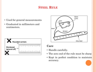


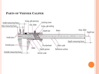


This document provides information on various measuring instruments used in manufacturing, including their construction, operation, and proper use. It discusses steel rules, calipers, micrometers, height gauges, and gauge blocks. For Vernier calipers and micrometers, it explains how to take accurate measurements using the main and Vernier scales, and provides examples of calculating total readings. The document emphasizes proper techniques and care for these precision measuring tools.