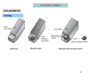
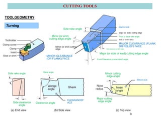
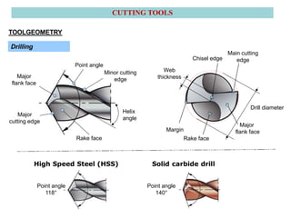
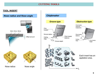
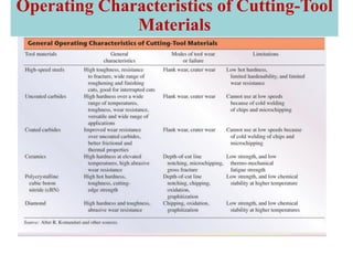
1. The document discusses different types of cutting tool materials, including their properties and applications. It covers solid tools, brazed inserts, mechanically clamped inserts, and various geometries for turning tools.
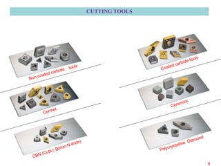
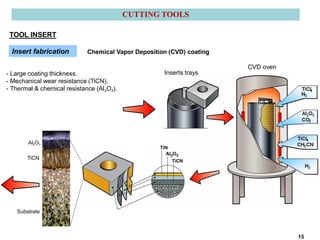
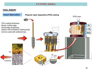
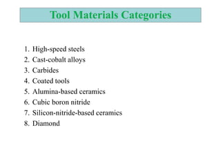
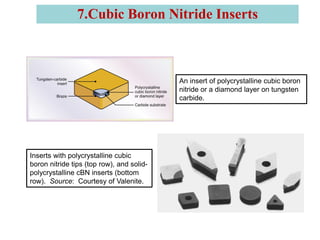
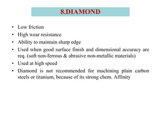
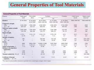
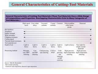
2. Key tool materials discussed are high-speed steels, cast cobalt alloys, tungsten carbide, ceramic tools, cubic boron nitride, and diamond. Coated tools using titanium nitride, aluminum oxide and other coatings are also covered.
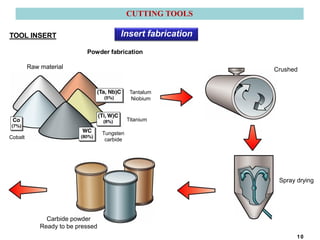
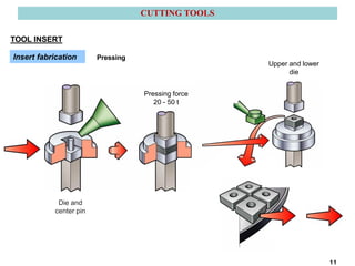
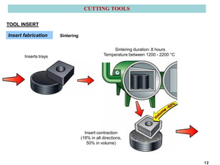
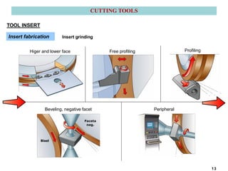
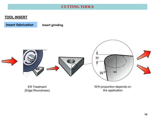
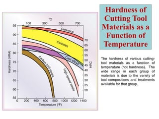
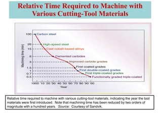
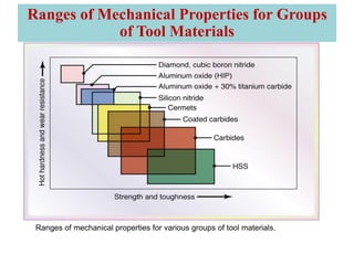
3. Manufacturing processes for inserts including powder metallurgy, sintering, grinding, and chemical or physical vapor deposition coating are summarized. Characteristics such as hardness, toughness, wear resistance and their variation with temperature are compared