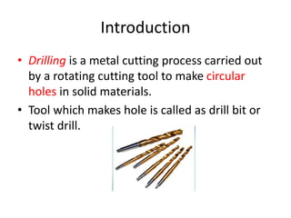
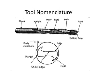
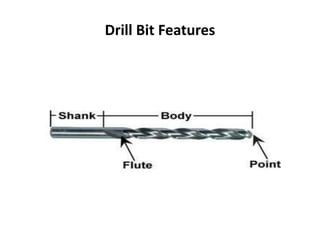
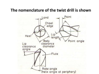
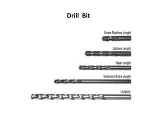
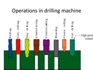
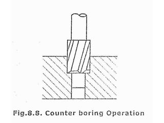
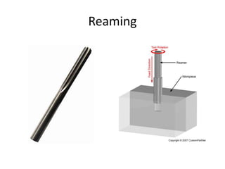
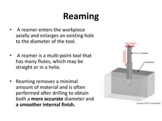
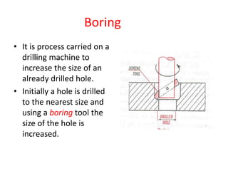
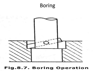
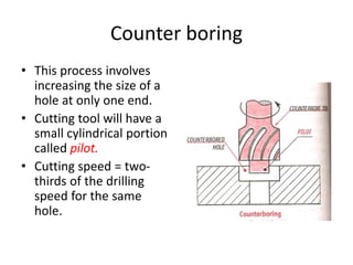
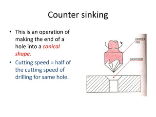
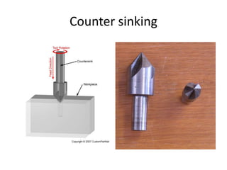
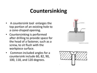
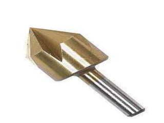
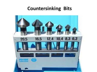
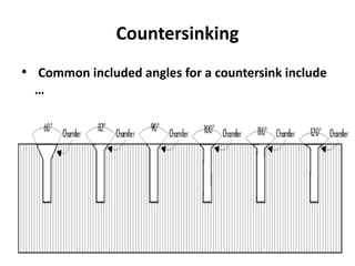
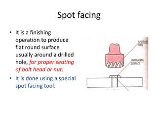
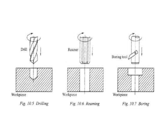
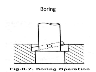
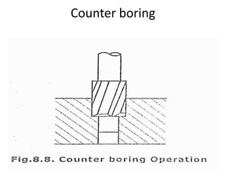
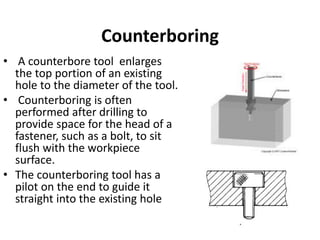
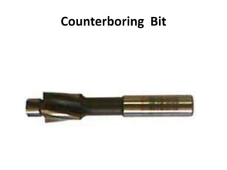
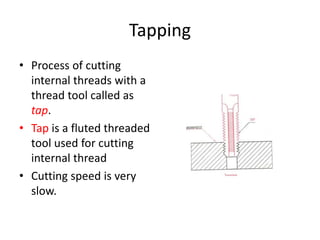
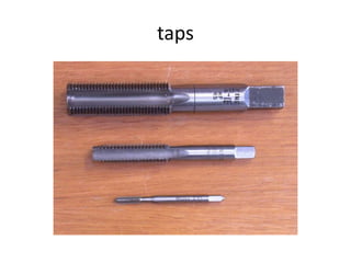
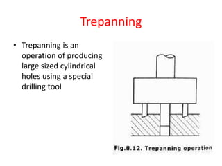
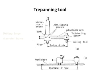
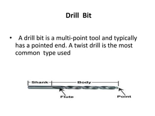
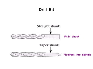
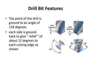
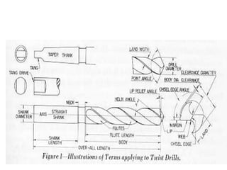
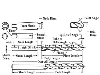
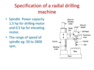
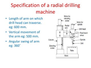
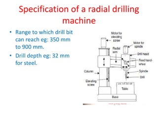
Drilling machine
Introduction
• Drilling is a metal cutting process carried out
by a rotating cutting tool to make circular
holes in solid materials.
• Tool which makes hole is called as drill bit or
twist drill.
Drilling
• Drilling is the operation of producing circular hole in the
work-piece by using a rotating cutter called DRILL.
• The machine used for drilling is called drilling machine.
• The drilling operation can also be accomplished in lathe, in
which the drill is held in tailstock and the work is held by
the chuck.
• The most common drill used is the twist drill.
Tool Nomenclature
Drill Bit
• A drill bit is a multi-point tool and typically
has a pointed end. A twist drill is the most
common type used
Drill Bit
• The twist drill or drill bit is made from High
Speed Steel, tempered to give maximum
hardness throughout the parallel cutting
portion.
• Flutes are incorporated to carry away the
chips of metal and the outside surface is
relieved to produce a cutting edge along the
leading side of each flute.
Twist drill
• Twist drills are available with parallel shanks up to
16mm diameter and with taper shanks up to 100mm
diameter and are made from high-speed steel.
• Standard lengths are known as jobber-series twist
drills, short drills are known as stub series, and long
drills as long series and extra long series.
• Different helix angles are available for drilling a
range of materials
Drill Bit
Fit in chuck
Fit direct into spindle
Drill Bit Features
Drill Bit Features
• The point of the drill is
ground to an angle of
118 degrees
• each side is ground
back to give " relief " of
about 12 degrees to
each cutting edge as
shown
The nomenclature of the twist drill is shown
Twist drills - Helix Types
• The helix angle of the twist drill is the
equivalent of the rake angle on other cutting
tools and is established during manufacture.
• The standard helix angle is 30 degrees, which,
together with a point angle of 118°, is suitable
for drilling steel and cast iron.
Helix types
Standard quick helix
slow
Helix types
• Drills with a helix angle of 20° — known as slow-helix
drills — are available with a point angle of 118° for
cutting brass and bronze and with a point angle of
90° for cutting plastics materials.
• Quick-helix drills, with a helix angle of 40° and a
point angle of 100°, are suitable for drilling the softer
materials such as aluminium alloys and copper
Drill Bit
Wood bits
masonry
steel
Subland drills
• Combination drills known as Subland drills combine a
number of operations in a single tool; for example …
• drill and ream,
• drill two diameters,
• drill and chamfer,
• drill and spotface,
• drill and counterbore,
• Each cutting edge has a separate land and flute, fig.
which enables cutting to take place and resharpening
to be easily carried out.
Subland drill
Examples of Subland-drill applications
Drilling machine
• A power operated machine tool which holds
the drill in its spindle rotating at high speeds
and when actuated move linearly against the
work piece produces a hole.
Types of drilling machine.
• Portable drilling machine
• Bench drilling machine
• Radial drilling machine
• Pillar drilling machine
• Gang drilling machine
• Multiple drilling machine
Portable drilling machine
Bench drilling machine
• These are light duty machines used in small
workshops.
• Also called Sensitive drilling machines because
of its accurate and well balanced spindle.
• Holes of diameter 1 mm to 15 mm.
Bench drilling machine
parts
• Vertical main column
• Base
• Moving drill head
• Work table
• Electric motor
• Variable speed gear box
and spindle feed
mechanism.
working
• Work piece with the exact location marked on
it with the centre punch is clamped rigidly on
the work table.
• spindle axis and center punch indentation are
in same line.
• Machine is started and drill bit is lowered by
rotating feed handle.
• Drill bit touches the work and starts removing
material.
Bench drilling machine
Radial drilling machine
• These are heavy duty and versatile drilling
machine used to perform drilling operate on
large and heavy work piece.
• Holes up to 7.5 cm.
Radial drilling machine
Radial drilling machine-Parts
• Heavy base
• Table
• Vertical column
• Radial arm
• Drill head
• Elevating screw
• Motor for Elevating
screw
• Motor for spindle
Radial drilling machine-Working
• Radial Drilling Machine:- These drilling
machines are used to drill large diameter holes,
multiple holes in one setting of the heavy and
large work pieces.
Radial drilling machine-Working
• This usually large drilling machine possesses a
radial arm which along with the drilling head
can swing and move vertically up and down .
The radial, vertical and swing movement of
the drilling head enables locating the drill
spindle at any point within a very large space
on workpiece and odd shaped jobs. There are
some more versatile radial drilling machines
where the drill spindle can be additionally
swivelled and / or tilted.
Drilling machine operation
• Reaming
• Boring
• Counter boring
• Counter sinking
• Spot facing
• Tapping
Operations in drilling machine
Reaming
• It is a process of smoothing the surface of
drilled holes with a tool.
• Tool is called as reamer.
• Initially a hole is drilled slightly smaller in size.
• Drill is replaced by reamer.
• Speed is reduced to half that of the drilling.
Reaming
Reaming
• A reamer enters the workpiece
axially and enlarges an existing hole
to the diameter of the tool.
• A reamer is a multi-point tool that
has many flutes, which may be
straight or in a helix.
• Reaming removes a minimal
amount of material and is often
performed after drilling to obtain
both a more accurate diameter and
a smoother internal finish.
Boring
• It is process carried on a
drilling machine to
increase the size of an
already drilled hole.
• Initially a hole is drilled
to the nearest size and
using a boring tool the
size of the hole is
increased.
Boring
Counter boring
• This process involves
increasing the size of a
hole at only one end.
• Cutting tool will have a
small cylindrical portion
called pilot.
• Cutting speed = two-
thirds of the drilling
speed for the same
hole.
Counter sinking
• This is an operation of
making the end of a
hole into a conical
shape.
• Cutting speed = half of
the cutting speed of
drilling for same hole.
Counter sinking
Countersinking
• A countersink tool enlarges the
top portion of an existing hole to
a cone-shaped opening.
• Countersinking is performed
after drilling to provide space for
the head of a fastener, such as a
screw, to sit flush with the
workpiece surface.
• Common included angles for a
countersink include 60, 82, 90,
100, 118, and 120 degrees.
Countersinking Bits
Countersinking
• Common included angles for a countersink include
…
Spot facing
• It is a finishing
operation to produce
flat round surface
usually around a drilled
hole, for proper seating
of bolt head or nut.
• It is done using a special
spot facing tool.
Spotfacing
• Spotfacing provides a seat or flat surface at the
entrance and surrounding area of a hole.
• This flat surface allows the bottom of a screw or bolt
to seat squarely with the material.
• Spotfacing is commonly done on castings where
irregular surfaces are found.
• Spotfacing may be performed on a drill press with a
counterbore of suitable size for the operation.
• A proper size pilot must be used whenever this is
done on the drill press.
Spotfacing
spotface
Making a sloped
surface flat
To seat a nut
Back
spotface
Spotting
• Where holes in two parts are required to line
up with each other, a technique known as
‘spotting’ is carried out. The top part is
marked out and drilled.
• The two parts are then carefully positioned
and clamped together.
Boring
Counter boring
Counterboring
• A counterbore tool enlarges
the top portion of an existing
hole to the diameter of the tool.
• Counterboring is often
performed after drilling to
provide space for the head of a
fastener, such as a bolt, to sit
flush with the workpiece
surface.
• The counterboring tool has a
pilot on the end to guide it
straight into the existing hole
Counterboring Bit
Tapping
• Process of cutting
internal threads with a
thread tool called as
tap.
• Tap is a fluted threaded
tool used for cutting
internal thread
• Cutting speed is very
slow.
taps
Trepanning
• Trepanning is an
operation of producing
large sized cylindrical
holes using a special
drilling tool
Trepanning tool
Drilling large
diameter holes
Trepanning Tools
Drilling Machine Vice
• The Machine Vice has
slots in the side of the
base of the vice which
enable the user to
screw the Machine Vice
to the Drilling Machine
table.
Direct Clamping
Clamping set
Drill Bit
• A drill bit is a multi-point tool and typically
has a pointed end. A twist drill is the most
common type used
Drill Bit
• The twist drill or drill bit is made from High
Speed Steel, tempered to give maximum
hardness throughout the parallel cutting
portion.
• Flutes are incorporated to carry away the
chips of metal and the outside surface is
relieved to produce a cutting edge along the
leading side of each flute.
Twist drill
• Twist drills are available with parallel shanks up to
16mm diameter and with taper shanks up to 100mm
diameter and are made from high-speed steel.
• Standard lengths are known as jobber-series twist
drills, short drills are known as stub series, and long
drills as long series and extra long series.
• Different helix angles are available for drilling a
range of materials
Drill Bit
Fit in chuck
Fit direct into spindle
Drill Bit Features
Drill Bit Features
• The point of the drill is
ground to an angle of
118 degrees
• each side is ground
back to give " relief " of
about 12 degrees to
each cutting edge as
shown
The nomenclature of the twist drill is shown
Twist drills - Helix Types
• The helix angle of the twist drill is the
equivalent of the rake angle on other cutting
tools and is established during manufacture.
• The standard helix angle is 30 degrees, which,
together with a point angle of 118°, is suitable
for drilling steel and cast iron.
Helix types
Standard quick helix
slow
Helix types
• Drills with a helix angle of 20° — known as slow-helix
drills — are available with a point angle of 118° for
cutting brass and bronze and with a point angle of
90° for cutting plastics materials.
• Quick-helix drills, with a helix angle of 40° and a
point angle of 100°, are suitable for drilling the softer
materials such as aluminium alloys and copper
Drill Bit
Wood bits
masonry
steel
Subland drills
• Combination drills known as Subland drills combine a
number of operations in a single tool; for example …
• drill and ream,
• drill two diameters,
• drill and chamfer,
• drill and spotface,
• drill and counterbore,
• Each cutting edge has a separate land and flute, fig.
which enables cutting to take place and resharpening
to be easily carried out.
Subland drill
Examples of Subland-drill applications
Tool Holding
Tool Holding parallel shank drill
• Drills and similar tools with
parallel shanks are held in a drill
chuck.
• By rotating the outer sleeve, the
jaws can be opened and closed.
• To ensure maximum grip, the
chuck should be tightened using
the correct size of chuck key. This
prevents the drill from spinning
during use and chewing up the
drill shank.
Drill bit is only gripped by the shank
The Drill Chuck
Chuck
Morse Taper
Chuck Key
Keyless
Chuck
Tool Holding
• The chuck is fitted with a Morse-taper shank which fits into a
corresponding Morse taper in the spindle.
• The size of Morse taper is identified from smallest to largest
by the numbers 1, 2, 3, 4, 5, and 6. The included angle of each
taper is different but is very small, being in the region of 3
degrees.
• If the two mating tapered surfaces are clean and in good
condition, this shallow taper is sufficient to provide a drive
between the two surfaces.
• At the end of the taper shank, two fiats are machined, leaving
a portion known as the tang. This tang fits in a slot on the
inside of the spindle and its main purpose is for the removal
of the shank.
• Drills are also available with Morse-taper shanks which fit
directly into the spindle without the need for a chuck.
Tool Holding
Holding taper shank drills
Tool Holding
• Where a cutting tool or chuck has a Morse taper
smaller than that of the spindle, the difference is
made up by using a sleeve.
• Morse Taper Sleeve
• For example, a drill with a No. 1 Morse-taper shank
to be fitted in a spindle with a No. 2 Morse taper
would require a 1—2 sleeve.
Morse Taper Sleeve
Drill Drift
• To remove a shank from the spindle, a taper key known as a drift is used.
Using the drill drift
• The drift is inserted through a slot in the spindle
Strike here
to remove
Most modern machines
have a built-in drift
Specification of a radial drilling
machine
1.Max.depth hole can be drilled in MM
2.Max drilling radius in mm
3. Min. drilling radius in mm
4.Vertical power movement of arm in MM
5.Horizantal power movement of drill head on
arm in MM
6.Drilling motor power in kw (1.5kw)
7.Spindle speed rang rpm (50-2800rpm)
Specification of a radial drilling
machine
• Spindle Power capacity
1.5 hp for drilling motor
and 0.5 hp for elevating
motor.
• The range of speed of
spindle eg: 50 to 2800
rpm.
Specification of a radial drilling
machine
• Length of arm on which
drill head can traverse.
eg: 600 mm.
• Vertical movement of
the arm eg: 500 mm.
• Angular swing of arm
eg: 360˚
Specification of a radial drilling
machine
• Range to which drill bit
can reach eg: 350 mm
to 900 mm.
• Drill depth eg: 32 mm
for steel.
Precautions for Drilling machine
• Lubrication is important to remove heat and
friction.
• Machines should be cleaned after use
• Chips should be removed using brush.
• T-slots, grooves, spindles sleeves, belts, pulley
should be cleaned.
• Machines should be lightly oiled to prevent
from rusting
Safety Precautions
• Do not support the work piece by hand – use work
holding device.
• Use brush to clean the chip
• No adjustments while the machine is operating
• Ensure for the cutting tools running straight before
starting the operation.
• Never place tools on the drilling table
• Avoid loose clothing and protect the eyes.
• Ease the feed if drill breaks inside the work piece.
drilling-machine.ppt

drilling-machine.ppt

  • 1.
  • 2.
    Introduction • Drilling isa metal cutting process carried out by a rotating cutting tool to make circular holes in solid materials. • Tool which makes hole is called as drill bit or twist drill.
  • 3.
    Drilling • Drilling isthe operation of producing circular hole in the work-piece by using a rotating cutter called DRILL. • The machine used for drilling is called drilling machine. • The drilling operation can also be accomplished in lathe, in which the drill is held in tailstock and the work is held by the chuck. • The most common drill used is the twist drill.
  • 4.
  • 5.
    Drill Bit • Adrill bit is a multi-point tool and typically has a pointed end. A twist drill is the most common type used
  • 6.
    Drill Bit • Thetwist drill or drill bit is made from High Speed Steel, tempered to give maximum hardness throughout the parallel cutting portion. • Flutes are incorporated to carry away the chips of metal and the outside surface is relieved to produce a cutting edge along the leading side of each flute.
  • 7.
    Twist drill • Twistdrills are available with parallel shanks up to 16mm diameter and with taper shanks up to 100mm diameter and are made from high-speed steel. • Standard lengths are known as jobber-series twist drills, short drills are known as stub series, and long drills as long series and extra long series. • Different helix angles are available for drilling a range of materials
  • 8.
    Drill Bit Fit inchuck Fit direct into spindle
  • 9.
  • 10.
    Drill Bit Features •The point of the drill is ground to an angle of 118 degrees • each side is ground back to give " relief " of about 12 degrees to each cutting edge as shown
  • 11.
    The nomenclature ofthe twist drill is shown
  • 12.
    Twist drills -Helix Types • The helix angle of the twist drill is the equivalent of the rake angle on other cutting tools and is established during manufacture. • The standard helix angle is 30 degrees, which, together with a point angle of 118°, is suitable for drilling steel and cast iron.
  • 13.
  • 14.
    Helix types • Drillswith a helix angle of 20° — known as slow-helix drills — are available with a point angle of 118° for cutting brass and bronze and with a point angle of 90° for cutting plastics materials. • Quick-helix drills, with a helix angle of 40° and a point angle of 100°, are suitable for drilling the softer materials such as aluminium alloys and copper
  • 15.
  • 16.
  • 17.
    Subland drills • Combinationdrills known as Subland drills combine a number of operations in a single tool; for example … • drill and ream, • drill two diameters, • drill and chamfer, • drill and spotface, • drill and counterbore, • Each cutting edge has a separate land and flute, fig. which enables cutting to take place and resharpening to be easily carried out.
  • 18.
    Subland drill Examples ofSubland-drill applications
  • 19.
    Drilling machine • Apower operated machine tool which holds the drill in its spindle rotating at high speeds and when actuated move linearly against the work piece produces a hole.
  • 20.
    Types of drillingmachine. • Portable drilling machine • Bench drilling machine • Radial drilling machine • Pillar drilling machine • Gang drilling machine • Multiple drilling machine
  • 21.
  • 22.
    Bench drilling machine •These are light duty machines used in small workshops. • Also called Sensitive drilling machines because of its accurate and well balanced spindle. • Holes of diameter 1 mm to 15 mm.
  • 23.
  • 24.
    parts • Vertical maincolumn • Base • Moving drill head • Work table • Electric motor • Variable speed gear box and spindle feed mechanism.
  • 25.
    working • Work piecewith the exact location marked on it with the centre punch is clamped rigidly on the work table. • spindle axis and center punch indentation are in same line. • Machine is started and drill bit is lowered by rotating feed handle. • Drill bit touches the work and starts removing material.
  • 26.
  • 27.
    Radial drilling machine •These are heavy duty and versatile drilling machine used to perform drilling operate on large and heavy work piece. • Holes up to 7.5 cm.
  • 28.
  • 29.
  • 30.
    Radial drilling machine-Parts •Heavy base • Table • Vertical column • Radial arm • Drill head • Elevating screw • Motor for Elevating screw • Motor for spindle
  • 31.
    Radial drilling machine-Working •Radial Drilling Machine:- These drilling machines are used to drill large diameter holes, multiple holes in one setting of the heavy and large work pieces.
  • 32.
    Radial drilling machine-Working •This usually large drilling machine possesses a radial arm which along with the drilling head can swing and move vertically up and down . The radial, vertical and swing movement of the drilling head enables locating the drill spindle at any point within a very large space on workpiece and odd shaped jobs. There are some more versatile radial drilling machines where the drill spindle can be additionally swivelled and / or tilted.
  • 33.
    Drilling machine operation •Reaming • Boring • Counter boring • Counter sinking • Spot facing • Tapping
  • 34.
  • 35.
    Reaming • It isa process of smoothing the surface of drilled holes with a tool. • Tool is called as reamer. • Initially a hole is drilled slightly smaller in size. • Drill is replaced by reamer. • Speed is reduced to half that of the drilling.
  • 37.
  • 38.
    Reaming • A reamerenters the workpiece axially and enlarges an existing hole to the diameter of the tool. • A reamer is a multi-point tool that has many flutes, which may be straight or in a helix. • Reaming removes a minimal amount of material and is often performed after drilling to obtain both a more accurate diameter and a smoother internal finish.
  • 39.
    Boring • It isprocess carried on a drilling machine to increase the size of an already drilled hole. • Initially a hole is drilled to the nearest size and using a boring tool the size of the hole is increased.
  • 40.
  • 41.
    Counter boring • Thisprocess involves increasing the size of a hole at only one end. • Cutting tool will have a small cylindrical portion called pilot. • Cutting speed = two- thirds of the drilling speed for the same hole.
  • 42.
    Counter sinking • Thisis an operation of making the end of a hole into a conical shape. • Cutting speed = half of the cutting speed of drilling for same hole.
  • 43.
  • 44.
    Countersinking • A countersinktool enlarges the top portion of an existing hole to a cone-shaped opening. • Countersinking is performed after drilling to provide space for the head of a fastener, such as a screw, to sit flush with the workpiece surface. • Common included angles for a countersink include 60, 82, 90, 100, 118, and 120 degrees.
  • 46.
  • 47.
    Countersinking • Common includedangles for a countersink include …
  • 48.
    Spot facing • Itis a finishing operation to produce flat round surface usually around a drilled hole, for proper seating of bolt head or nut. • It is done using a special spot facing tool.
  • 49.
    Spotfacing • Spotfacing providesa seat or flat surface at the entrance and surrounding area of a hole. • This flat surface allows the bottom of a screw or bolt to seat squarely with the material. • Spotfacing is commonly done on castings where irregular surfaces are found. • Spotfacing may be performed on a drill press with a counterbore of suitable size for the operation. • A proper size pilot must be used whenever this is done on the drill press.
  • 50.
    Spotfacing spotface Making a sloped surfaceflat To seat a nut Back spotface
  • 51.
    Spotting • Where holesin two parts are required to line up with each other, a technique known as ‘spotting’ is carried out. The top part is marked out and drilled. • The two parts are then carefully positioned and clamped together.
  • 53.
  • 54.
  • 55.
    Counterboring • A counterboretool enlarges the top portion of an existing hole to the diameter of the tool. • Counterboring is often performed after drilling to provide space for the head of a fastener, such as a bolt, to sit flush with the workpiece surface. • The counterboring tool has a pilot on the end to guide it straight into the existing hole
  • 56.
  • 57.
    Tapping • Process ofcutting internal threads with a thread tool called as tap. • Tap is a fluted threaded tool used for cutting internal thread • Cutting speed is very slow.
  • 58.
  • 59.
    Trepanning • Trepanning isan operation of producing large sized cylindrical holes using a special drilling tool
  • 60.
  • 62.
  • 63.
    Drilling Machine Vice •The Machine Vice has slots in the side of the base of the vice which enable the user to screw the Machine Vice to the Drilling Machine table.
  • 64.
  • 65.
    Drill Bit • Adrill bit is a multi-point tool and typically has a pointed end. A twist drill is the most common type used
  • 66.
    Drill Bit • Thetwist drill or drill bit is made from High Speed Steel, tempered to give maximum hardness throughout the parallel cutting portion. • Flutes are incorporated to carry away the chips of metal and the outside surface is relieved to produce a cutting edge along the leading side of each flute.
  • 67.
    Twist drill • Twistdrills are available with parallel shanks up to 16mm diameter and with taper shanks up to 100mm diameter and are made from high-speed steel. • Standard lengths are known as jobber-series twist drills, short drills are known as stub series, and long drills as long series and extra long series. • Different helix angles are available for drilling a range of materials
  • 68.
    Drill Bit Fit inchuck Fit direct into spindle
  • 69.
  • 70.
    Drill Bit Features •The point of the drill is ground to an angle of 118 degrees • each side is ground back to give " relief " of about 12 degrees to each cutting edge as shown
  • 71.
    The nomenclature ofthe twist drill is shown
  • 75.
    Twist drills -Helix Types • The helix angle of the twist drill is the equivalent of the rake angle on other cutting tools and is established during manufacture. • The standard helix angle is 30 degrees, which, together with a point angle of 118°, is suitable for drilling steel and cast iron.
  • 76.
  • 77.
    Helix types • Drillswith a helix angle of 20° — known as slow-helix drills — are available with a point angle of 118° for cutting brass and bronze and with a point angle of 90° for cutting plastics materials. • Quick-helix drills, with a helix angle of 40° and a point angle of 100°, are suitable for drilling the softer materials such as aluminium alloys and copper
  • 78.
  • 79.
  • 80.
    Subland drills • Combinationdrills known as Subland drills combine a number of operations in a single tool; for example … • drill and ream, • drill two diameters, • drill and chamfer, • drill and spotface, • drill and counterbore, • Each cutting edge has a separate land and flute, fig. which enables cutting to take place and resharpening to be easily carried out.
  • 81.
    Subland drill Examples ofSubland-drill applications
  • 82.
  • 83.
    Tool Holding parallelshank drill • Drills and similar tools with parallel shanks are held in a drill chuck. • By rotating the outer sleeve, the jaws can be opened and closed. • To ensure maximum grip, the chuck should be tightened using the correct size of chuck key. This prevents the drill from spinning during use and chewing up the drill shank. Drill bit is only gripped by the shank
  • 84.
    The Drill Chuck Chuck MorseTaper Chuck Key Keyless Chuck
  • 85.
    Tool Holding • Thechuck is fitted with a Morse-taper shank which fits into a corresponding Morse taper in the spindle. • The size of Morse taper is identified from smallest to largest by the numbers 1, 2, 3, 4, 5, and 6. The included angle of each taper is different but is very small, being in the region of 3 degrees. • If the two mating tapered surfaces are clean and in good condition, this shallow taper is sufficient to provide a drive between the two surfaces. • At the end of the taper shank, two fiats are machined, leaving a portion known as the tang. This tang fits in a slot on the inside of the spindle and its main purpose is for the removal of the shank. • Drills are also available with Morse-taper shanks which fit directly into the spindle without the need for a chuck.
  • 86.
  • 87.
    Tool Holding • Wherea cutting tool or chuck has a Morse taper smaller than that of the spindle, the difference is made up by using a sleeve. • Morse Taper Sleeve • For example, a drill with a No. 1 Morse-taper shank to be fitted in a spindle with a No. 2 Morse taper would require a 1—2 sleeve.
  • 88.
  • 89.
    Drill Drift • Toremove a shank from the spindle, a taper key known as a drift is used.
  • 90.
    Using the drilldrift • The drift is inserted through a slot in the spindle Strike here to remove Most modern machines have a built-in drift
  • 91.
    Specification of aradial drilling machine 1.Max.depth hole can be drilled in MM 2.Max drilling radius in mm 3. Min. drilling radius in mm 4.Vertical power movement of arm in MM 5.Horizantal power movement of drill head on arm in MM 6.Drilling motor power in kw (1.5kw) 7.Spindle speed rang rpm (50-2800rpm)
  • 92.
    Specification of aradial drilling machine • Spindle Power capacity 1.5 hp for drilling motor and 0.5 hp for elevating motor. • The range of speed of spindle eg: 50 to 2800 rpm.
  • 93.
    Specification of aradial drilling machine • Length of arm on which drill head can traverse. eg: 600 mm. • Vertical movement of the arm eg: 500 mm. • Angular swing of arm eg: 360˚
  • 94.
    Specification of aradial drilling machine • Range to which drill bit can reach eg: 350 mm to 900 mm. • Drill depth eg: 32 mm for steel.
  • 95.
    Precautions for Drillingmachine • Lubrication is important to remove heat and friction. • Machines should be cleaned after use • Chips should be removed using brush. • T-slots, grooves, spindles sleeves, belts, pulley should be cleaned. • Machines should be lightly oiled to prevent from rusting
  • 96.
    Safety Precautions • Donot support the work piece by hand – use work holding device. • Use brush to clean the chip • No adjustments while the machine is operating • Ensure for the cutting tools running straight before starting the operation. • Never place tools on the drilling table • Avoid loose clothing and protect the eyes. • Ease the feed if drill breaks inside the work piece.