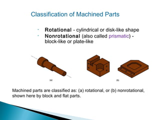
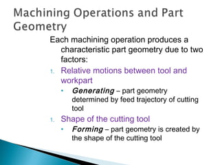
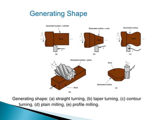
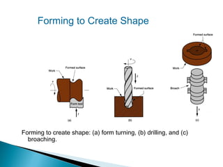
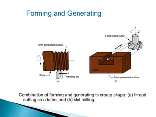
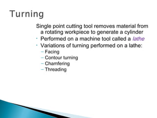
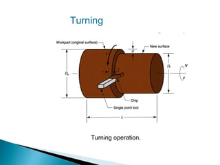
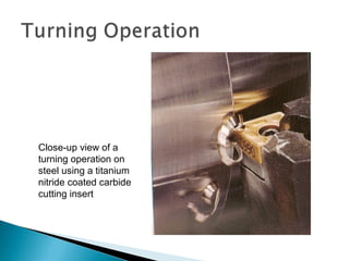
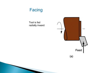
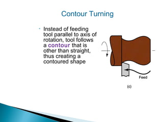
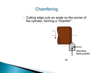
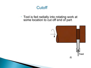
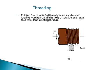
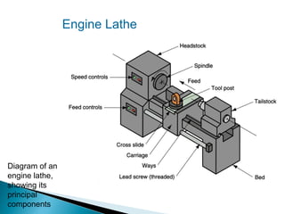
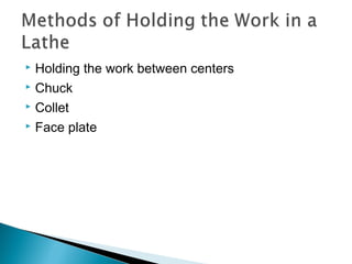
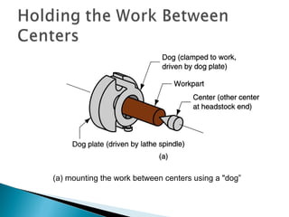
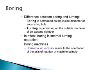
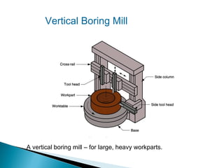
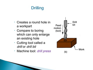
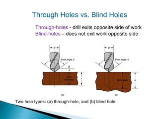
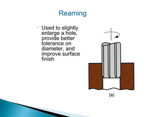
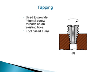
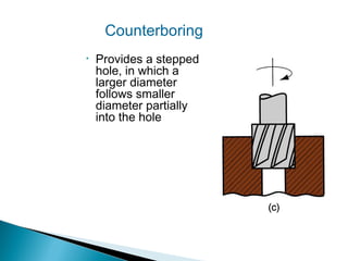
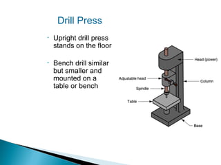
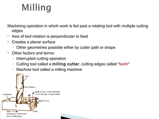
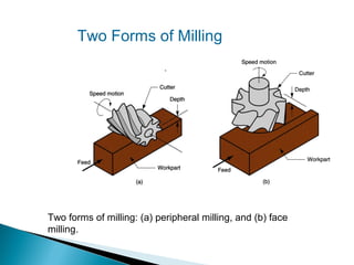
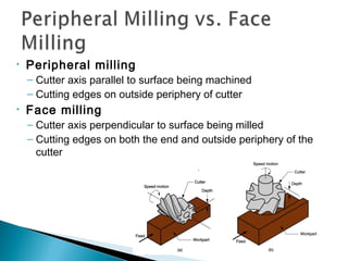
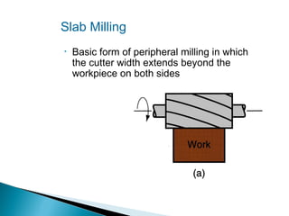
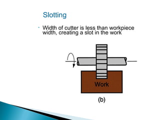
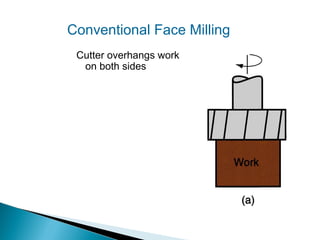
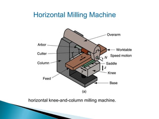
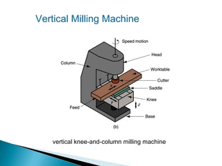
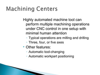
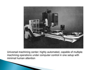
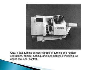
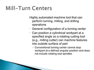
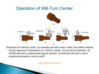
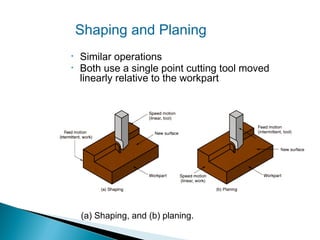
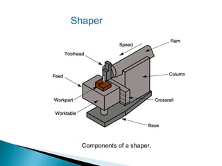
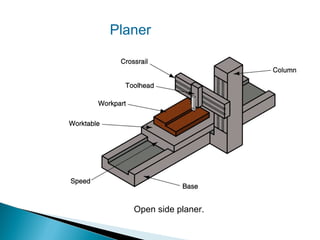
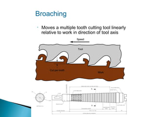
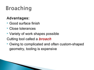
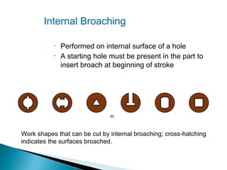
1.
2.
3.
4.
5.
6.

Turning and Related Operations
Drilling and Related Operations
Milling
Machining Centers and Turning Centers
Other Machining Operations
High Speed Machining
A material removal process in which a sharp cutting
tool is used to mechanically cut away material so
that the desired part geometry remains
• Most common application: to shape metal parts
• Most versatile of all manufacturing processes in its
capability to produce a diversity of part geometries
and geometric features with high precision and
accuracy
– Casting can also produce a variety of shapes, but it
lacks the precision and accuracy of machining
Classification of Machined Parts
•
•

Rotational - cylindrical or disk‑like shape
Nonrotational (also called prismatic) block‑like or plate‑like

Machined parts are classified as: (a) rotational, or (b) nonrotational,
shown here by block and flat parts.
Each machining operation produces a
characteristic part geometry due to two
factors:
1. Relative motions between tool and
workpart
•

1.

Generating – part geometry
determined by feed trajectory of cutting
tool

Shape of the cutting tool
•

Forming – part geometry is created by
the shape of the cutting tool
Generating Shape

Generating shape: (a) straight turning, (b) taper turning, (c) contour
turning, (d) plain milling, (e) profile milling.
Forming to Create Shape

Forming to create shape: (a) form turning, (b) drilling, and (c)
broaching.
Forming and Generating

Combination of forming and generating to create shape: (a) thread
cutting on a lathe, and (b) slot milling.
Single point cutting tool removes material from
a rotating workpiece to generate a cylinder
• Performed on a machine tool called a lathe
• Variations of turning performed on a lathe:
– Facing
– Contour turning
– Chamfering
– Threading
Turning

Turning operation.
Close-up view of a
turning operation on
steel using a titanium
nitride coated carbide
cutting insert
Facing
Tool is fed
radially inward
Contour Turning
•

Instead of feeding
tool parallel to axis of
rotation, tool follows
a contour that is
other than straight,
thus creating a
contoured shape
Chamfering
•

Cutting edge cuts an angle on the corner of
the cylinder, forming a "chamfer"
Cutoff
•

Tool is fed radially into rotating work at
some location to cut off end of part
Threading
•

Pointed form tool is fed linearly across surface of
rotating workpart parallel to axis of rotation at a large
feed rate, thus creating threads
Engine Lathe

Diagram of an
engine lathe,
showing its
principal
components
Holding the work between centers
 Chuck
 Collet
 Face plate

(a) mounting the work between centers using a "dog”
(b) three‑jaw chuck
(d) face plate for non‑cylindrical workparts
Tailstock replaced by “turret” that
holds up to six tools
• Tools rapidly brought into action
by indexing the turret
• Tool post replaced by four‑sided
turret to index four tools
• Applications: high production
work that requires a sequence
of cuts on the part
•

Difference between boring and turning:
– Boring is performed on the inside diameter of
an existing hole
– Turning is performed on the outside diameter
of an existing cylinder

•

•

In effect, boring is internal turning
operation
Boring machines
– Horizontal or vertical - refers to the orientation
of the axis of rotation of machine spindle
Vertical Boring Mill

A vertical boring mill – for large, heavy workparts.
Drilling

•

•

•

•

Creates a round hole in
a workpart
Compare to boring
which can only enlarge
an existing hole
Cutting tool called a
drill or drill bit
Machine tool: drill press
Through Holes vs. Blind Holes
Through‑holes - drill exits opposite side of work
Blind‑holes – does not exit work opposite side

Two hole types: (a) through‑hole, and (b) blind hole.
Reaming
•

Used to slightly
enlarge a hole,
provide better
tolerance on
diameter, and
improve surface
finish
Tapping
•

•

Used to provide
internal screw
threads on an
existing hole
Tool called a tap
Counterboring
•

Provides a stepped
hole, in which a
larger diameter
follows smaller
diameter partially
into the hole
Drill Press
•

Upright drill press
stands on the floor

•

Bench drill similar
but smaller and
mounted on a
table or bench
Radial Drill
Large drill
press
designed for
large parts
Machining operation in which work is fed past a rotating tool with multiple cutting
edges
 Axis of tool rotation is perpendicular to feed
 Creates a planar surface
◦ Other geometries possible either by cutter path or shape
 Other factors and terms:
◦ Interrupted cutting operation
◦ Cutting tool called a milling cutter , cutting edges called "teeth"
◦ Machine tool called a milling machine
Two Forms of Milling

Two forms of milling: (a) peripheral milling, and (b) face
milling.
•

Peripheral milling

– Cutter axis parallel to surface being machined
– Cutting edges on outside periphery of cutter

•

Face milling

– Cutter axis perpendicular to surface being milled
– Cutting edges on both the end and outside periphery of the
cutter
Slab Milling
•

Basic form of peripheral milling in which
the cutter width extends beyond the
workpiece on both sides
Slotting
•

Width of cutter is less than workpiece
width, creating a slot in the work
Conventional Face Milling
Cutter overhangs work
on both sides
High speed face
milling using
indexable inserts
End Milling
•

Cutter diameter is
less than work
width, so a slot is
cut into part
Profile Milling
Form of end milling
in which the
outside periphery
of a flat part is cut
Pocket Milling
•

Another form of
end milling
used to mill
shallow
pockets into
flat parts
Surface Contouring
•

Ball‑nose cutter fed
back and forth
across work along a
curvilinear path at
close intervals to
create a three
dimensional surface
form
Horizontal Milling Machine

horizontal knee-and-column milling machine.
Vertical Milling Machine

vertical knee‑and‑column milling machine
Highly automated machine tool can
perform multiple machining operations
under CNC control in one setup with
minimal human attention
◦ Typical operations are milling and drilling
◦ Three, four, or five axes



Other features:

◦ Automatic tool‑changing
◦ Automatic workpart positioning
Universal machining center; highly automated, capable of multiple
machining operations under computer control in one setup with
minimal human attention
CNC 4‑axis turning center; capable of turning and related
operations, contour turning, and automatic tool indexing, all
under computer control.
Highly automated machine tool that can
perform turning, milling, and drilling
operations
• General configuration of a turning center
• Can position a cylindrical workpart at a
specified angle so a rotating cutting tool
(e.g., milling cutter) can machine features
into outside surface of part
– Conventional turning center cannot stop
workpart at a defined angular position and does
not include rotating tool spindles
Operation of Mill-Turn Center

Operation of a mill‑turn center: (a) example part with turned, milled, and drilled surfaces;
and (b) sequence of operations on a mill‑turn center: (1) turn second diameter, (2)
mill flat with part in programmed angular position, (3) drill hole with part in same
programmed position, and (4) cutoff.

Video Mill-Turn Center
Shaping and Planing
•
•

Similar operations
Both use a single point cutting tool moved
linearly relative to the workpart

(a) Shaping, and (b) planing.
A straight, flat surface is created in both
operations
 Interrupted cutting


◦ Subjects tool to impact loading when entering work

Low cutting speeds due to start‑and‑stop motion
 Typical tooling: single point high speed steel tools

Shaper

Components of a shaper.
Planer

Open side planer.
Broaching
•

Moves a multiple tooth cutting tool linearly
relative to work in direction of tool axis
Advantages:
 Good surface finish
 Close tolerances
 Variety of work shapes possible
Cutting tool called a broach
 Owing to complicated and often custom‑shaped
geometry, tooling is expensive
Internal Broaching
•
•

Performed on internal surface of a hole
A starting hole must be present in the part to
insert broach at beginning of stroke

Work shapes that can be cut by internal broaching; cross‑hatching
indicates the surfaces broached.

Machining operations and machine tools

  • 2.
    1. 2. 3. 4. 5. 6. Turning and RelatedOperations Drilling and Related Operations Milling Machining Centers and Turning Centers Other Machining Operations High Speed Machining
  • 3.
    A material removalprocess in which a sharp cutting tool is used to mechanically cut away material so that the desired part geometry remains • Most common application: to shape metal parts • Most versatile of all manufacturing processes in its capability to produce a diversity of part geometries and geometric features with high precision and accuracy – Casting can also produce a variety of shapes, but it lacks the precision and accuracy of machining
  • 4.
    Classification of MachinedParts • • Rotational - cylindrical or disk‑like shape Nonrotational (also called prismatic) block‑like or plate‑like Machined parts are classified as: (a) rotational, or (b) nonrotational, shown here by block and flat parts.
  • 5.
    Each machining operationproduces a characteristic part geometry due to two factors: 1. Relative motions between tool and workpart • 1. Generating – part geometry determined by feed trajectory of cutting tool Shape of the cutting tool • Forming – part geometry is created by the shape of the cutting tool
  • 6.
    Generating Shape Generating shape:(a) straight turning, (b) taper turning, (c) contour turning, (d) plain milling, (e) profile milling.
  • 7.
    Forming to CreateShape Forming to create shape: (a) form turning, (b) drilling, and (c) broaching.
  • 8.
    Forming and Generating Combinationof forming and generating to create shape: (a) thread cutting on a lathe, and (b) slot milling.
  • 9.
    Single point cuttingtool removes material from a rotating workpiece to generate a cylinder • Performed on a machine tool called a lathe • Variations of turning performed on a lathe: – Facing – Contour turning – Chamfering – Threading
  • 10.
  • 11.
    Close-up view ofa turning operation on steel using a titanium nitride coated carbide cutting insert
  • 12.
  • 13.
    Contour Turning • Instead offeeding tool parallel to axis of rotation, tool follows a contour that is other than straight, thus creating a contoured shape
  • 14.
    Chamfering • Cutting edge cutsan angle on the corner of the cylinder, forming a "chamfer"
  • 15.
    Cutoff • Tool is fedradially into rotating work at some location to cut off end of part
  • 16.
    Threading • Pointed form toolis fed linearly across surface of rotating workpart parallel to axis of rotation at a large feed rate, thus creating threads
  • 17.
    Engine Lathe Diagram ofan engine lathe, showing its principal components
  • 18.
    Holding the workbetween centers  Chuck  Collet  Face plate 
  • 19.
    (a) mounting thework between centers using a "dog”
  • 20.
  • 22.
    (d) face platefor non‑cylindrical workparts
  • 23.
    Tailstock replaced by“turret” that holds up to six tools • Tools rapidly brought into action by indexing the turret • Tool post replaced by four‑sided turret to index four tools • Applications: high production work that requires a sequence of cuts on the part
  • 24.
    • Difference between boringand turning: – Boring is performed on the inside diameter of an existing hole – Turning is performed on the outside diameter of an existing cylinder • • In effect, boring is internal turning operation Boring machines – Horizontal or vertical - refers to the orientation of the axis of rotation of machine spindle
  • 25.
    Vertical Boring Mill Avertical boring mill – for large, heavy workparts.
  • 26.
    Drilling • • • • Creates a roundhole in a workpart Compare to boring which can only enlarge an existing hole Cutting tool called a drill or drill bit Machine tool: drill press
  • 27.
    Through Holes vs.Blind Holes Through‑holes - drill exits opposite side of work Blind‑holes – does not exit work opposite side Two hole types: (a) through‑hole, and (b) blind hole.
  • 28.
    Reaming • Used to slightly enlargea hole, provide better tolerance on diameter, and improve surface finish
  • 29.
    Tapping • • Used to provide internalscrew threads on an existing hole Tool called a tap
  • 30.
    Counterboring • Provides a stepped hole,in which a larger diameter follows smaller diameter partially into the hole
  • 31.
    Drill Press • Upright drillpress stands on the floor • Bench drill similar but smaller and mounted on a table or bench
  • 32.
  • 33.
    Machining operation inwhich work is fed past a rotating tool with multiple cutting edges  Axis of tool rotation is perpendicular to feed  Creates a planar surface ◦ Other geometries possible either by cutter path or shape  Other factors and terms: ◦ Interrupted cutting operation ◦ Cutting tool called a milling cutter , cutting edges called "teeth" ◦ Machine tool called a milling machine
  • 34.
    Two Forms ofMilling Two forms of milling: (a) peripheral milling, and (b) face milling.
  • 35.
    • Peripheral milling – Cutteraxis parallel to surface being machined – Cutting edges on outside periphery of cutter • Face milling – Cutter axis perpendicular to surface being milled – Cutting edges on both the end and outside periphery of the cutter
  • 36.
    Slab Milling • Basic formof peripheral milling in which the cutter width extends beyond the workpiece on both sides
  • 37.
    Slotting • Width of cutteris less than workpiece width, creating a slot in the work
  • 38.
    Conventional Face Milling Cutteroverhangs work on both sides
  • 39.
    High speed face millingusing indexable inserts
  • 40.
    End Milling • Cutter diameteris less than work width, so a slot is cut into part
  • 41.
    Profile Milling Form ofend milling in which the outside periphery of a flat part is cut
  • 42.
    Pocket Milling • Another formof end milling used to mill shallow pockets into flat parts
  • 43.
    Surface Contouring • Ball‑nose cutterfed back and forth across work along a curvilinear path at close intervals to create a three dimensional surface form
  • 44.
    Horizontal Milling Machine horizontalknee-and-column milling machine.
  • 45.
    Vertical Milling Machine verticalknee‑and‑column milling machine
  • 46.
    Highly automated machinetool can perform multiple machining operations under CNC control in one setup with minimal human attention ◦ Typical operations are milling and drilling ◦ Three, four, or five axes  Other features: ◦ Automatic tool‑changing ◦ Automatic workpart positioning
  • 47.
    Universal machining center;highly automated, capable of multiple machining operations under computer control in one setup with minimal human attention
  • 48.
    CNC 4‑axis turningcenter; capable of turning and related operations, contour turning, and automatic tool indexing, all under computer control.
  • 49.
    Highly automated machinetool that can perform turning, milling, and drilling operations • General configuration of a turning center • Can position a cylindrical workpart at a specified angle so a rotating cutting tool (e.g., milling cutter) can machine features into outside surface of part – Conventional turning center cannot stop workpart at a defined angular position and does not include rotating tool spindles
  • 50.
    Operation of Mill-TurnCenter Operation of a mill‑turn center: (a) example part with turned, milled, and drilled surfaces; and (b) sequence of operations on a mill‑turn center: (1) turn second diameter, (2) mill flat with part in programmed angular position, (3) drill hole with part in same programmed position, and (4) cutoff. Video Mill-Turn Center
  • 51.
    Shaping and Planing • • Similaroperations Both use a single point cutting tool moved linearly relative to the workpart (a) Shaping, and (b) planing.
  • 52.
    A straight, flatsurface is created in both operations  Interrupted cutting  ◦ Subjects tool to impact loading when entering work Low cutting speeds due to start‑and‑stop motion  Typical tooling: single point high speed steel tools 
  • 53.
  • 54.
  • 55.
    Broaching • Moves a multipletooth cutting tool linearly relative to work in direction of tool axis
  • 56.
    Advantages:  Good surfacefinish  Close tolerances  Variety of work shapes possible Cutting tool called a broach  Owing to complicated and often custom‑shaped geometry, tooling is expensive
  • 57.
    Internal Broaching • • Performed oninternal surface of a hole A starting hole must be present in the part to insert broach at beginning of stroke Work shapes that can be cut by internal broaching; cross‑hatching indicates the surfaces broached.

Editor's Notes

  • #16 It is also called as parting or grooving
  • #23 Faceplate is a circular metal (usually cast iron) plate which fixes to the end of the lathe spindle. The workpiece is then clamped to the faceplate, typically using t-nuts in slots in the faceplate, or less commonly threaded holes in the faceplate itself