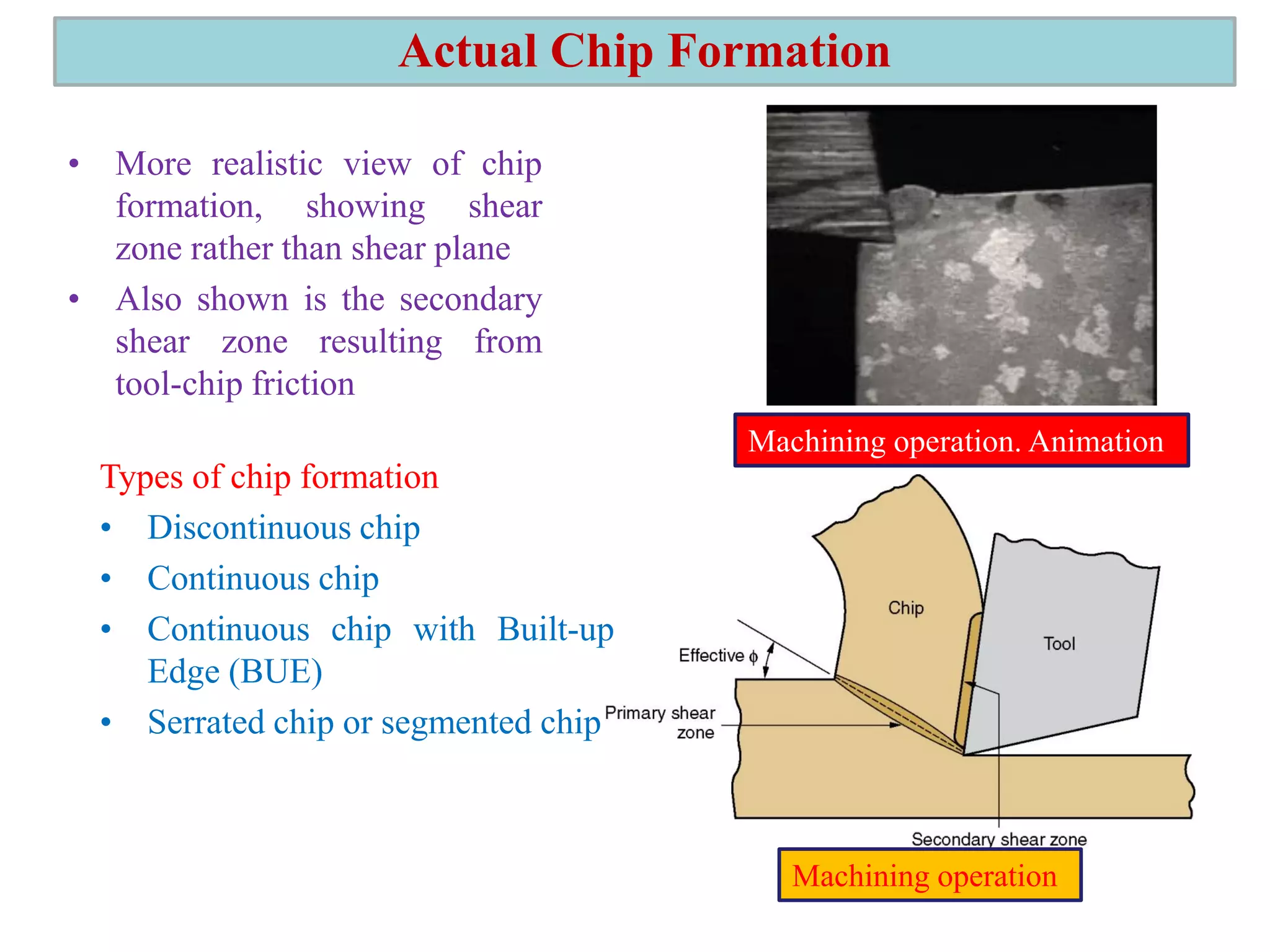
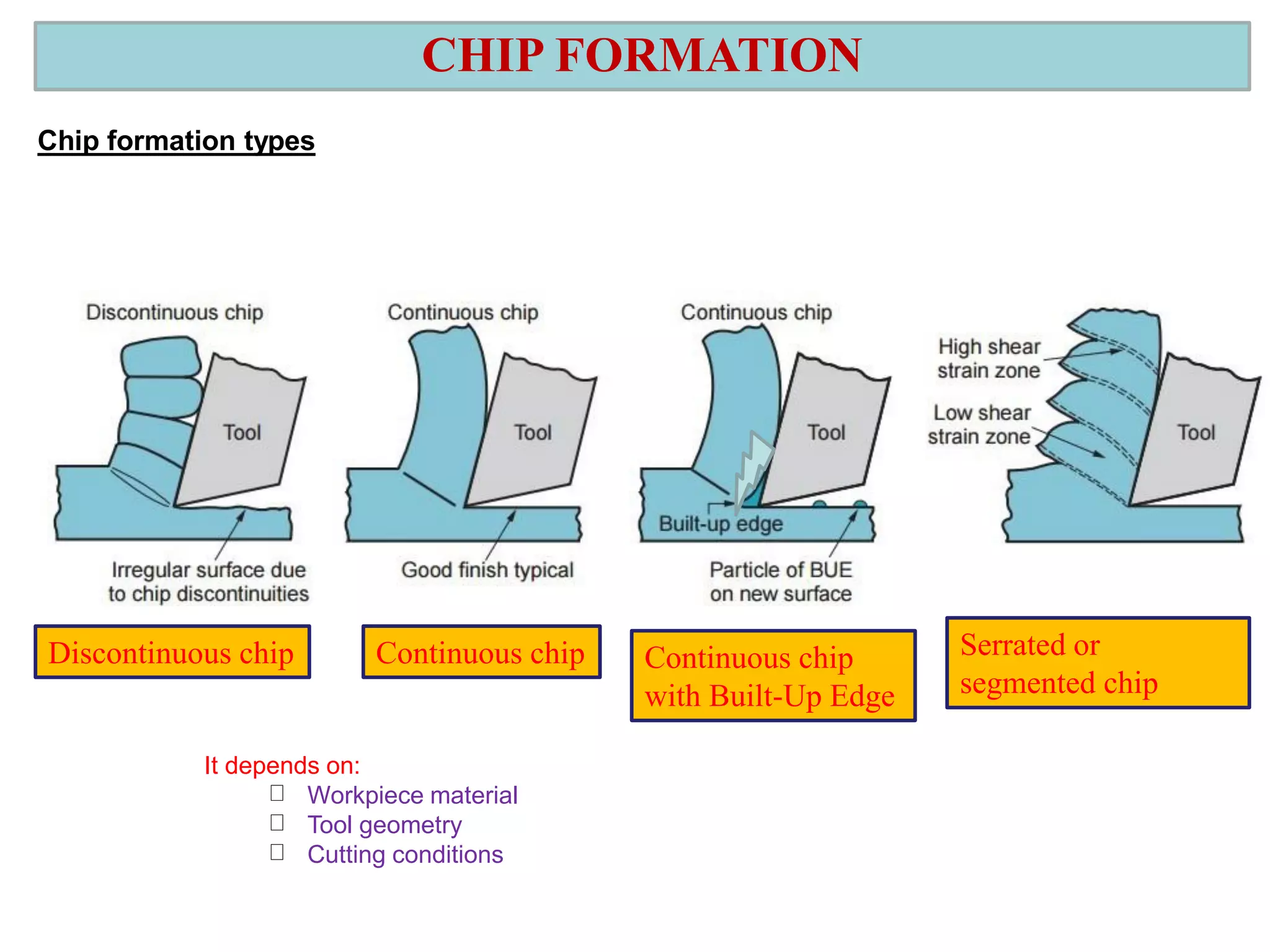
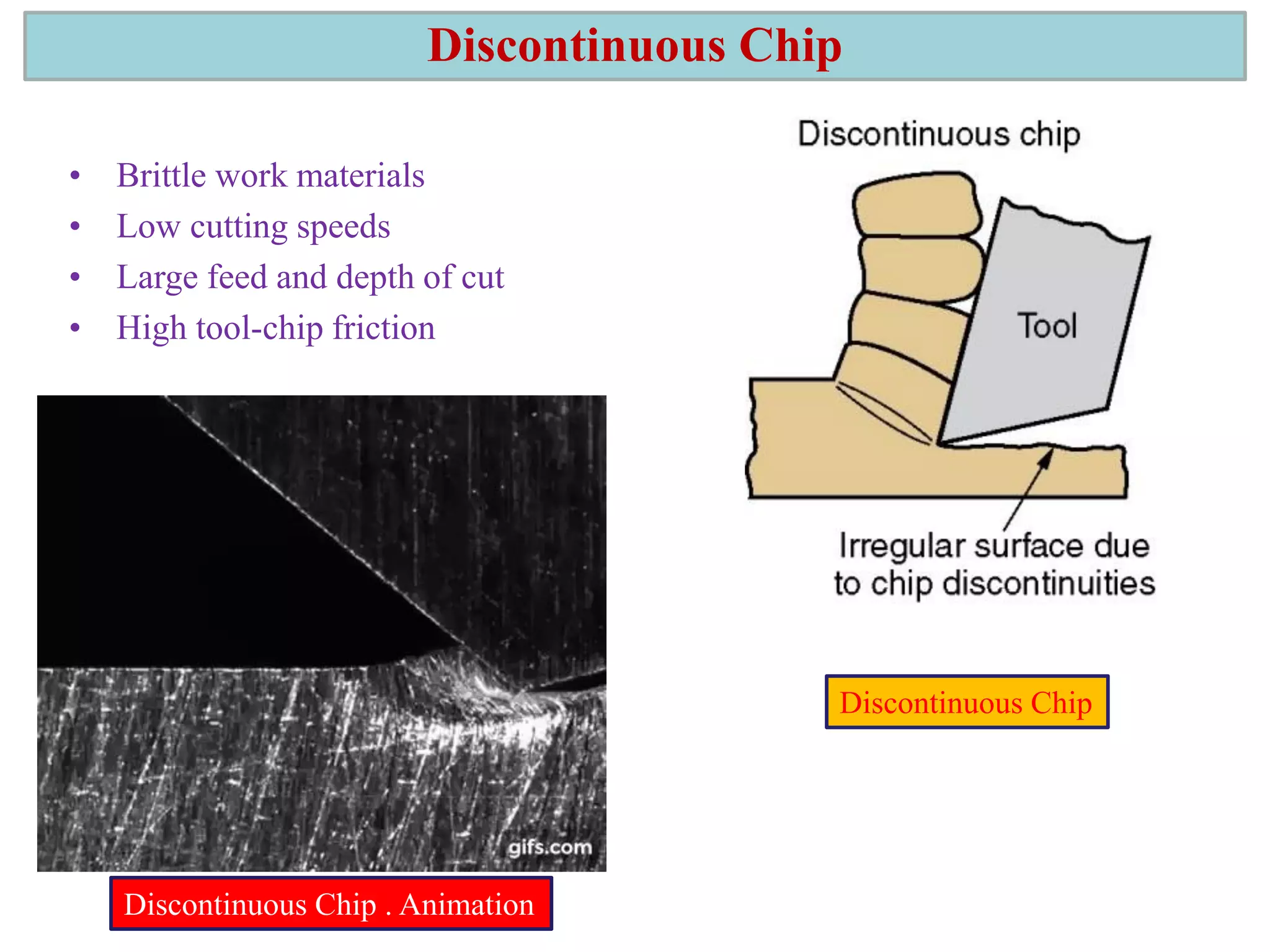
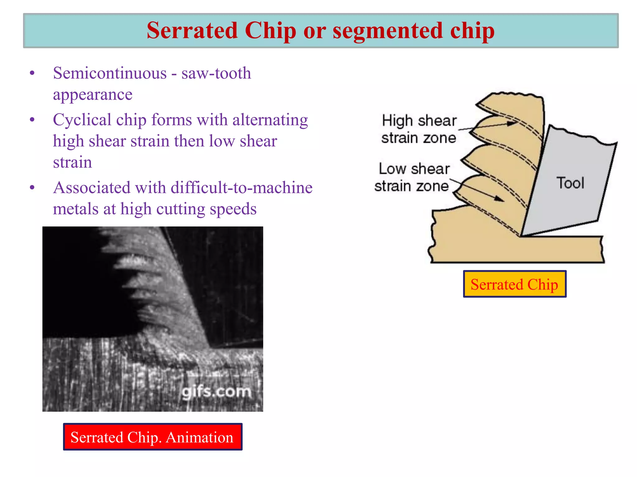
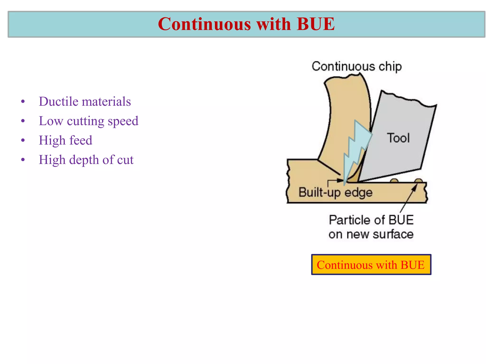
1. The document discusses different types of chip formation including discontinuous, continuous, and serrated chips, which depend on factors like workpiece material and cutting conditions.
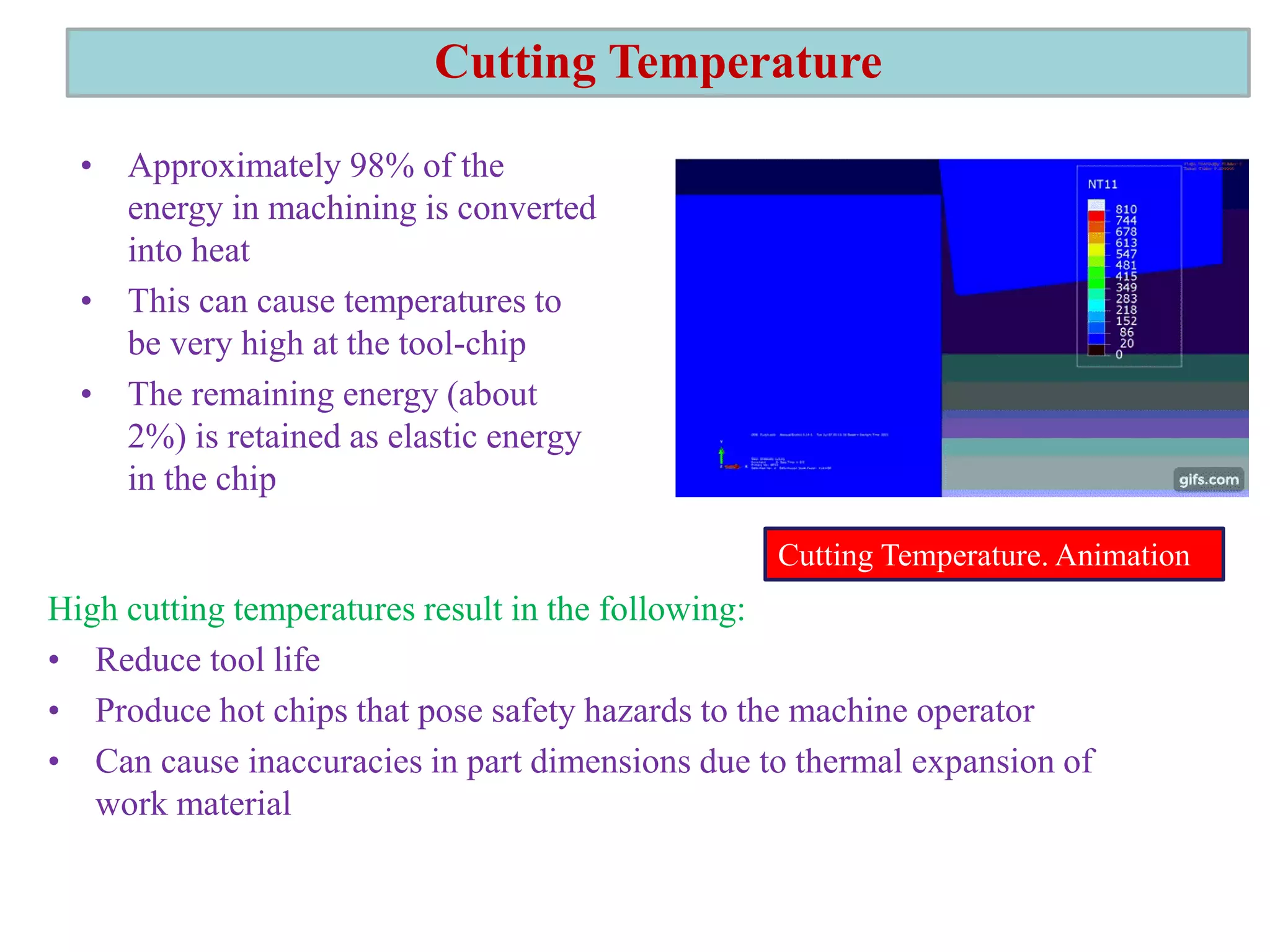
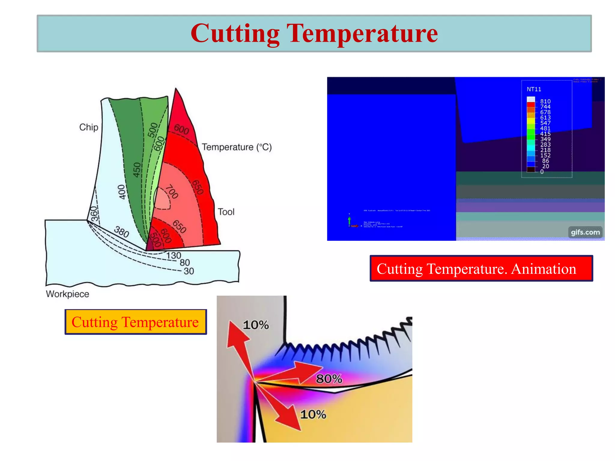
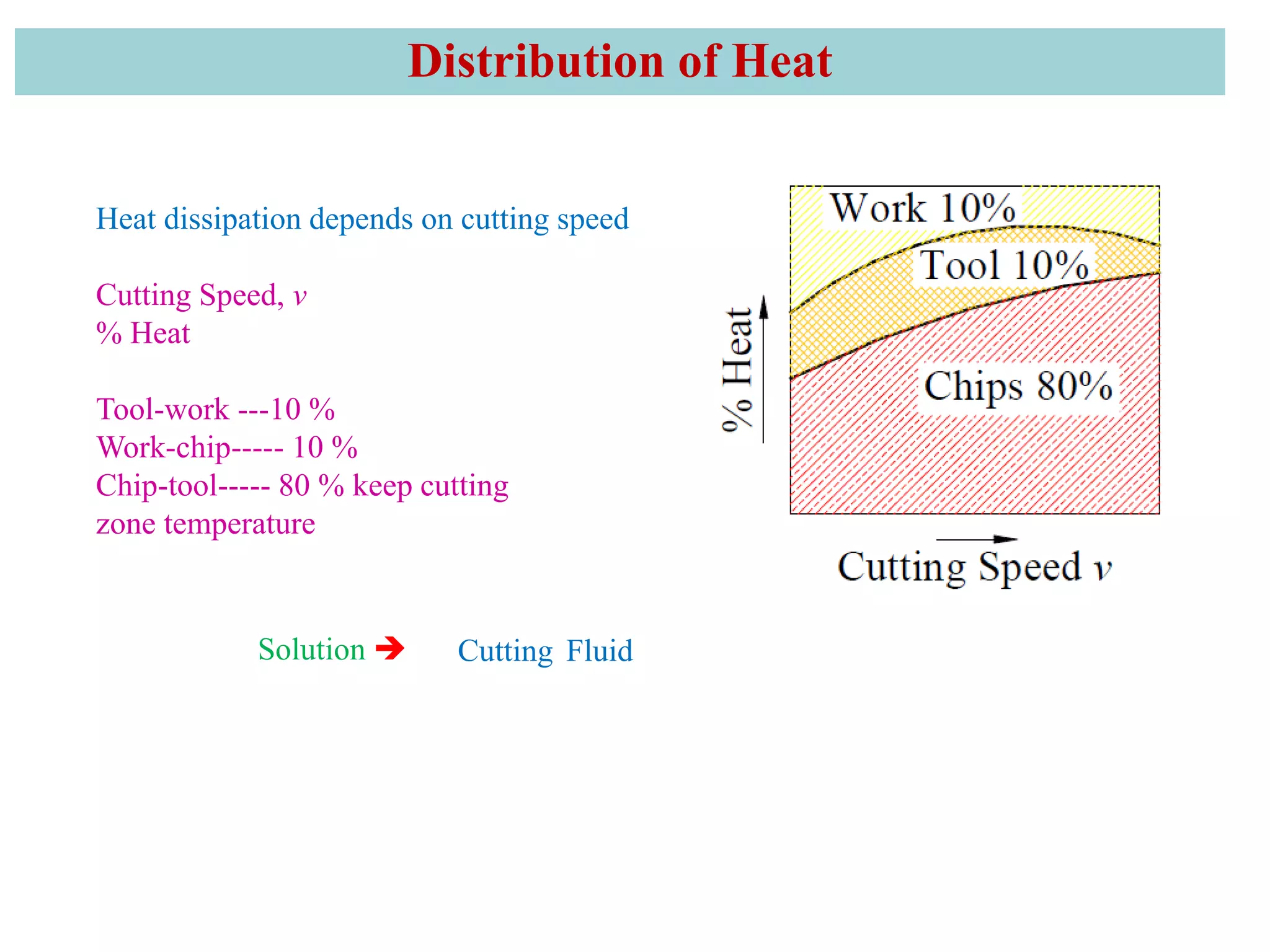
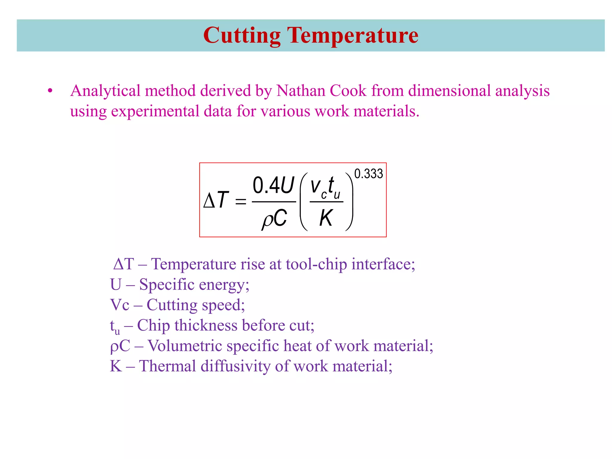
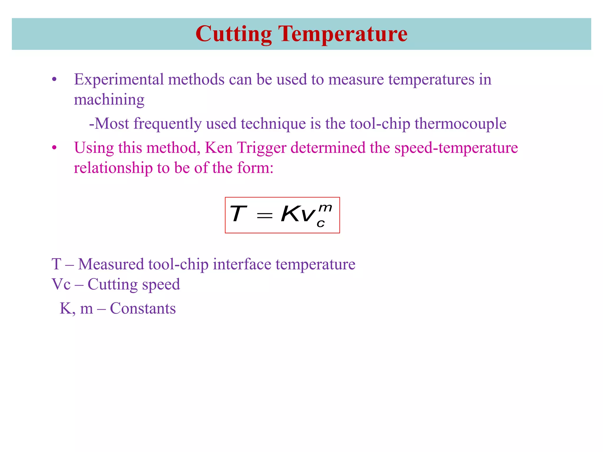
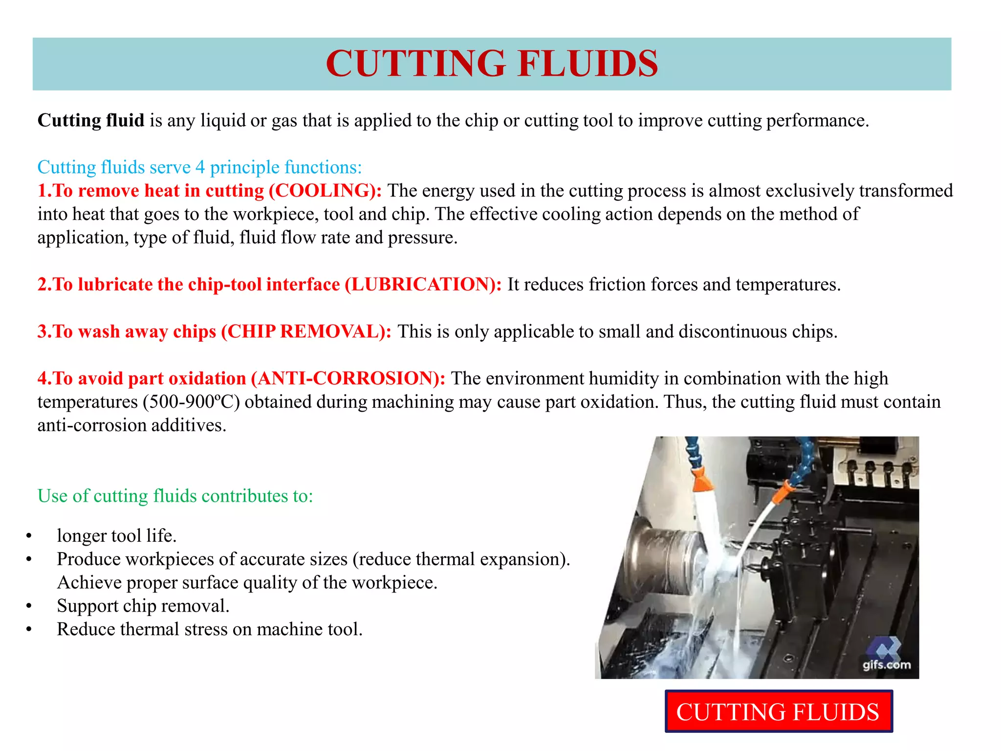
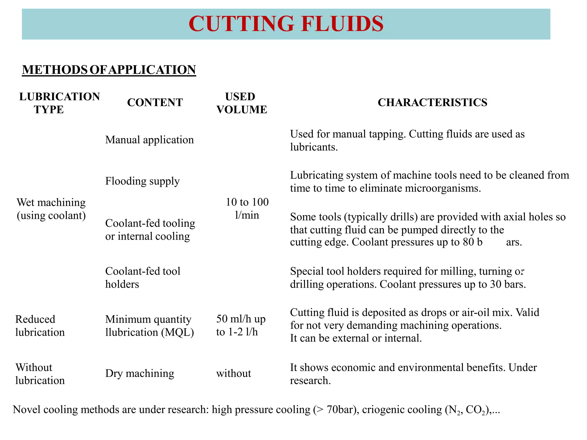
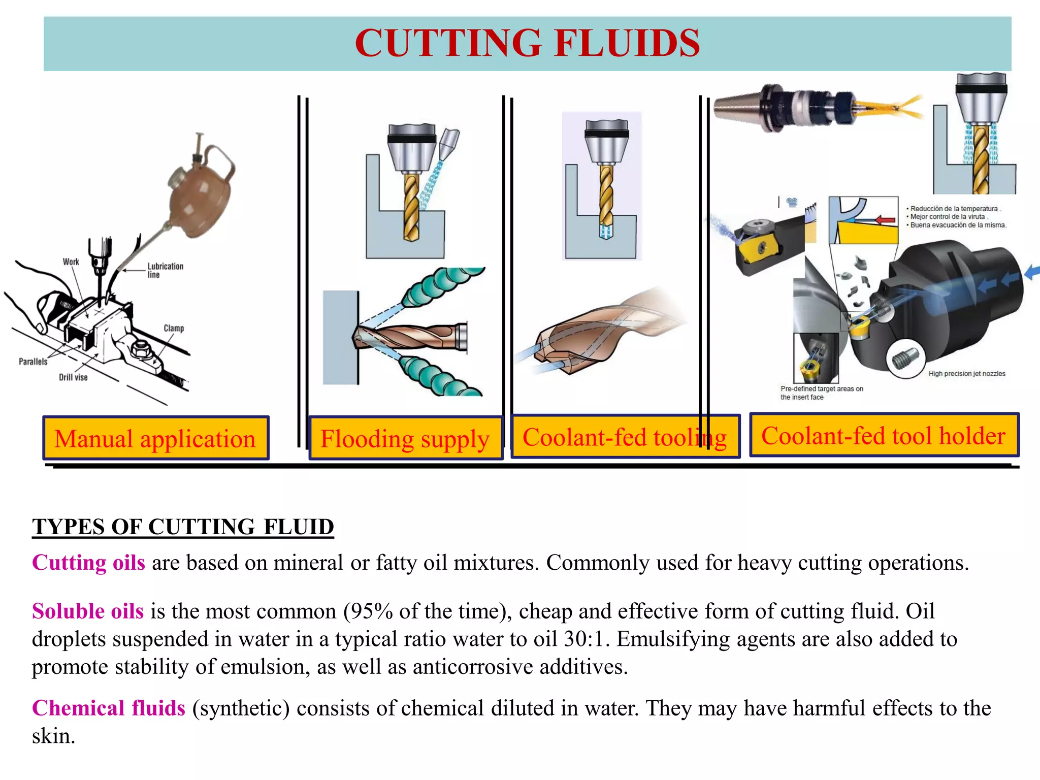
2. It also covers cutting temperature, how most of the energy from machining is converted to heat, and how high temperatures can reduce tool life. Cutting fluids are discussed as a way to reduce cutting temperature.
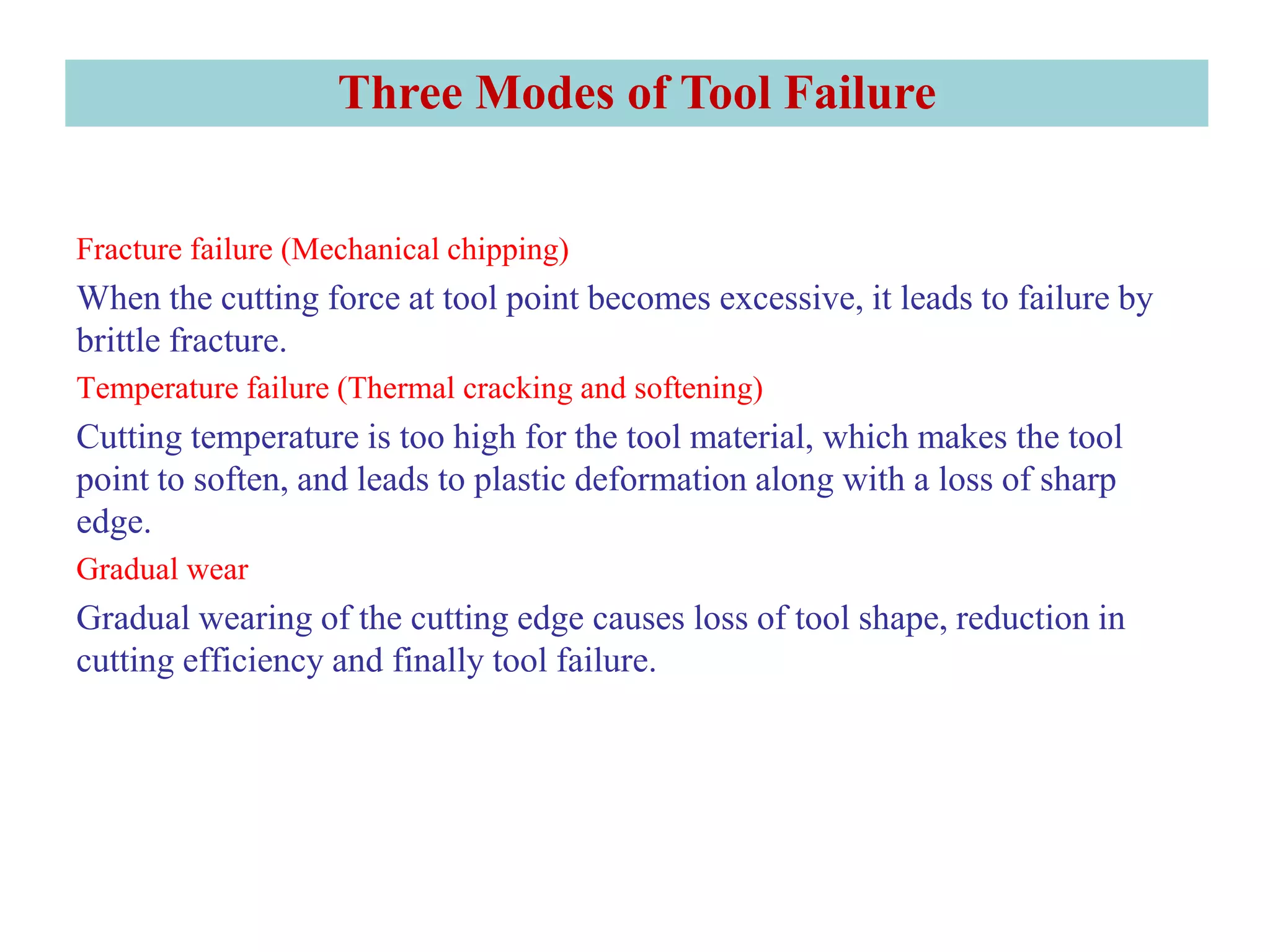
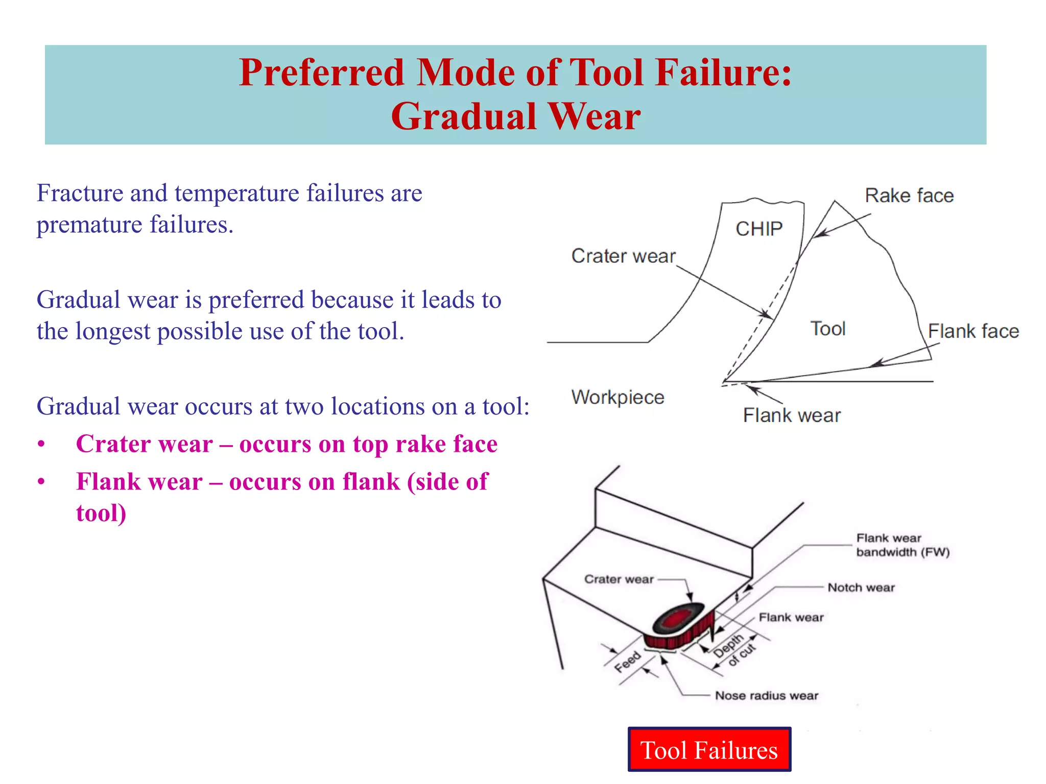
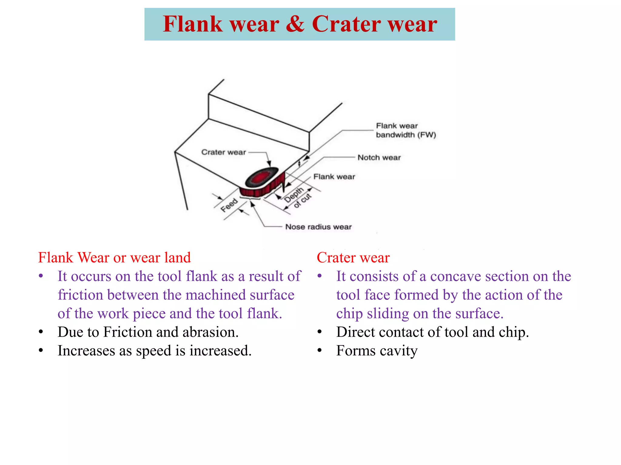
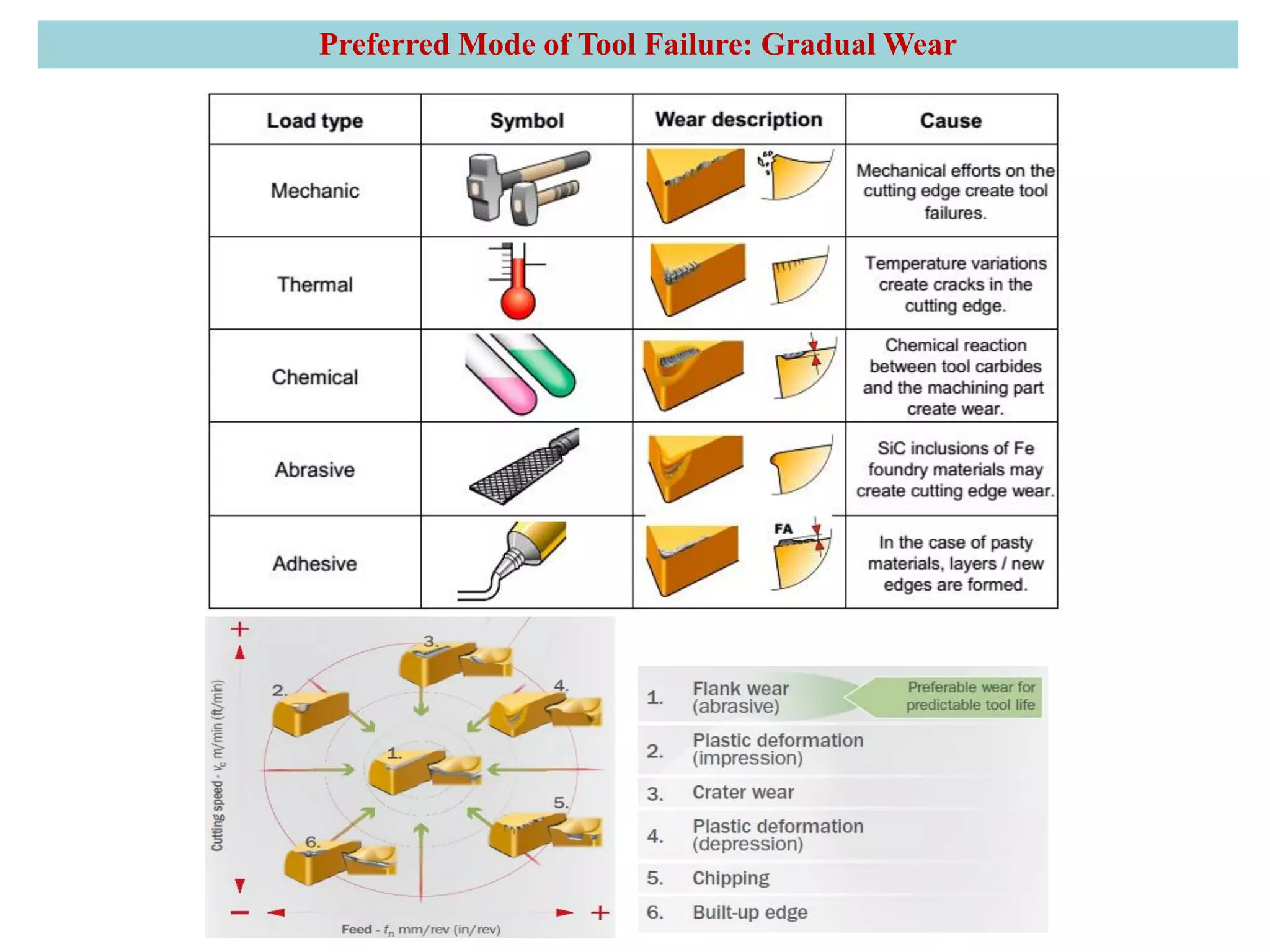
3. The three main types of tool failure are fracture, temperature-related, and gradual wear, with gradual wear being the preferred mode since it leads to the longest tool life. Flank and crater wear are described as two areas where gradual wear occurs.