Downloaded 238 times

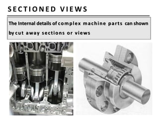
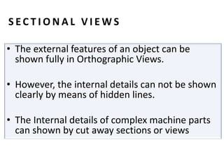
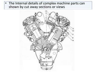
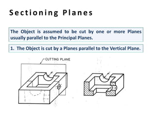
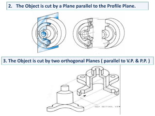

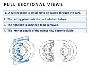

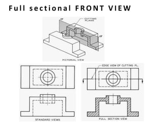
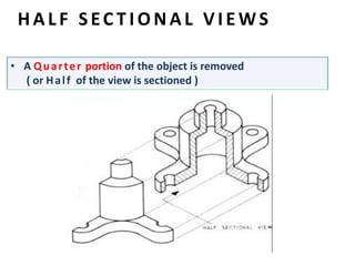
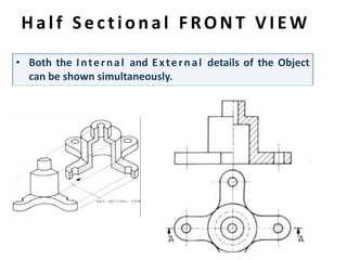

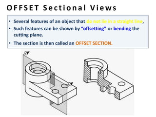
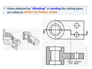
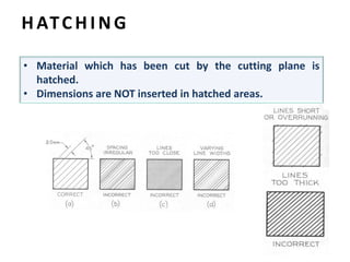
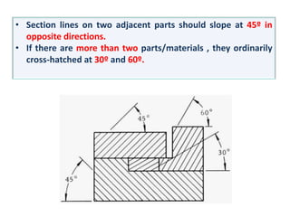
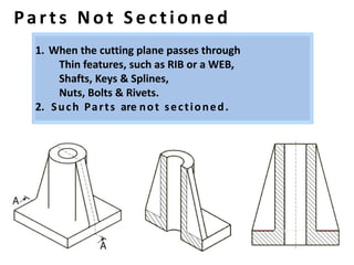
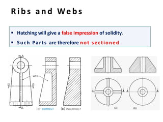

The document discusses sectional views, which show internal details of objects by cutting away portions. There are three main types of sectional views: full sectional views, which cut the object completely; half sectional views, which cut away half the object; and offset sectional views, which cut on an angle. Hatched lines are used to indicate cut-away areas. Dimension lines are not placed in hatched regions.


