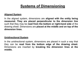
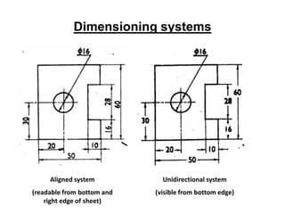
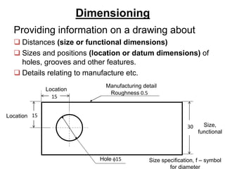
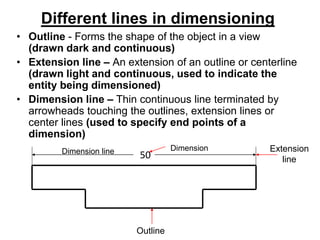
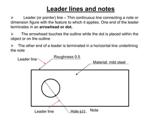
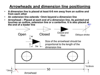
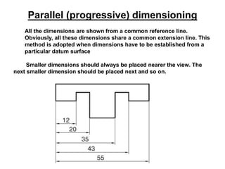
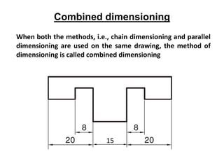
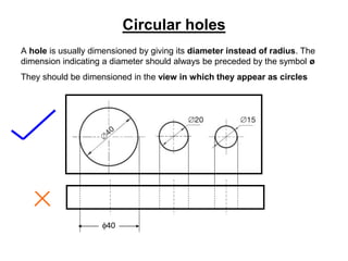
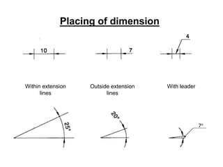
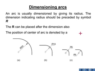
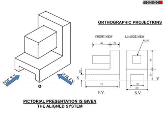
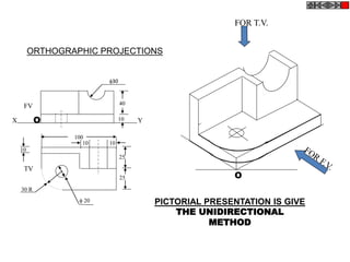
Shree S’ad Vidya Mandal
Institute Of Technology
ENGINEERING GRAPHICS
Branch: - Mechanical – 02
Group :- 01
Guided Name:-
 Topic : - All Dimensioning system.
Prepared By : -
1. DHAVAL S. PATEL. 63
2. DHRUMIL J. PATEL . 64
3. HARSH J. PATEL. 65
4. JAY J. PATEL. 66
Aligned System
In the aligned system, dimensions are aligned with the entity being
measured. They are placed perpendicular to the dimension line
such that they may be read from the bottom or right-hand side of the
drawing sheet. Dimensions are placed at the middle and on top of the
dimension lines.
Unidirectional System
In the unidirectional system, dimensions are placed in such a way that
they can be read from the bottom edge of the drawing sheet.
Dimensions are inserted by breaking the dimension lines at the
middle.
Systems of Dimensioning
Dimensioning systems
Aligned system
(readable from bottom and
right edge of sheet)
Unidirectional system
(visible from bottom edge)
Dimensioning
Providing information on a drawing about
 Distances (size or functional dimensions)
 Sizes and positions (location or datum dimensions) of
holes, grooves and other features.
 Details relating to manufacture etc.
15
15
30
Roughness 0.5
Location
Location
Size,
functional
Manufacturing detail
Hole f15 Size specification, f – symbol
for diameter
Different lines in dimensioning
• Outline - Forms the shape of the object in a view
(drawn dark and continuous)
• Extension line – An extension of an outline or centerline
(drawn light and continuous, used to indicate the
entity being dimensioned)
• Dimension line – Thin continuous line terminated by
arrowheads touching the outlines, extension lines or
center lines (used to specify end points of a
dimension)
Outline
Extension
line50Dimension line Dimension
Leader lines and notes
Hole f15 Note
 Leader (or pointer) line – Thin continuous line connecting a note or
dimension figure with the feature to which it applies. One end of the leader
terminates in an arrowhead or dot.
 The arrowhead touches the outline while the dot is placed within the
object or on the outline
 The other end of a leader is terminated in a horizontal line underlining
the note
Leader line
Material: mild steel
Roughness 0.5
Leader line
Arrowheads and dimension line positioning
• A dimension line is placed at least 6-8 mm away from an outline and
from each other
• An extension line extends ~3mm beyond a dimension line
• Arrowhead – Placed at each end of a dimension line, its pointed end
touches an outline, extension line or a centerline. It is also placed at
the end of a leader line
~3mm 50
Arrowhead
45o
Open Closed
Closed and
filled Oblique stroke
w
3w
Size of the arrowhead should be
proportional to the length of the
dimension line
~6-8mm
Chain (continuous) dimensioning
All the dimensions are aligned in such a way that an arrowhead of one
dimension touches tip-to-tip the arrowhead of the adjacent dimension. The
overall dimension is placed outside the other smaller dimensions
Parallel (progressive) dimensioning
All the dimensions are shown from a common reference line.
Obviously, all these dimensions share a common extension line. This
method is adopted when dimensions have to be established from a
particular datum surface
Smaller dimensions should always be placed nearer the view. The
next smaller dimension should be placed next and so on.
Combined dimensioning
When both the methods, i.e., chain dimensioning and parallel
dimensioning are used on the same drawing, the method of
dimensioning is called combined dimensioning
15
Circular holes
A hole is usually dimensioned by giving its diameter instead of radius. The
dimension indicating a diameter should always be preceded by the symbol ø
They should be dimensioned in the view in which they appear as circles
f40
Placing of dimension
Within extension
lines
Outside extension
lines
With leader
7o
An arc is usually dimensioned by giving its radius. The
dimension indicating radius should be preceded by symbol
R
The R can be placed after the dimension also
The position of center of arc is denoted by a
Dimensioning arcs
O
PICTORIAL PRESENTATION IS GIVEN
THE ALIGNED SYSTEM
ORTHOGRAPHIC PROJECTIONS
X Y
40 20
SQ30
2050
60
30
10
F.V. S.V.
FRONT VIEW L.H.SIDE VIEW
75
O
PICTORIAL PRESENTATION IS GIVE
THE UNIDIRECTIONAL
METHOD
ORTHOGRAPHIC PROJECTIONS
FOR T.V.
X Y
FV
O
40
10
10
TV
25
25
30 R
100
1010
f 20
f30
All dimensioning system

All dimensioning system

  • 1.
    Shree S’ad VidyaMandal Institute Of Technology ENGINEERING GRAPHICS Branch: - Mechanical – 02 Group :- 01 Guided Name:-  Topic : - All Dimensioning system. Prepared By : - 1. DHAVAL S. PATEL. 63 2. DHRUMIL J. PATEL . 64 3. HARSH J. PATEL. 65 4. JAY J. PATEL. 66
  • 2.
    Aligned System In thealigned system, dimensions are aligned with the entity being measured. They are placed perpendicular to the dimension line such that they may be read from the bottom or right-hand side of the drawing sheet. Dimensions are placed at the middle and on top of the dimension lines. Unidirectional System In the unidirectional system, dimensions are placed in such a way that they can be read from the bottom edge of the drawing sheet. Dimensions are inserted by breaking the dimension lines at the middle. Systems of Dimensioning
  • 3.
    Dimensioning systems Aligned system (readablefrom bottom and right edge of sheet) Unidirectional system (visible from bottom edge)
  • 4.
    Dimensioning Providing information ona drawing about  Distances (size or functional dimensions)  Sizes and positions (location or datum dimensions) of holes, grooves and other features.  Details relating to manufacture etc. 15 15 30 Roughness 0.5 Location Location Size, functional Manufacturing detail Hole f15 Size specification, f – symbol for diameter
  • 5.
    Different lines indimensioning • Outline - Forms the shape of the object in a view (drawn dark and continuous) • Extension line – An extension of an outline or centerline (drawn light and continuous, used to indicate the entity being dimensioned) • Dimension line – Thin continuous line terminated by arrowheads touching the outlines, extension lines or center lines (used to specify end points of a dimension) Outline Extension line50Dimension line Dimension
  • 6.
    Leader lines andnotes Hole f15 Note  Leader (or pointer) line – Thin continuous line connecting a note or dimension figure with the feature to which it applies. One end of the leader terminates in an arrowhead or dot.  The arrowhead touches the outline while the dot is placed within the object or on the outline  The other end of a leader is terminated in a horizontal line underlining the note Leader line Material: mild steel Roughness 0.5 Leader line
  • 7.
    Arrowheads and dimensionline positioning • A dimension line is placed at least 6-8 mm away from an outline and from each other • An extension line extends ~3mm beyond a dimension line • Arrowhead – Placed at each end of a dimension line, its pointed end touches an outline, extension line or a centerline. It is also placed at the end of a leader line ~3mm 50 Arrowhead 45o Open Closed Closed and filled Oblique stroke w 3w Size of the arrowhead should be proportional to the length of the dimension line ~6-8mm
  • 8.
    Chain (continuous) dimensioning Allthe dimensions are aligned in such a way that an arrowhead of one dimension touches tip-to-tip the arrowhead of the adjacent dimension. The overall dimension is placed outside the other smaller dimensions
  • 9.
    Parallel (progressive) dimensioning Allthe dimensions are shown from a common reference line. Obviously, all these dimensions share a common extension line. This method is adopted when dimensions have to be established from a particular datum surface Smaller dimensions should always be placed nearer the view. The next smaller dimension should be placed next and so on.
  • 10.
    Combined dimensioning When boththe methods, i.e., chain dimensioning and parallel dimensioning are used on the same drawing, the method of dimensioning is called combined dimensioning 15
  • 11.
    Circular holes A holeis usually dimensioned by giving its diameter instead of radius. The dimension indicating a diameter should always be preceded by the symbol ø They should be dimensioned in the view in which they appear as circles f40
  • 12.
    Placing of dimension Withinextension lines Outside extension lines With leader 7o
  • 13.
    An arc isusually dimensioned by giving its radius. The dimension indicating radius should be preceded by symbol R The R can be placed after the dimension also The position of center of arc is denoted by a Dimensioning arcs
  • 14.
    O PICTORIAL PRESENTATION ISGIVEN THE ALIGNED SYSTEM ORTHOGRAPHIC PROJECTIONS X Y 40 20 SQ30 2050 60 30 10 F.V. S.V. FRONT VIEW L.H.SIDE VIEW 75
  • 15.
    O PICTORIAL PRESENTATION ISGIVE THE UNIDIRECTIONAL METHOD ORTHOGRAPHIC PROJECTIONS FOR T.V. X Y FV O 40 10 10 TV 25 25 30 R 100 1010 f 20 f30