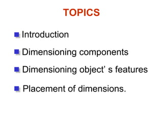
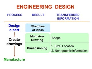
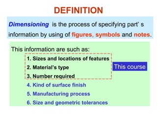
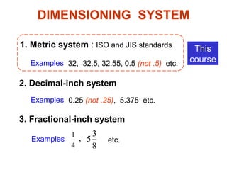
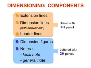
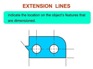
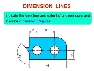
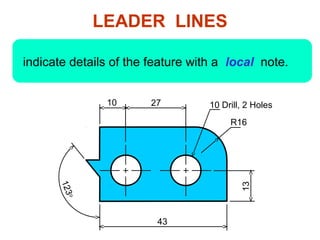
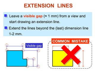
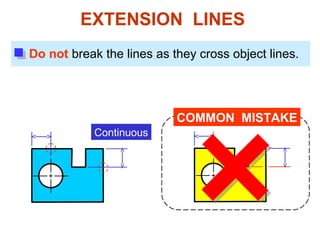
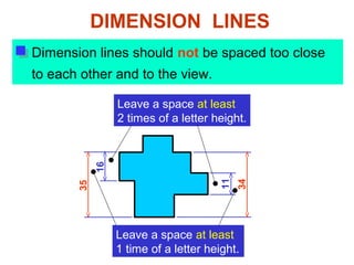
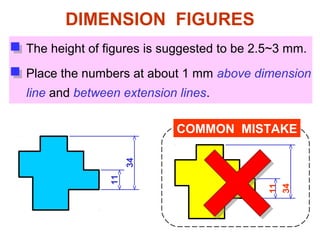
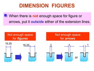
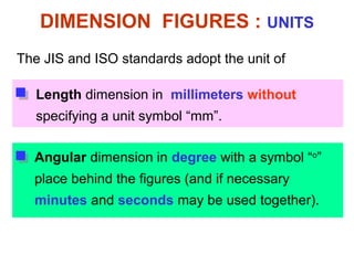
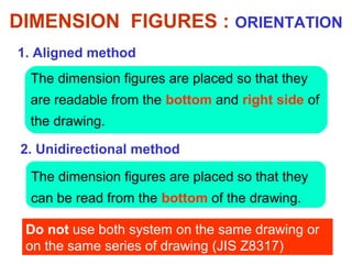
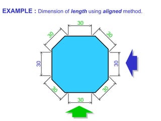
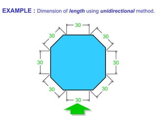
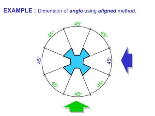
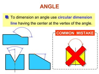
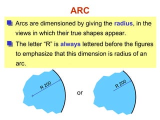
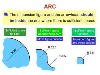
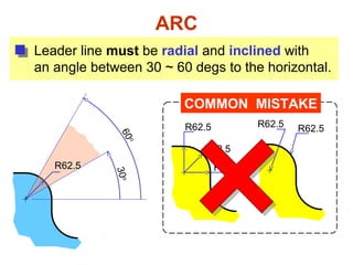
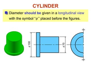
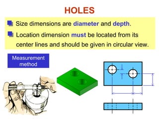
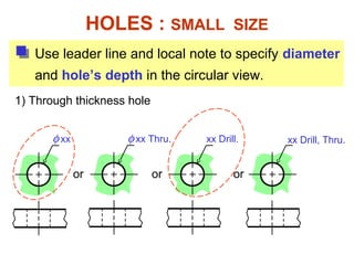
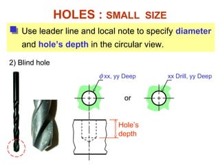
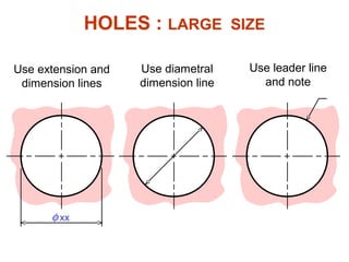
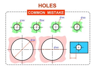
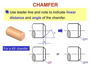
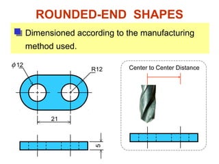
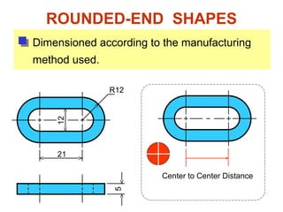
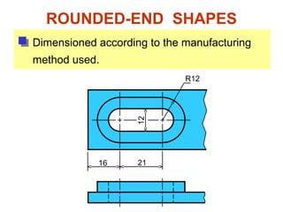
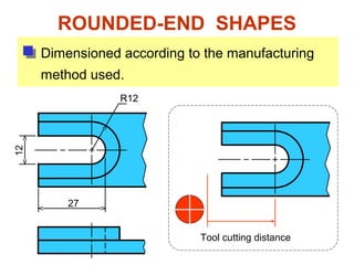
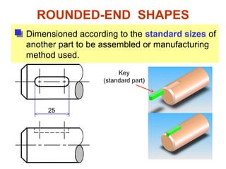
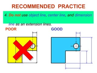
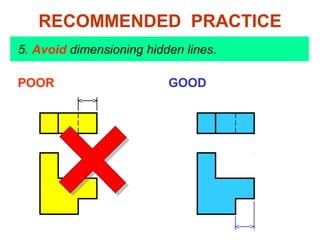
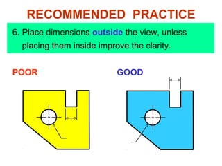
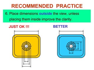
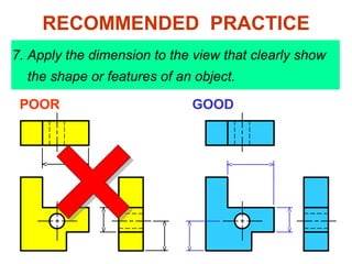
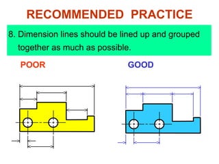
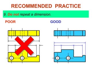
This document discusses dimensioning practices for engineering drawings. It begins by defining dimensioning as specifying part sizes, locations, materials, tolerances and other information using figures, symbols and notes. It then covers components of dimensioning like extension lines, dimension lines, leader lines and dimension figures. Specific guidelines are provided for dimensioning different geometric features such as angles, arcs, cylinders, holes, chamfers and rounded shapes. The document concludes with recommendations for placement of dimensions on drawings.
Basics of engineering drawing by Rishabh NatholiaRISHABH NATHOLIA
This is my work to make sure it is easy to understand the basic of Mechanical Engineer Drawing.It is a made for all and a quick bite to the very basics of engineering drawing. This data will also help the students to score more in their subjects. This will also help on design sector interviews.
Download link: https://www.researchgate.net/publication/318852873_Engineering_Drawing_-_I
DOI: 10.13140/RG.2.2.22512.56328
An engineering drawing is a type of technical drawing, used to fully and clearly define requirements for engineered items, and is usually created in accordance with standardized conventions for layout, nomenclature, interpretation, appearance size, etc.
Its purpose is to accurately and unambiguously capture all the geometric features of a product or a component. The end goal of an engineering drawing is to convey all the required information that will allow a manufacturer to produce that component.
this is an essential originally power point created notes in section view of engineering graphics and drawing hope you enjoy this and take its benefits....
Detail drawings completely describe a single part with multiview orthographic projections.
Should provide all the information necessary to economically manufacture a high quality part.
Overview of the fundamental roles in Hydropower generation and the components involved in wider Electrical Engineering.
This paper presents the design and construction of hydroelectric dams from the hydrologist’s survey of the valley before construction, all aspects and involved disciplines, fluid dynamics, structural engineering, generation and mains frequency regulation to the very transmission of power through the network in the United Kingdom.
Author: Robbie Edward Sayers
Collaborators and co editors: Charlie Sims and Connor Healey.
(C) 2024 Robbie E. Sayers
Water scarcity is the lack of fresh water resources to meet the standard water demand. There are two type of water scarcity. One is physical. The other is economic water scarcity.
Hybrid optimization of pumped hydro system and solar- Engr. Abdul-Azeez.pdffxintegritypublishin
Advancements in technology unveil a myriad of electrical and electronic breakthroughs geared towards efficiently harnessing limited resources to meet human energy demands. The optimization of hybrid solar PV panels and pumped hydro energy supply systems plays a pivotal role in utilizing natural resources effectively. This initiative not only benefits humanity but also fosters environmental sustainability. The study investigated the design optimization of these hybrid systems, focusing on understanding solar radiation patterns, identifying geographical influences on solar radiation, formulating a mathematical model for system optimization, and determining the optimal configuration of PV panels and pumped hydro storage. Through a comparative analysis approach and eight weeks of data collection, the study addressed key research questions related to solar radiation patterns and optimal system design. The findings highlighted regions with heightened solar radiation levels, showcasing substantial potential for power generation and emphasizing the system's efficiency. Optimizing system design significantly boosted power generation, promoted renewable energy utilization, and enhanced energy storage capacity. The study underscored the benefits of optimizing hybrid solar PV panels and pumped hydro energy supply systems for sustainable energy usage. Optimizing the design of solar PV panels and pumped hydro energy supply systems as examined across diverse climatic conditions in a developing country, not only enhances power generation but also improves the integration of renewable energy sources and boosts energy storage capacities, particularly beneficial for less economically prosperous regions. Additionally, the study provides valuable insights for advancing energy research in economically viable areas. Recommendations included conducting site-specific assessments, utilizing advanced modeling tools, implementing regular maintenance protocols, and enhancing communication among system components.
Welcome to WIPAC Monthly the magazine brought to you by the LinkedIn Group Water Industry Process Automation & Control.
In this month's edition, along with this month's industry news to celebrate the 13 years since the group was created we have articles including
A case study of the used of Advanced Process Control at the Wastewater Treatment works at Lleida in Spain
A look back on an article on smart wastewater networks in order to see how the industry has measured up in the interim around the adoption of Digital Transformation in the Water Industry.
Final project report on grocery store management system..pdfKamal Acharya
In today’s fast-changing business environment, it’s extremely important to be able to respond to client needs in the most effective and timely manner. If your customers wish to see your business online and have instant access to your products or services.
Online Grocery Store is an e-commerce website, which retails various grocery products. This project allows viewing various products available enables registered users to purchase desired products instantly using Paytm, UPI payment processor (Instant Pay) and also can place order by using Cash on Delivery (Pay Later) option. This project provides an easy access to Administrators and Managers to view orders placed using Pay Later and Instant Pay options.
In order to develop an e-commerce website, a number of Technologies must be studied and understood. These include multi-tiered architecture, server and client-side scripting techniques, implementation technologies, programming language (such as PHP, HTML, CSS, JavaScript) and MySQL relational databases. This is a project with the objective to develop a basic website where a consumer is provided with a shopping cart website and also to know about the technologies used to develop such a website.
This document will discuss each of the underlying technologies to create and implement an e- commerce website.
5. DEFINITION
Dimensioning is the process of specifying part’ s
information by using of figures, symbols and notes.
This information are such as:
1. Sizes and locations of features
2. Material’s type
3. Number required
4. Kind of surface finish
5. Manufacturing process
6. Size and geometric tolerances
This course
6. DIMENSIONING SYSTEM
4
1
1. Metric system : ISO and JIS standards
2. Decimal-inch system
3. Fractional-inch system
8
3
5,
0.25 (not .25), 5.375 etc.Examples
Examples
32, 32.5, 32.55, 0.5 (not .5) etc.Examples
etc.
This
course
13. EXTENSION LINES
Leave a visible gap (≈ 1 mm) from a view and
start drawing an extension line.
Extend the lines beyond the (last) dimension line
1-2 mm.
Visible gap
COMMON MISTAKE
14. Do not break the lines as they cross object lines.
COMMON MISTAKE
Continuous
EXTENSION LINES
15. Dimension lines should not be spaced too close
to each other and to the view.
11
34
Leave a space at least
2 times of a letter height.
16
35
DIMENSION LINES
Leave a space at least
1 time of a letter height.
16. DIMENSION FIGURES
The height of figures is suggested to be 2.5~3 mm.
Place the numbers at about 1 mm above dimension
line and between extension lines.
COMMON MISTAKE
11
11
34
34
17. 16.25
16.25
or
DIMENSION FIGURES
When there is not enough space for figure or
arrows, put it outside either of the extension lines.
1
Not enough space
for figures
Not enough space
for arrows
1 1
18. The JIS and ISO standards adopt the unit of
Angular dimension in degree with a symbol “o
”
place behind the figures (and if necessary
minutes and seconds may be used together).
DIMENSION FIGURES : UNITS
Length dimension in millimeters without
specifying a unit symbol “mm”.
19. 1. Aligned method
2. Unidirectional method
The dimension figures are placed so that they
are readable from the bottom and right side of
the drawing.
The dimension figures are placed so that they
can be read from the bottom of the drawing.
Do not use both system on the same drawing or
on the same series of drawing (JIS Z8317)
DIMENSION FIGURES : ORIENTATION
24. LOCAL NOTES
Place the notes near to the feature which they
apply, and should be placed outside the view.
Always read horizontally.
10 Drill
COMMON MISTAKE
10 Drill
≈ 10mm
10Drill
Too far
26. THE BASIC CONCEPT
Dimensioning is accomplished by adding size and
location information necessary to manufacture
the object.
Clear
Complete
Facilitate the
- manufacturing method
- measurement method
This information have to be
27. L
L
S
S
S
Designed
part
EXAMPLE
To manufacture this part
we need to know…
1. Width, depth and
thickness of the part.
2. Diameter and depth
of the hole.
3. Location of the holes.
“S” denotes size dimension.
“L” denotes location dimension.
S
L
L
28. ANGLE
To dimension an angle use circular dimension
line having the center at the vertex of the angle.
COMMON MISTAKE
29. ARC
Arcs are dimensioned by giving the radius, in the
views in which their true shapes appear.
R
200
The letter “R” is always lettered before the figures
to emphasize that this dimension is radius of an
arc.
R
200
or
30. ARC
The dimension figure and the arrowhead should
be inside the arc, where there is sufficient space.
R
200
R 62.5
Move figure outside
R 6.5
Move both figure
and arrow outside
Sufficient space
for both.
Sufficient space
for arrowhead only.
R 58.5
Insufficient space
for both.
31. ARC
Leader line must be radial and inclined with
an angle between 30 ~ 60 degs to the horizontal.
COMMON MISTAKE
R62.5
R62.5
R62.5
R62.5R62.5
30o60
o
R62.5
32. ARC
Use the foreshortened radial dimension line,
when arc’ s center locates outside the sheet or
interfere with other views.
Drawing sheet
Method 1Method 2
33. FILLETS AND ROUNDS
Give the radius of a typical fillet only by using a
local note.
R6.5
If all fillets and rounds are uniform in size,
dimension may be omitted, but it is necessary to
add the note “ All fillets and round are Rxx. ”
NOTE:
All fillets and round are R6.5
Drawing sheet
R12
unless otherwise specified.
NOTE:
All fillets and round are R6.5
34. The curve constructed from two or more arcs,
requires the dimensions of radii and center’s
location.
CURVE
COMMON MISTAKE
Tangent point
35. CYLINDER
Size dimensions are diameter and length.
Measurement
method
Location dimension must be located from its
center lines and should be given in circular view.
37. HOLES
Size dimensions are diameter and depth.
Location dimension must be located from its
center lines and should be given in circular view.
Measurement
method
38. φ xx
Use leader line and local note to specify diameter
and hole’s depth in the circular view.
HOLES : SMALL SIZE
xx Drill, Thru.
1) Through thickness hole
φ xx Thru.
or
xx Drill.
or or
39. φ xx, yy Deep
HOLES : SMALL SIZE
or
xx Drill, yy Deep
Hole’s
depth
Use leader line and local note to specify diameter
and hole’s depth in the circular view.
2) Blind hole
40. φ xx
Use extension and
dimension lines
Use diametral
dimension line
Use leader line
and note
HOLES : LARGE SIZE