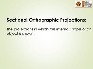
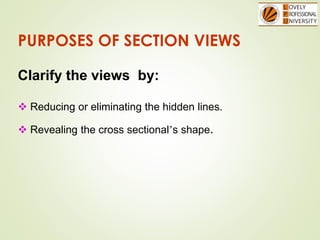
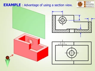
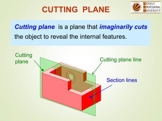
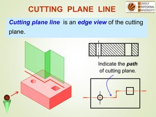
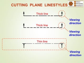
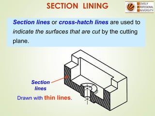
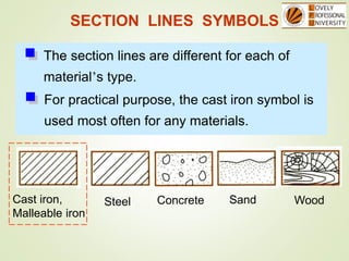
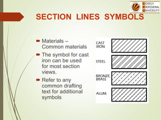
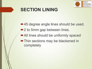
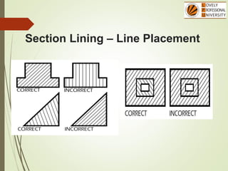
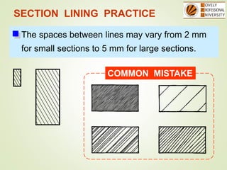
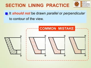
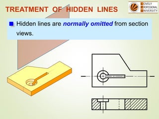
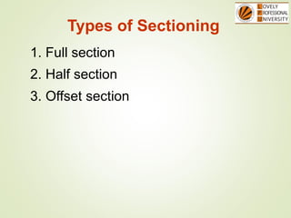
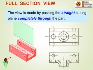
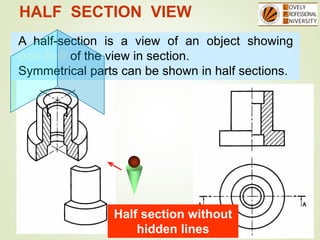
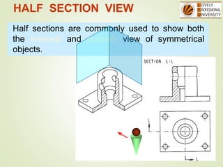
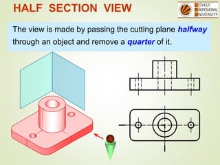
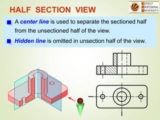
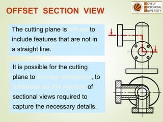
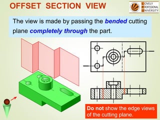
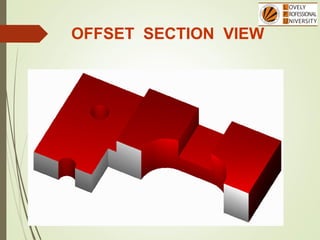
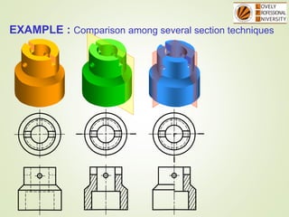
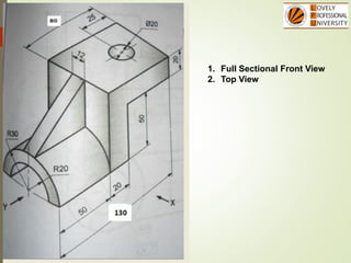
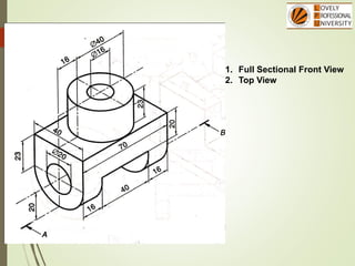
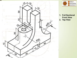
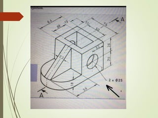
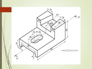
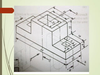
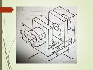
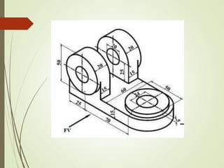
Sectional Views
Unit 4
Sectional Orthographic Projections:
The projections in which the internal shape of an
object is shown.
PURPOSES OF SECTION VIEWS
Clarify the views by:
 Reducing or eliminating the hidden lines.
 Revealing the cross sectional’s shape.
EXAMPLE : Advantage of using a section view.
Cutting
plane
CUTTING PLANE
Cutting plane line
Cutting plane is a plane that imaginarily cuts
the object to reveal the internal features.
Section lines
Cutting plane line is an edge view of the cutting
plane.
CUTTING PLANE LINE
Indicate the path
of cutting plane.
Thick line
Thick line
Thin line
CUTTING PLANE LINESTYLES
Viewing
direction
Viewing
direction
Viewing
direction
SECTION LINING
Section lines or cross-hatch lines are used to
indicate the surfaces that are cut by the cutting
plane.
Section
lines
Drawn with thin lines.
SECTION LINES SYMBOLS
The section lines are different for each of
material’s type.
Cast iron,
Malleable iron
Steel Concrete Sand Wood
For practical purpose, the cast iron symbol is
used most often for any materials.
SECTION LINES SYMBOLS
 Materials –
Common materials
 The symbol for cast
iron can be used
for most section
views.
 Refer to any
common drafting
text for additional
symbols
SECTION LINING
45 degree angle lines should be used.
2 to 5mm gap between lines.
All lines should be uniformly spaced
Thin sections may be blackened in
completely
Section Lining – Line
Placement
 Lines should never be parallel or perpendicular to the
object lines.
 If the outline of the object has 45 degree lines, 30 or 60
degree lines should be used.
 Assemblies with several parts should be lined with
varying angle section lines.
Section Lining – Line Placement
SECTION LINING PRACTICE
The spaces between lines may vary from 2 mm
for small sections to 5 mm for large sections.
COMMON MISTAKE
SECTION LINING PRACTICE
It should not be drawn parallel or perpendicular
to contour of the view.
COMMON MISTAKE
TREATMENT OF HIDDEN LINES
Hidden lines are normally omitted from section
views.
Types of Sectioning
1. Full section
3. Offset section
2. Half section
FULL SECTION VIEW
The view is made by passing the straight cutting
plane completely through the part.
HALF SECTION VIEW
A half-section is a view of an object showing
one-half of the view in section.
Symmetrical parts can be shown in half sections.
Half section without
hidden lines
HALF SECTION VIEW
Half sections are commonly used to show both
the internal and outside view of symmetrical
objects.
HALF SECTION VIEW
The view is made by passing the cutting plane halfway
through an object and remove a quarter of it.
HALF SECTION VIEW
A center line is used to separate the sectioned half
from the unsectioned half of the view.
Hidden line is omitted in unsection half of the view.
OFFSET SECTION VIEW
The cutting plane is off-set to
include features that are not in
a straight line.
It is possible for the cutting
plane to change directions, to
minimise on the number of
sectional views required to
capture the necessary details.
OFFSET SECTION VIEW
The view is made by passing the bended cutting
plane completely through the part.
Do not show the edge views
of the cutting plane.
OFFSET SECTION VIEW
EXAMPLE : Comparison among several section techniques
1. Full Sectional Front View
2. Top View
1. Full Sectional Front View
2. Top View
1. Full Sectional
Front View
2. Top View
Thank You

Sectioning Theory upload engineeering physics

  • 1.
  • 2.
    Sectional Orthographic Projections: Theprojections in which the internal shape of an object is shown.
  • 3.
    PURPOSES OF SECTIONVIEWS Clarify the views by:  Reducing or eliminating the hidden lines.  Revealing the cross sectional’s shape.
  • 4.
    EXAMPLE : Advantageof using a section view.
  • 5.
    Cutting plane CUTTING PLANE Cutting planeline Cutting plane is a plane that imaginarily cuts the object to reveal the internal features. Section lines
  • 6.
    Cutting plane lineis an edge view of the cutting plane. CUTTING PLANE LINE Indicate the path of cutting plane.
  • 7.
    Thick line Thick line Thinline CUTTING PLANE LINESTYLES Viewing direction Viewing direction Viewing direction
  • 8.
    SECTION LINING Section linesor cross-hatch lines are used to indicate the surfaces that are cut by the cutting plane. Section lines Drawn with thin lines.
  • 9.
    SECTION LINES SYMBOLS Thesection lines are different for each of material’s type. Cast iron, Malleable iron Steel Concrete Sand Wood For practical purpose, the cast iron symbol is used most often for any materials.
  • 10.
    SECTION LINES SYMBOLS Materials – Common materials  The symbol for cast iron can be used for most section views.  Refer to any common drafting text for additional symbols
  • 11.
    SECTION LINING 45 degreeangle lines should be used. 2 to 5mm gap between lines. All lines should be uniformly spaced Thin sections may be blackened in completely
  • 12.
    Section Lining –Line Placement  Lines should never be parallel or perpendicular to the object lines.  If the outline of the object has 45 degree lines, 30 or 60 degree lines should be used.  Assemblies with several parts should be lined with varying angle section lines.
  • 13.
    Section Lining –Line Placement
  • 14.
    SECTION LINING PRACTICE Thespaces between lines may vary from 2 mm for small sections to 5 mm for large sections. COMMON MISTAKE
  • 15.
    SECTION LINING PRACTICE Itshould not be drawn parallel or perpendicular to contour of the view. COMMON MISTAKE
  • 16.
    TREATMENT OF HIDDENLINES Hidden lines are normally omitted from section views.
  • 17.
    Types of Sectioning 1.Full section 3. Offset section 2. Half section
  • 18.
    FULL SECTION VIEW Theview is made by passing the straight cutting plane completely through the part.
  • 19.
    HALF SECTION VIEW Ahalf-section is a view of an object showing one-half of the view in section. Symmetrical parts can be shown in half sections. Half section without hidden lines
  • 20.
    HALF SECTION VIEW Halfsections are commonly used to show both the internal and outside view of symmetrical objects.
  • 21.
    HALF SECTION VIEW Theview is made by passing the cutting plane halfway through an object and remove a quarter of it.
  • 22.
    HALF SECTION VIEW Acenter line is used to separate the sectioned half from the unsectioned half of the view. Hidden line is omitted in unsection half of the view.
  • 23.
    OFFSET SECTION VIEW Thecutting plane is off-set to include features that are not in a straight line. It is possible for the cutting plane to change directions, to minimise on the number of sectional views required to capture the necessary details.
  • 24.
    OFFSET SECTION VIEW Theview is made by passing the bended cutting plane completely through the part. Do not show the edge views of the cutting plane.
  • 25.
  • 26.
    EXAMPLE : Comparisonamong several section techniques
  • 28.
    1. Full SectionalFront View 2. Top View
  • 29.
    1. Full SectionalFront View 2. Top View
  • 30.
    1. Full Sectional FrontView 2. Top View
  • 36.