ADAMA SCIENCE ANDTECHNOLOGY UNIVERSITY
SCHOOL OF MECHANICAL, CHEMICAL AND MATERIAL
ENGINEERING
DEPARTMENT OF MECHANICAL ENGINEERING
ENGINEERING DRAWING ; MEng1102
CHAPTER-6
SECTIONAL VIEWS
Date, Jun 2024
05/07/25
2.
Learning Outcomes
At theend of the lesson the students will be
able to:
•Define Sections and Identify the Necessity of
sectional views
•List the types of sectioning and differentiate
between them
•Practice the convention in sectioning
•Make practical exercise on both sectional view and
pictorial section.
3.
6.1. Introduction
Sectionsare used to clarify the interior construction
of a part that can not be clearly described by hidden
lines in exterior views.
By taking an imaginary cut through the object and
removing a portion, the inside features may be seen
more clearly.
4.
6.2.Necessity of sectionalviews
To see clearly interior features of the object.
To clarify the interior details of an object that can
not be clearly described by hidden lines.
To reduce confusion.
5.
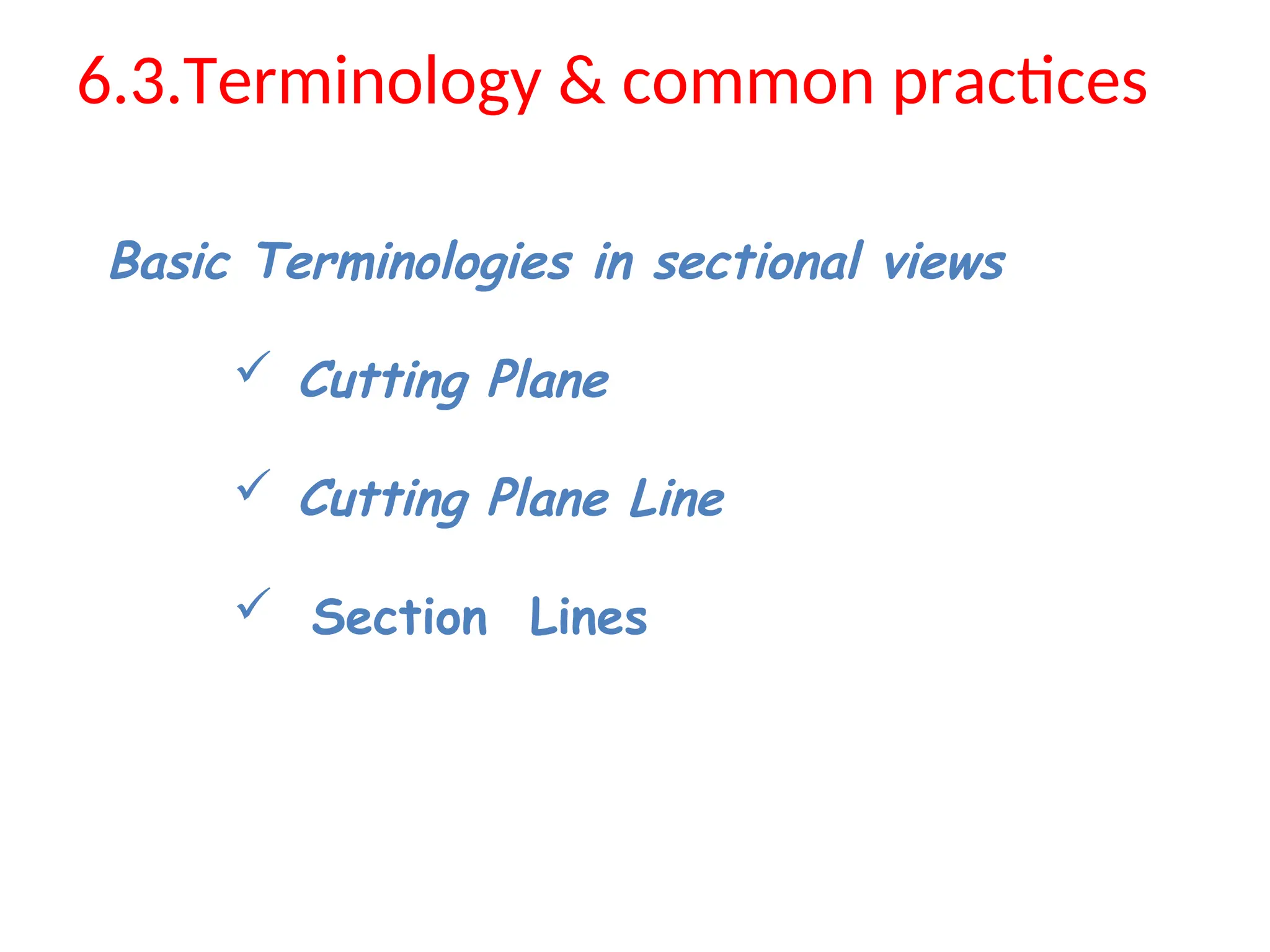
6.3.Terminology & commonpractices
Basic Terminologies in sectional views
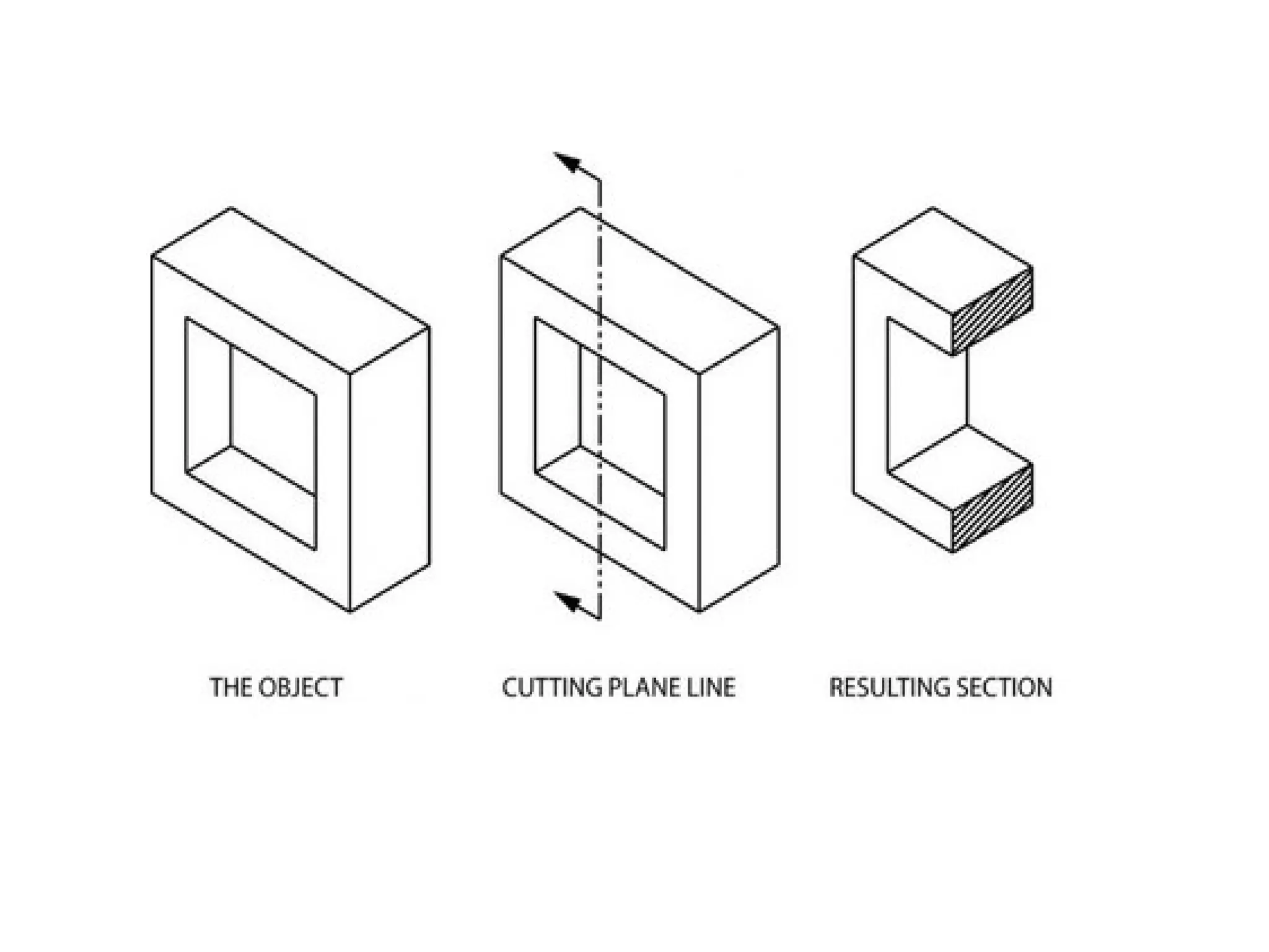
Cutting Plane
Cutting Plane Line
Section Lines
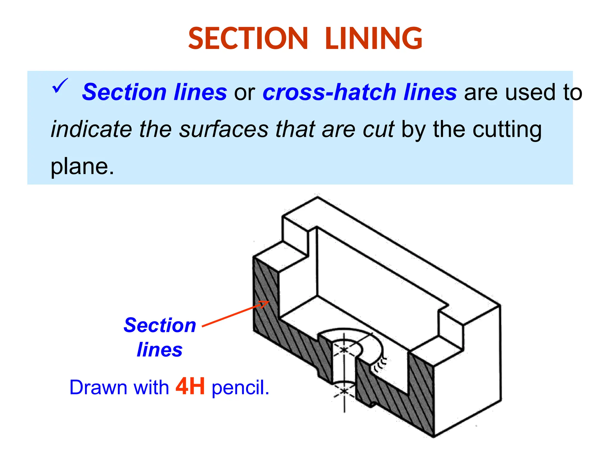
SECTION LINING
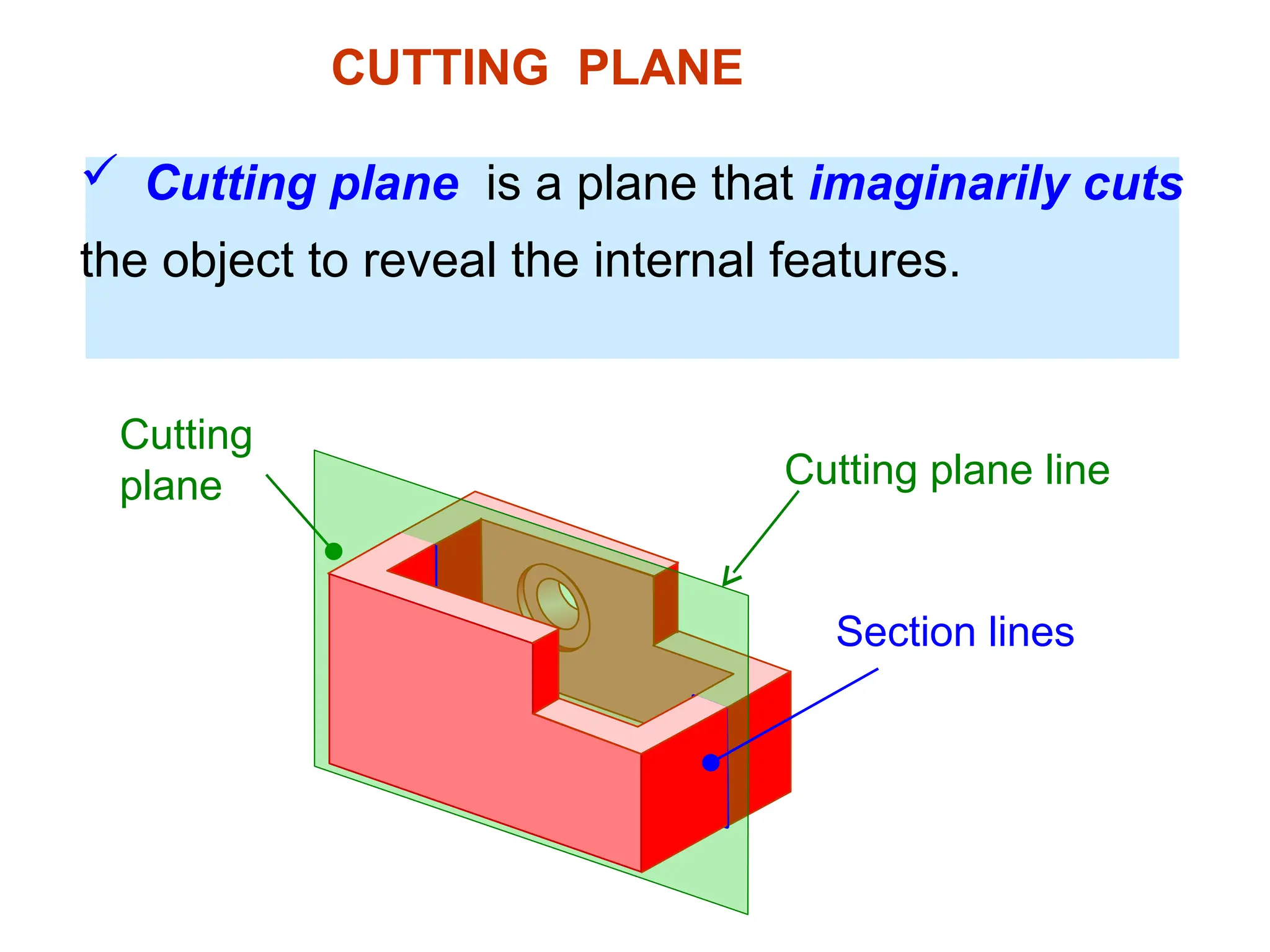
Sectionlines or cross-hatch lines are used to
indicate the surfaces that are cut by the cutting
plane.
Section
lines
Drawn with 4H pencil.
11.
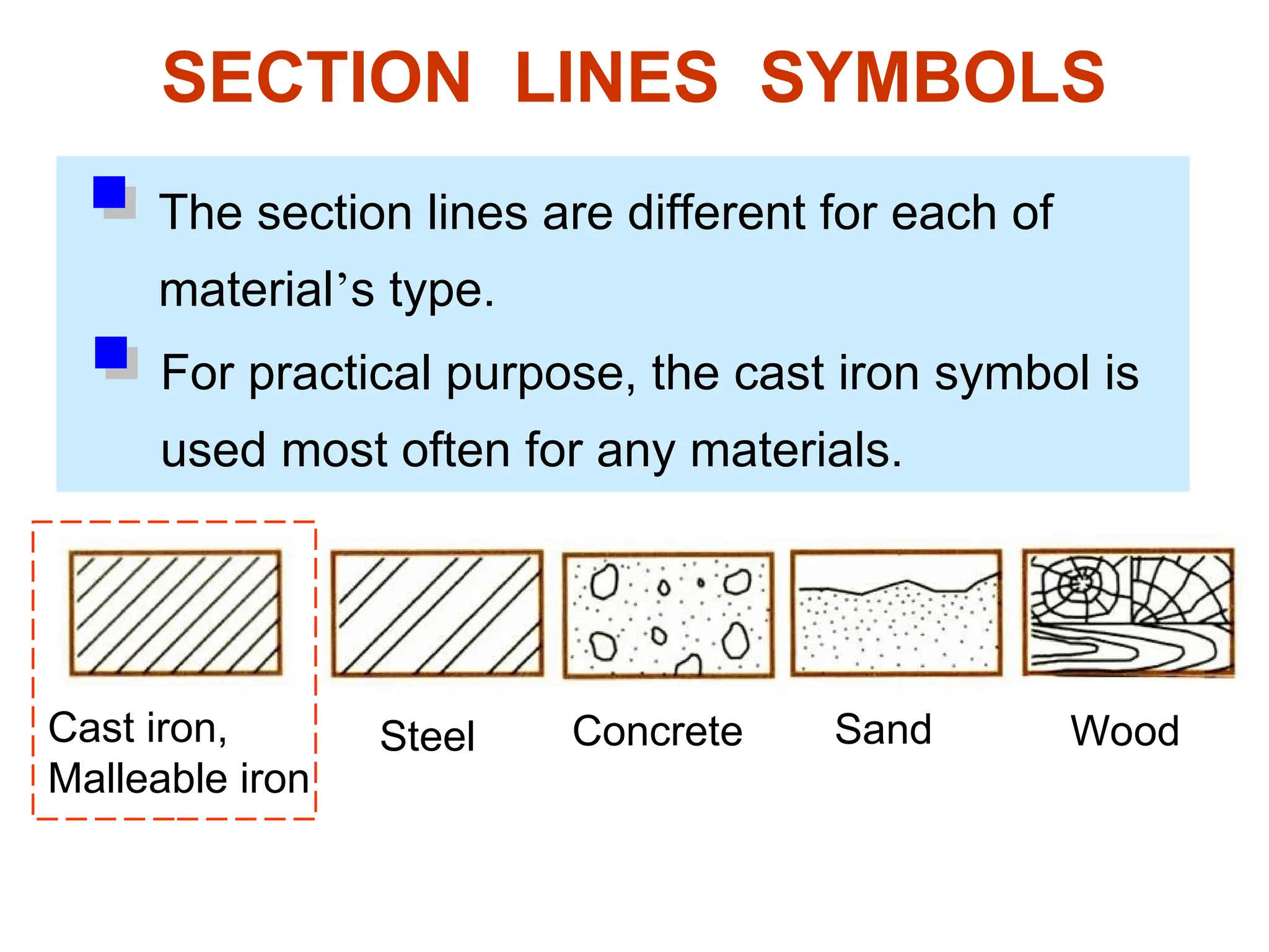
SECTION LINES SYMBOLS
Thesection lines are different for each of
material’s type.
Cast iron,
Malleable iron
Steel Concrete Sand Wood
For practical purpose, the cast iron symbol is
used most often for any materials.
12.
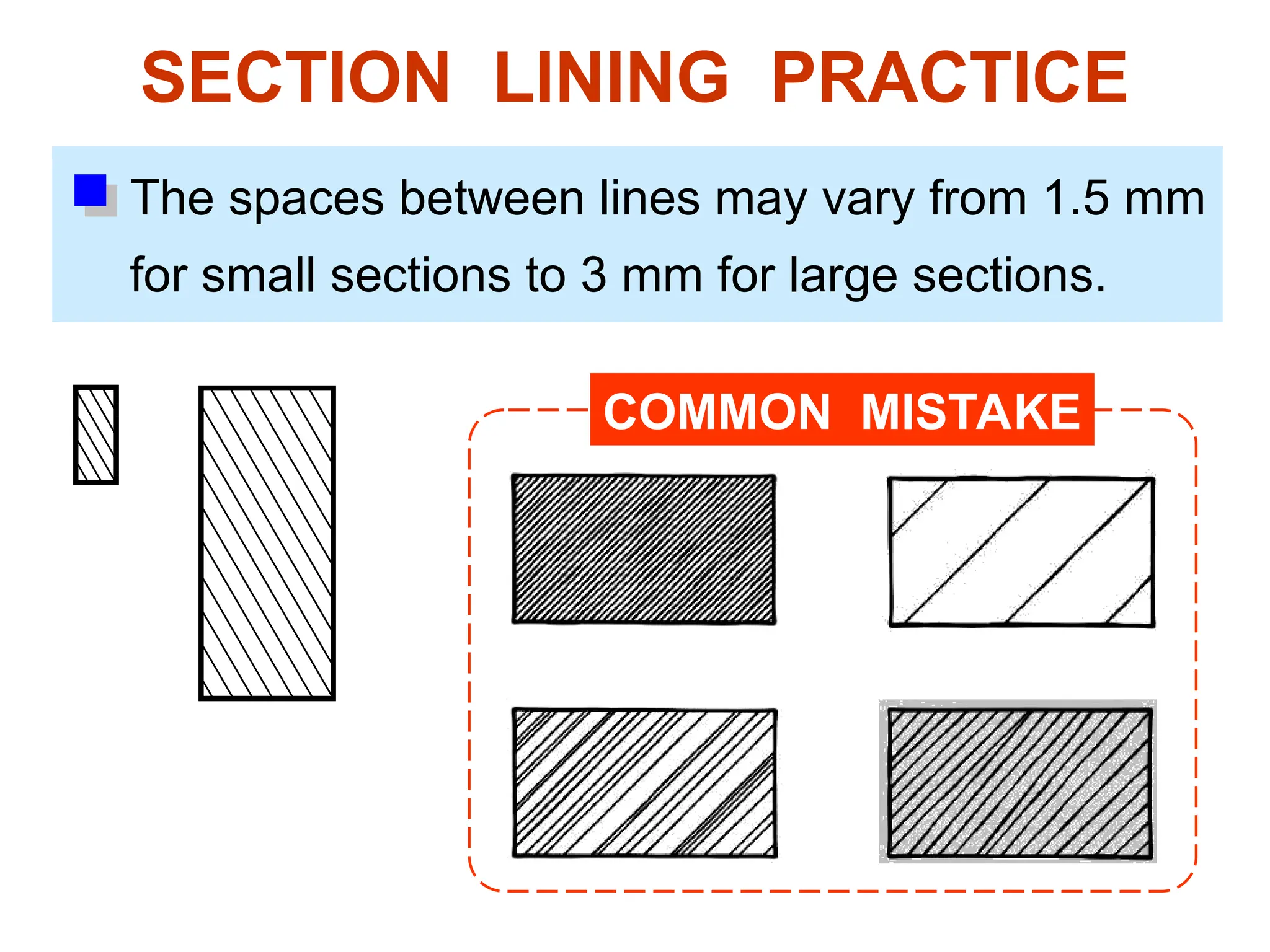
SECTION LINING PRACTICE
Thespaces between lines may vary from 1.5 mm
for small sections to 3 mm for large sections.
COMMON MISTAKE
13.
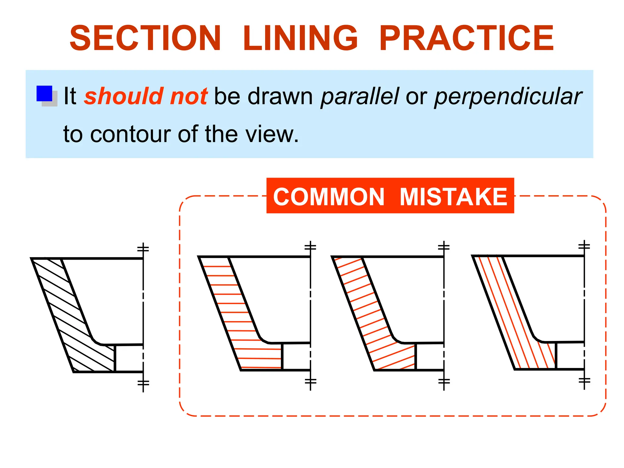
SECTION LINING PRACTICE
Itshould not be drawn parallel or perpendicular
to contour of the view.
COMMON MISTAKE
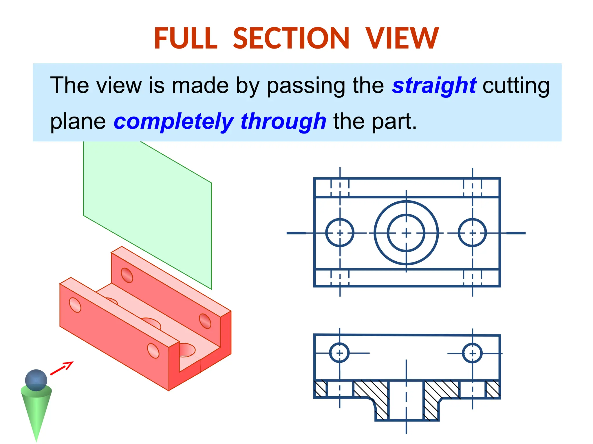
FULL SECTION VIEW
Theview is made by passing the straight cutting
plane completely through the part.
16.
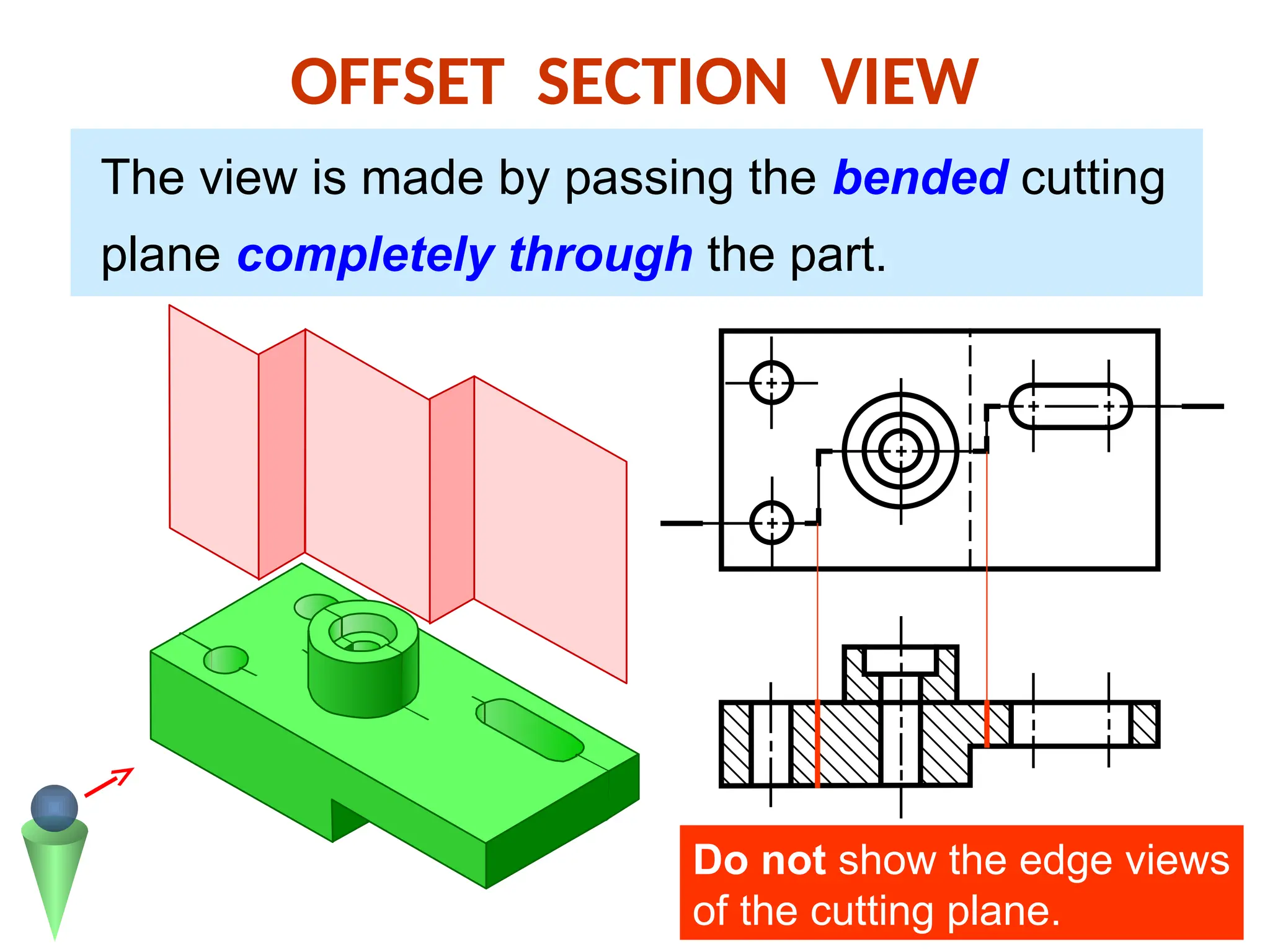
OFFSET SECTION VIEW
Theview is made by passing the bended cutting
plane completely through the part.
Do not show the edge views
of the cutting plane.
17.
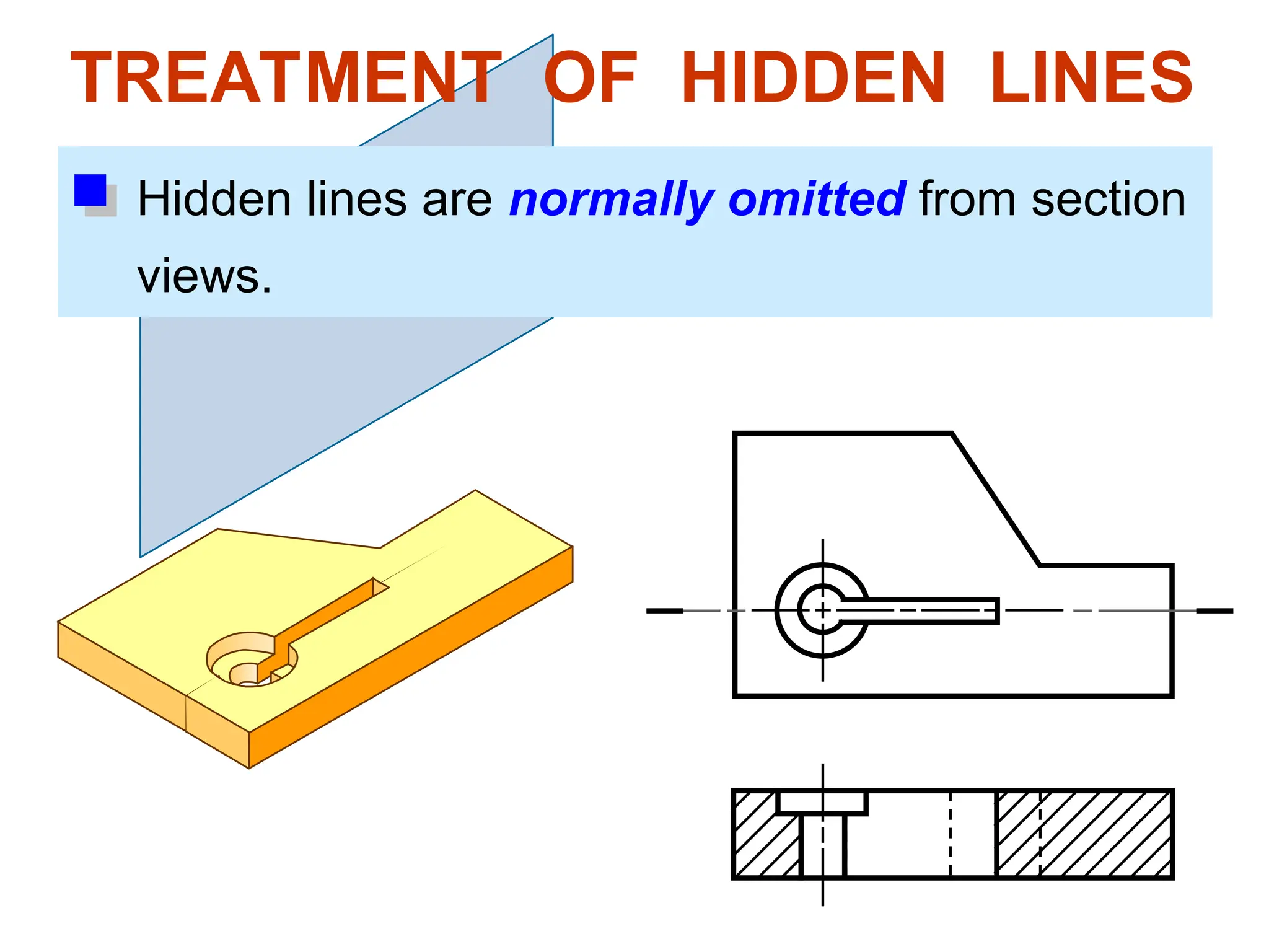
TREATMENT OF HIDDENLINES
Hidden lines are normally omitted from section
views.
18.
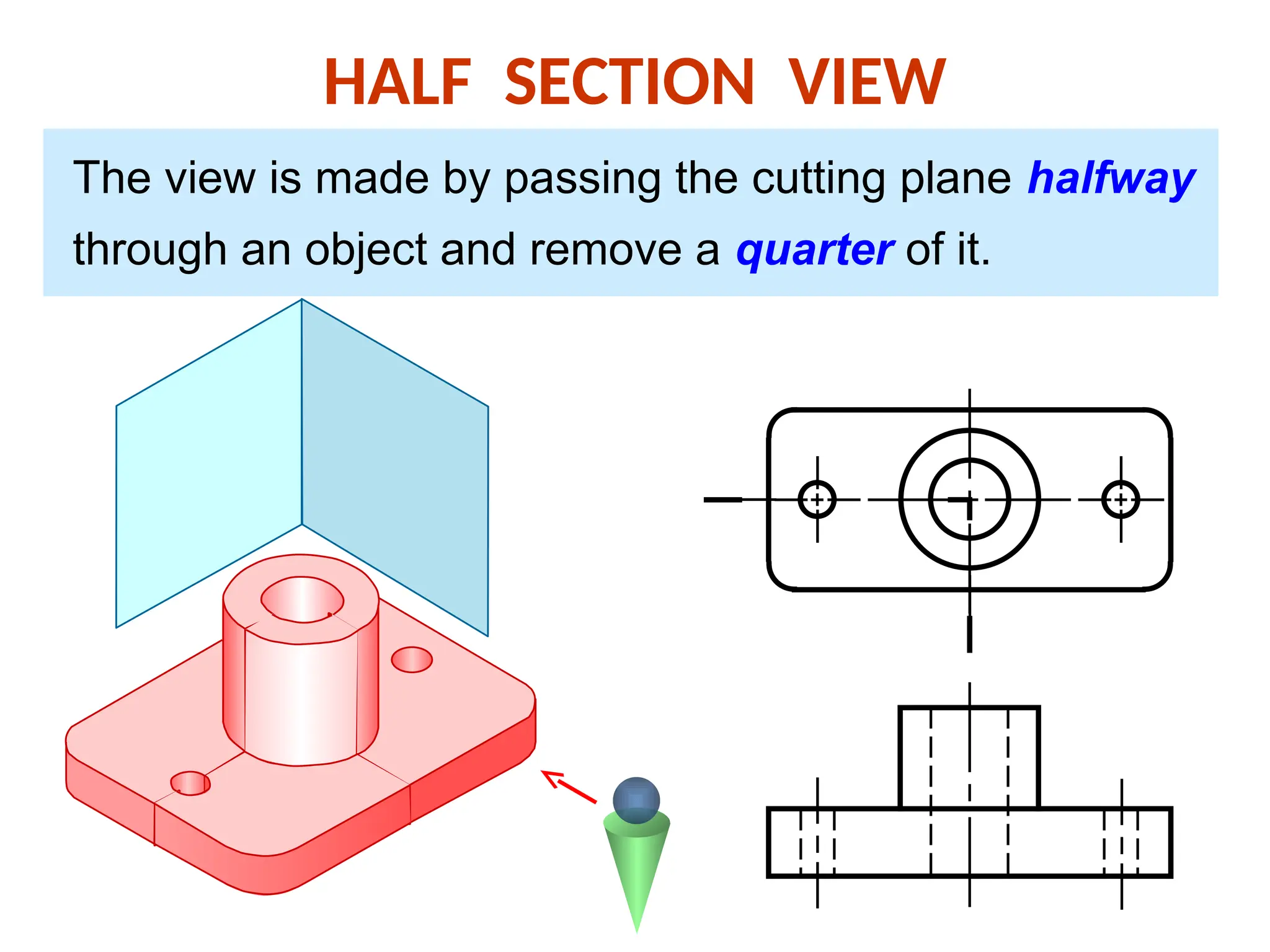
HALF SECTION VIEW
Theview is made by passing the cutting plane halfway
through an object and remove a quarter of it.
19.
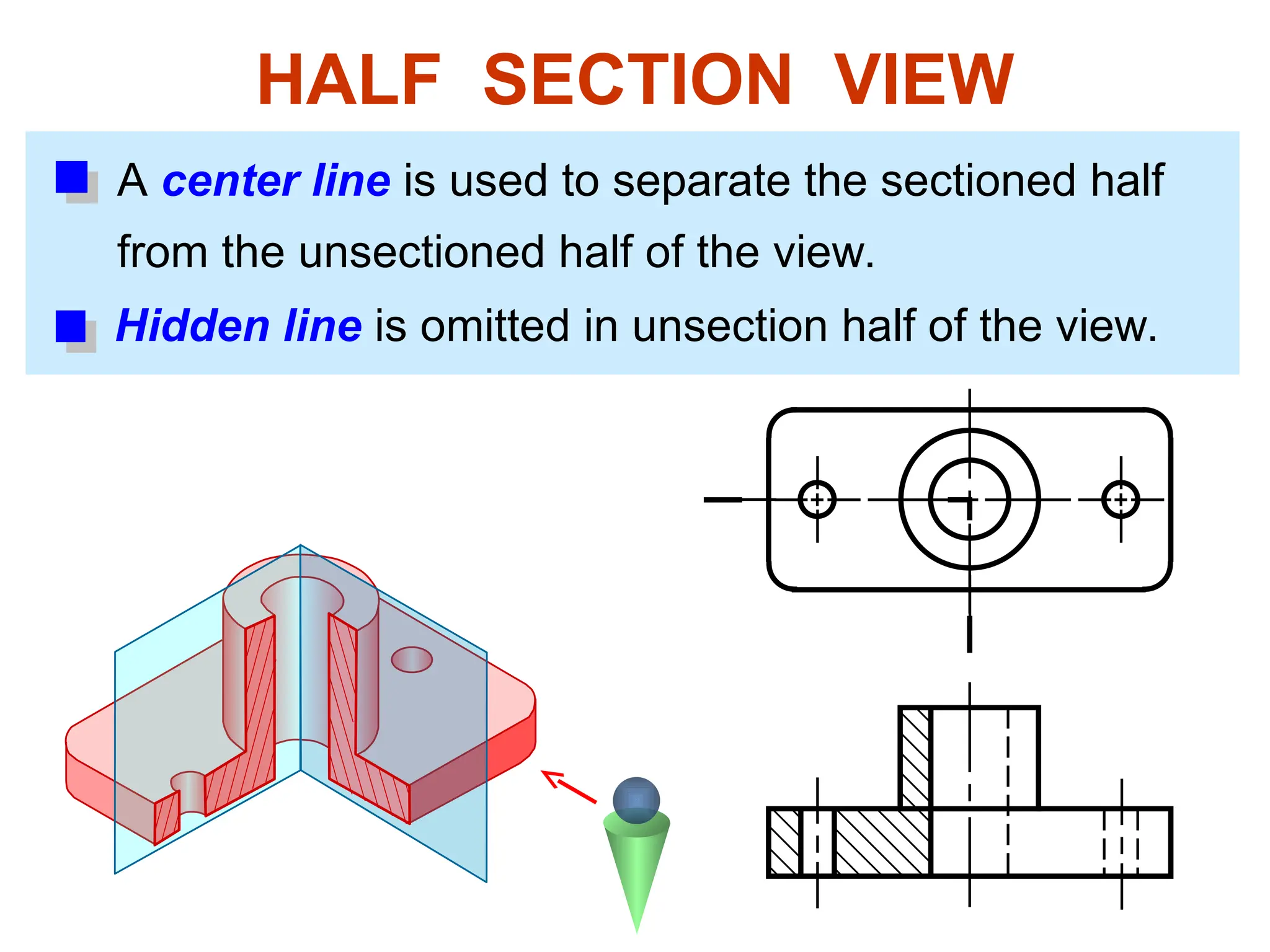
HALF SECTION VIEW
Acenter line is used to separate the sectioned half
from the unsectioned half of the view.
Hidden line is omitted in unsection half of the view.
20.
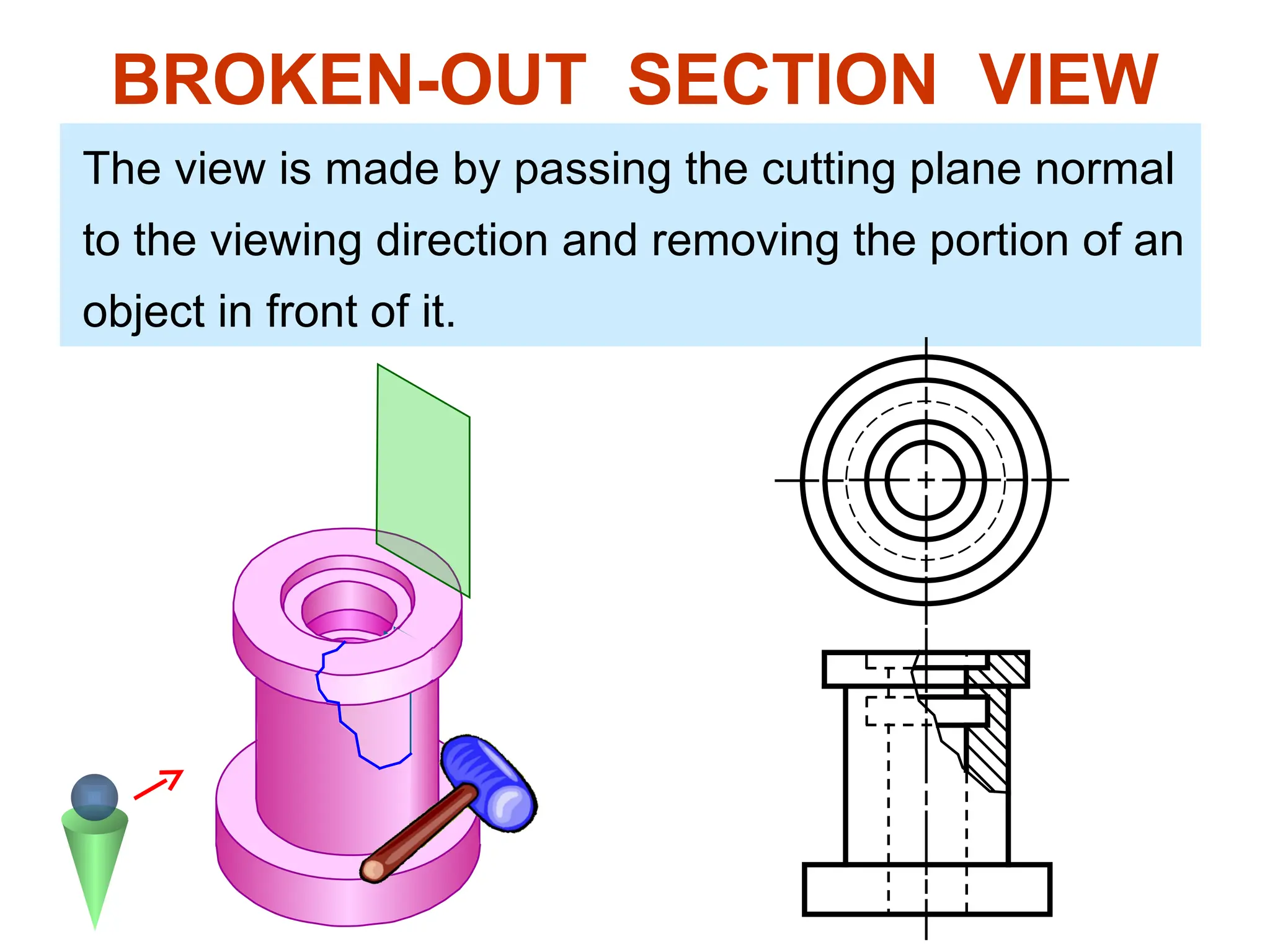
The view ismade by passing the cutting plane normal
to the viewing direction and removing the portion of an
object in front of it.
BROKEN-OUT SECTION VIEW
21.
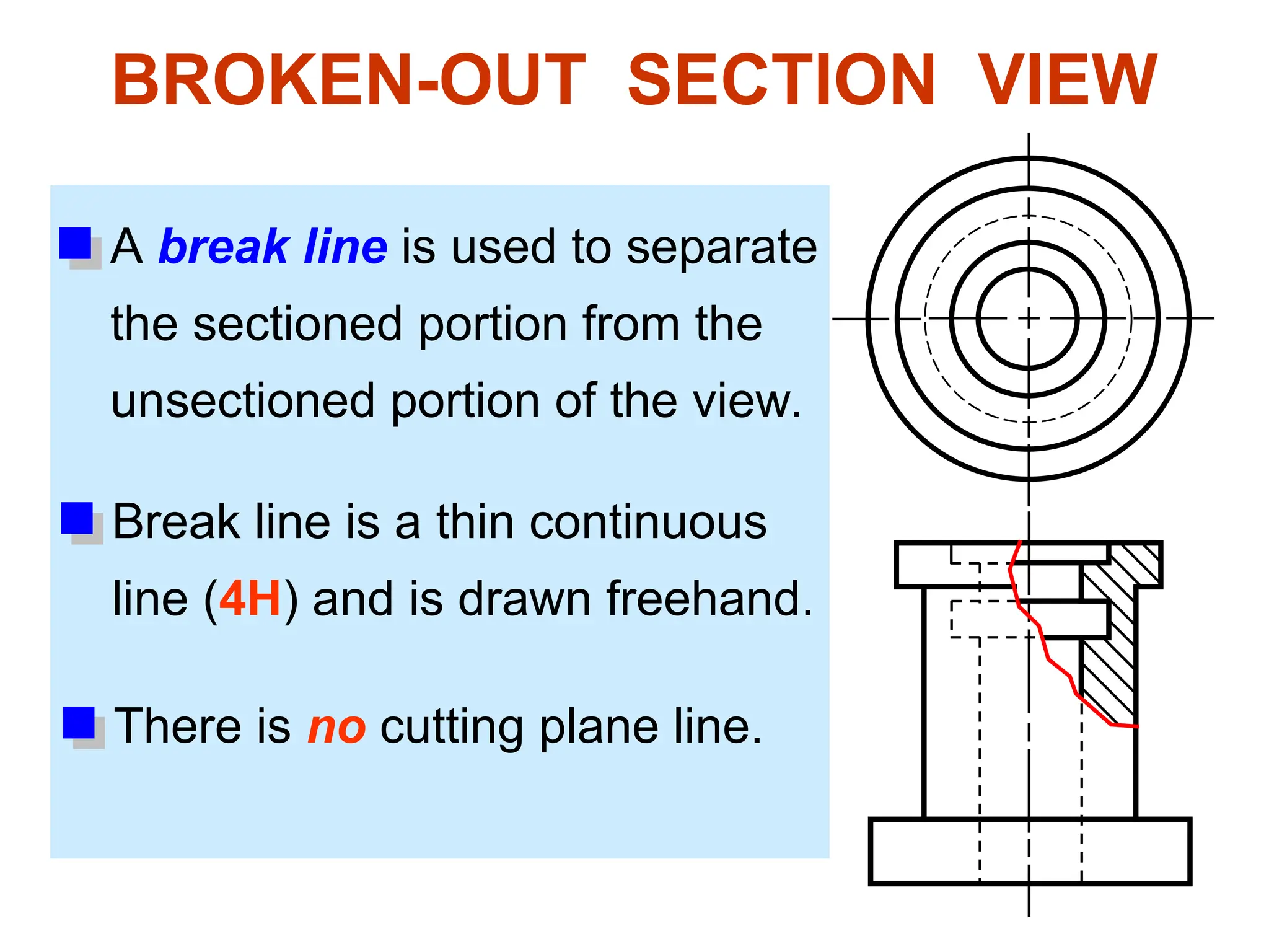
A break lineis used to separate
the sectioned portion from the
unsectioned portion of the view.
BROKEN-OUT SECTION VIEW
There is no cutting plane line.
Break line is a thin continuous
line (4H) and is drawn freehand.
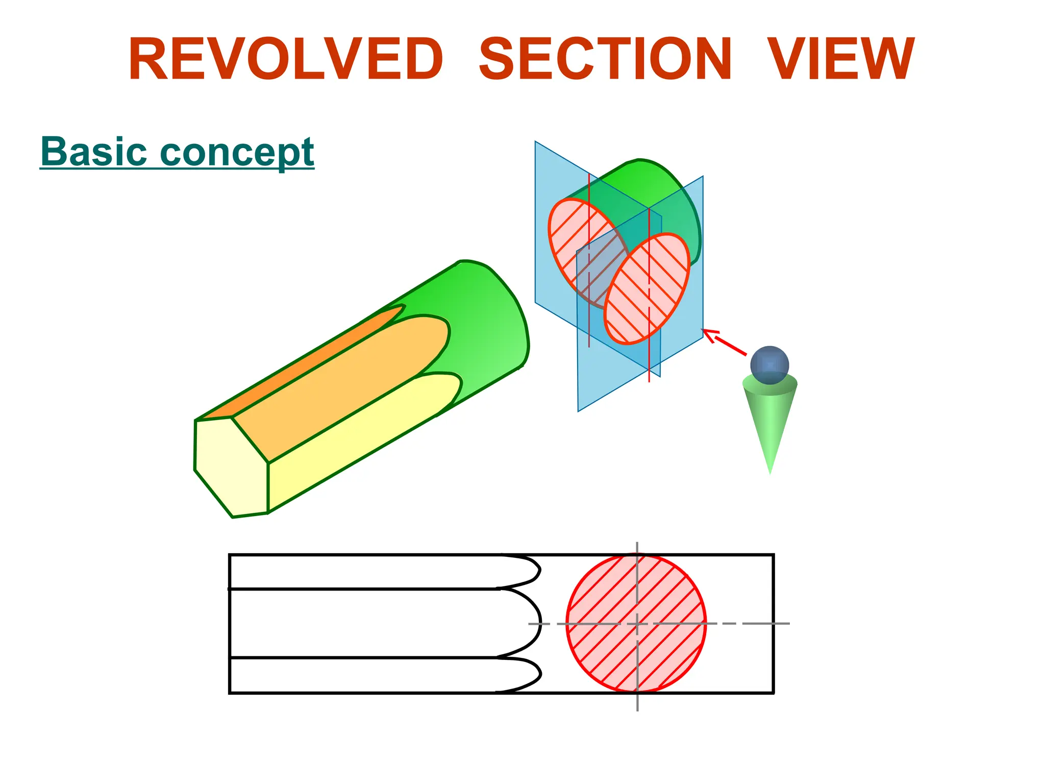
Revolved sections showcross-sectional
features of a part.
No need for additional orthographic views.
This section is especially helpful when a
cross-section varies.
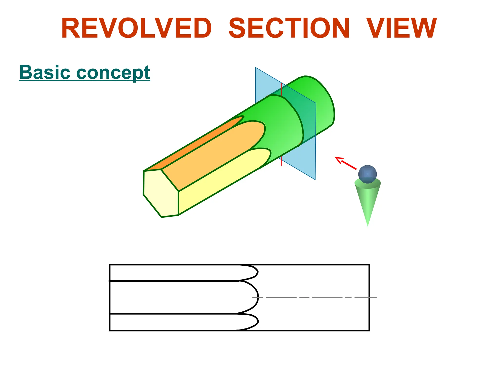
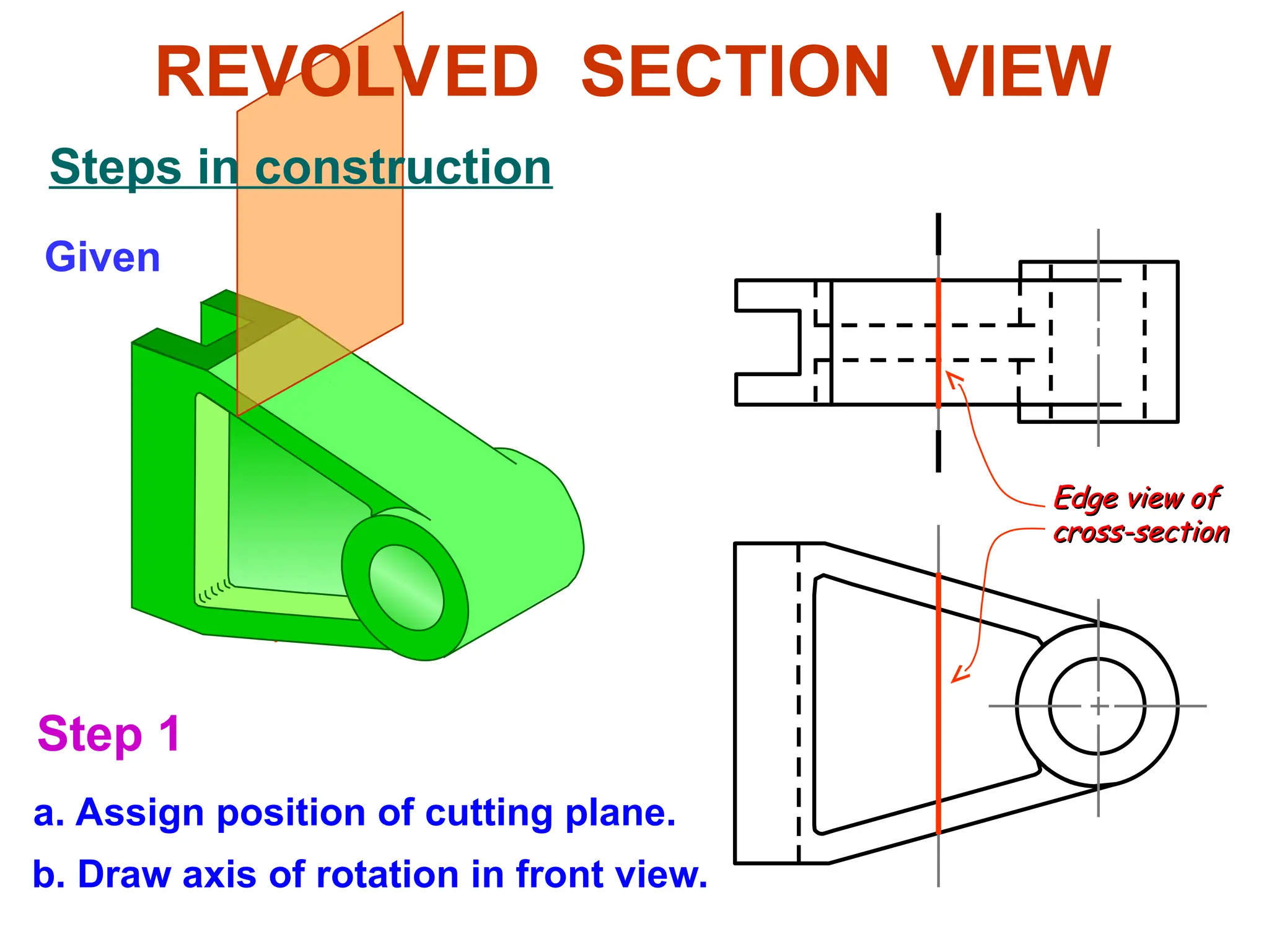
REVOLVED SECTION VIEW
Given
Step 1
a. Assignposition of cutting plane.
b. Draw axis of rotation in front view.
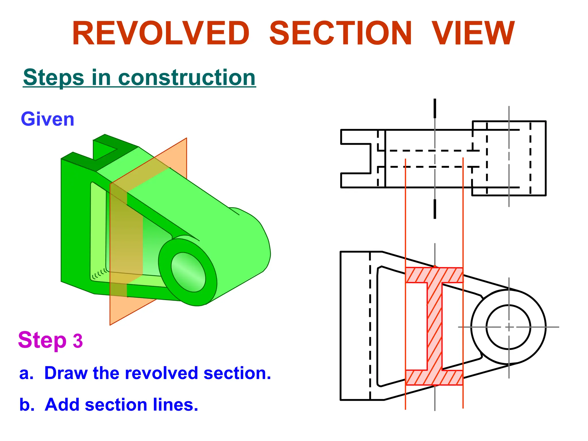
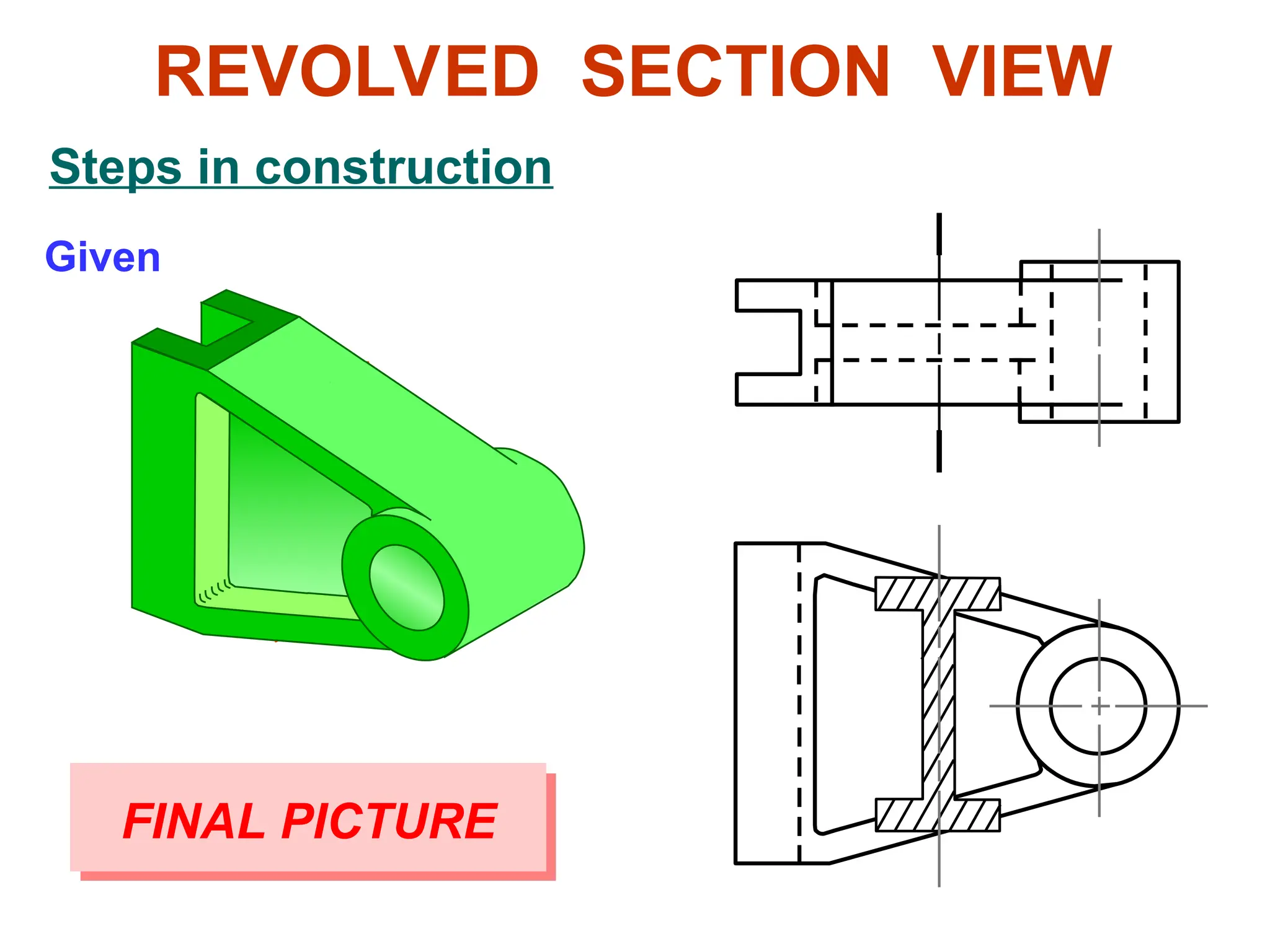
Steps in construction
REVOLVED SECTION VIEW
Edge view of
Edge view of
cross-section
cross-section
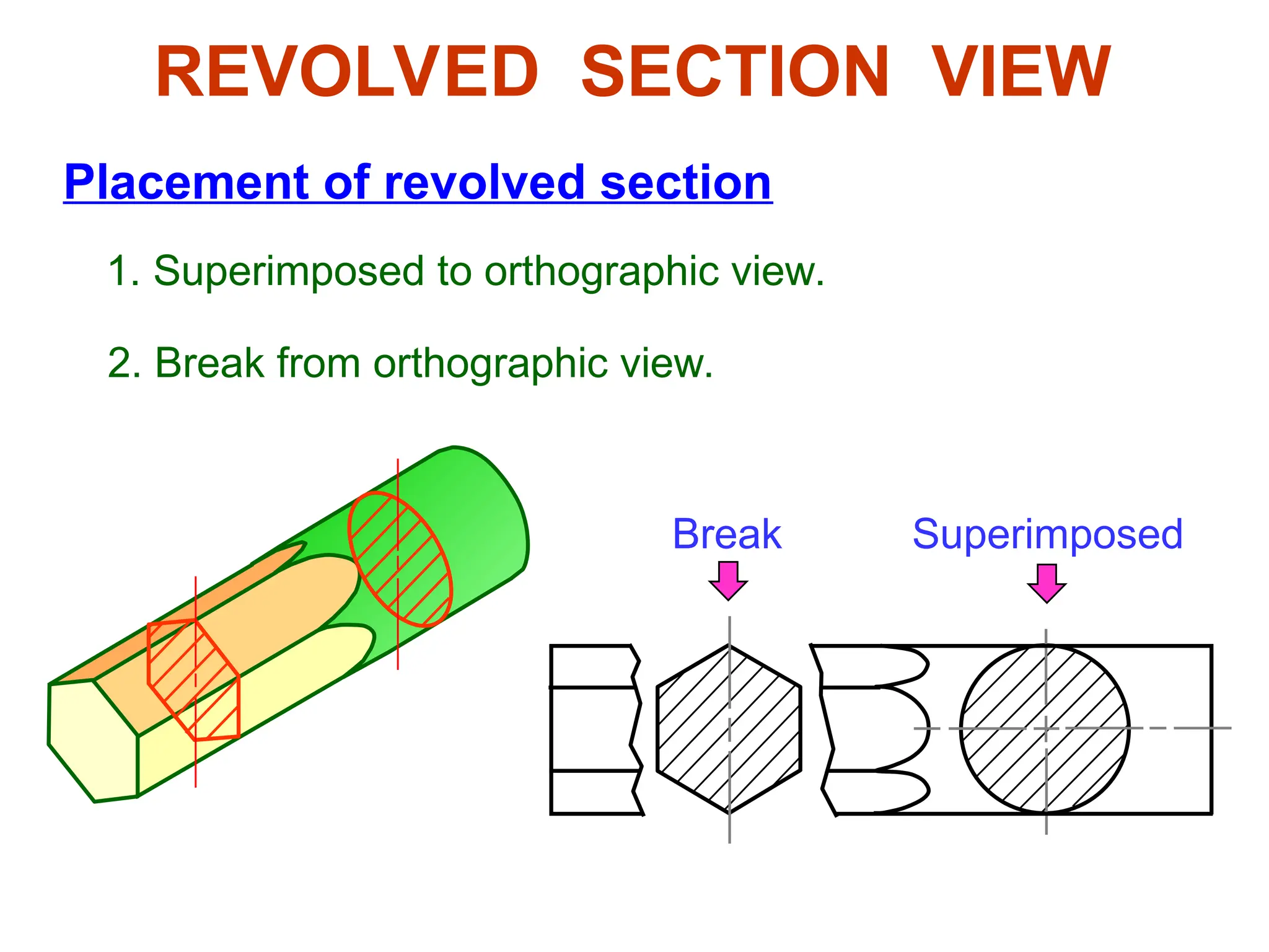
Placement of revolvedsection
1. Superimposed to orthographic view.
Superimposed
Break
2. Break from orthographic view.
REVOLVED SECTION VIEW
31.
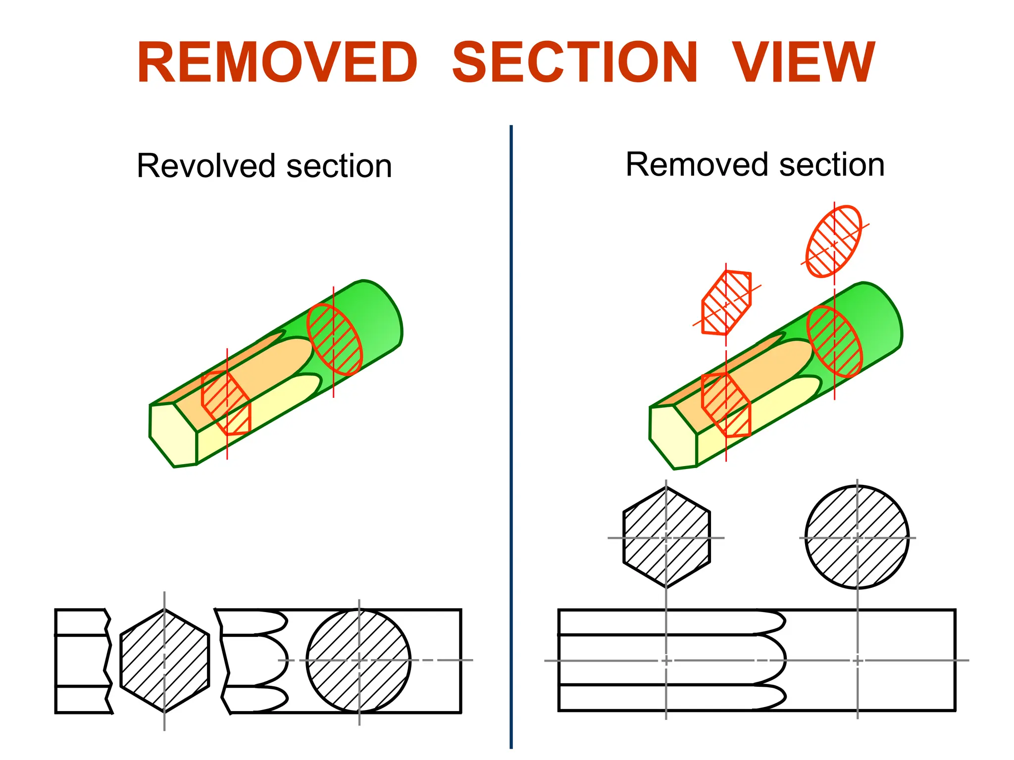
6. Removed section
Removedsection is revolved section.
Used where space does not enough for
revolved section
Can be located elsewhere on a drawing
with properly labeled
REMOVED SECTION VIEW
Section view is shown outside the view.
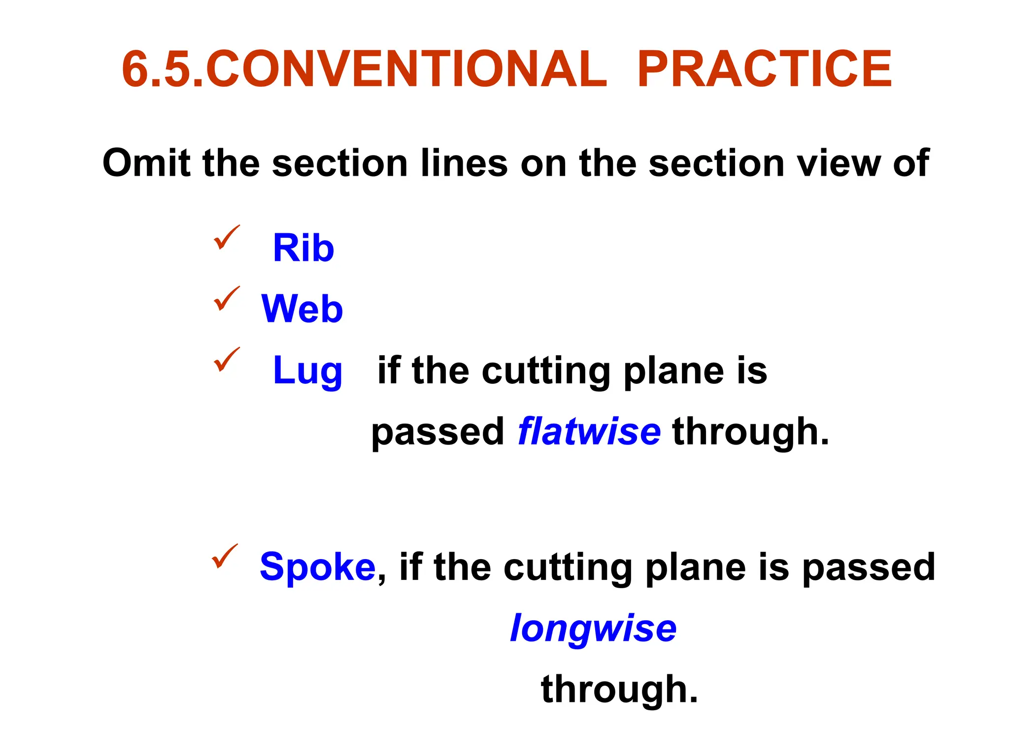
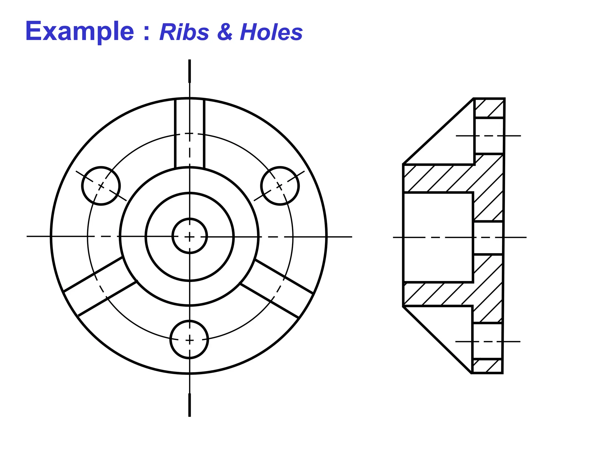
6.5.CONVENTIONAL PRACTICE
Omit thesection lines on the section view of
Rib
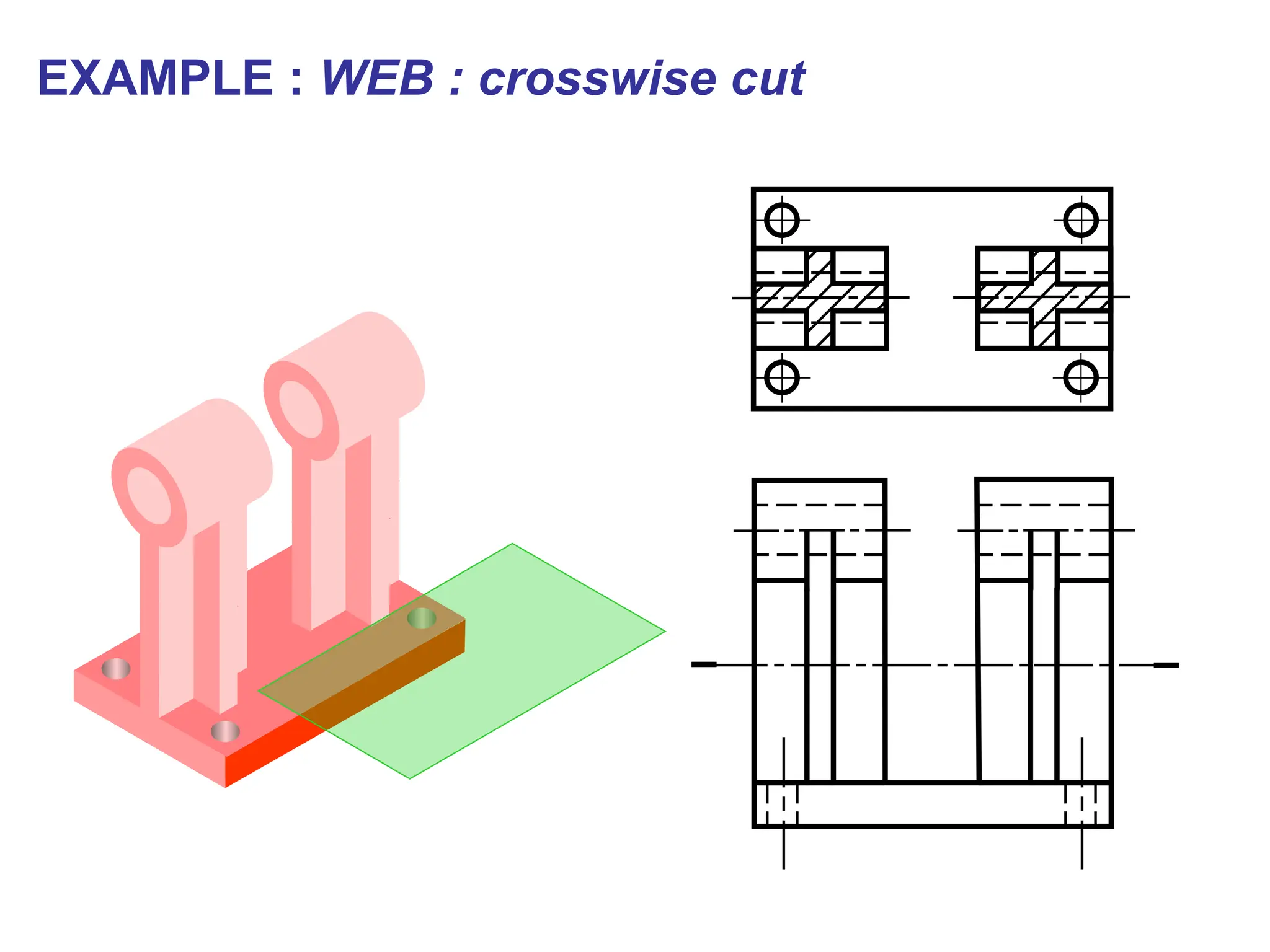
Web
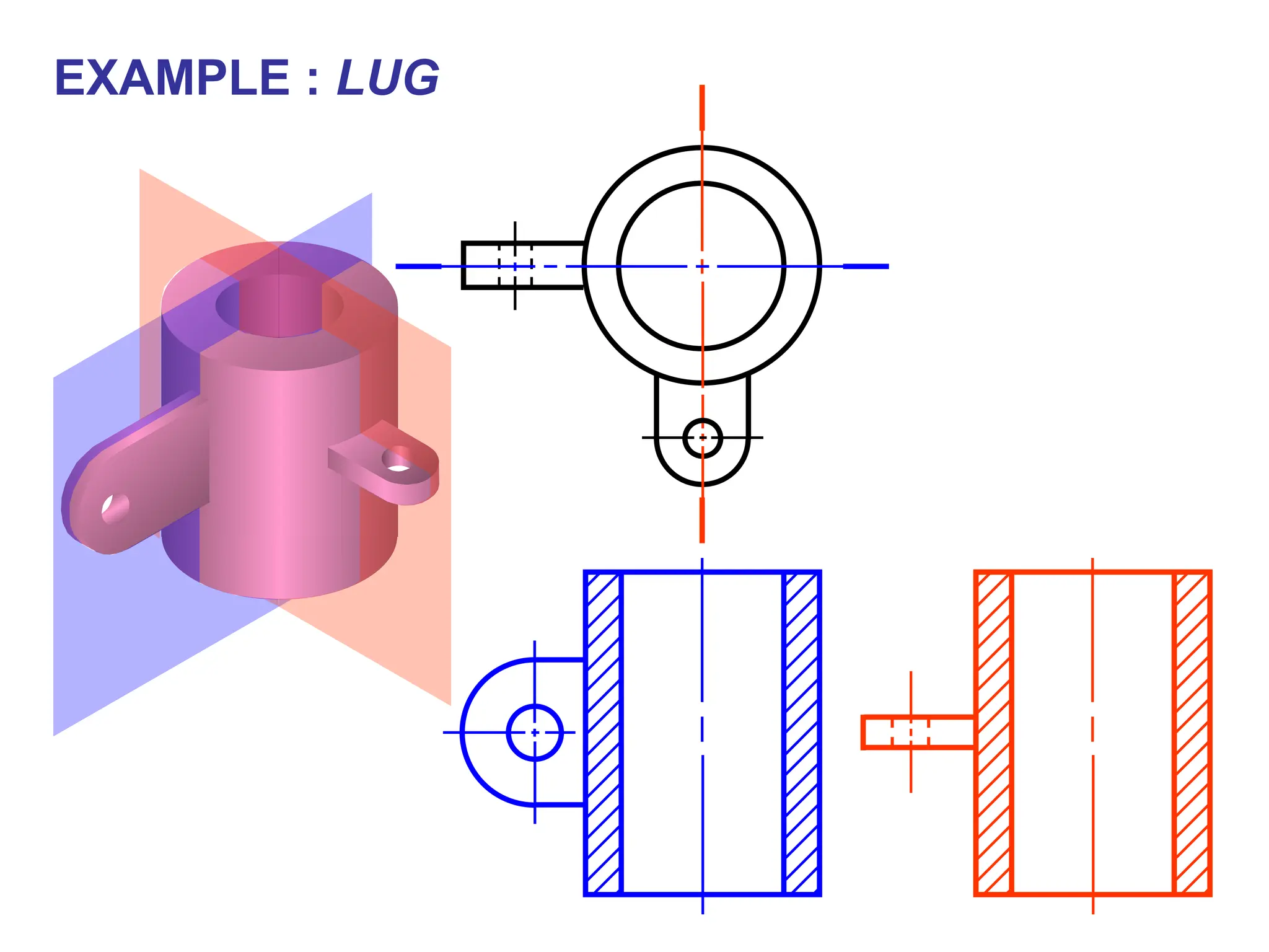
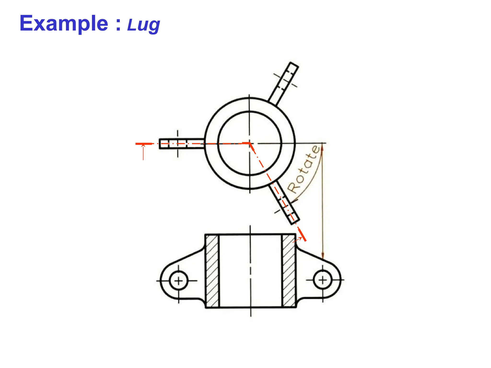
Lug if the cutting plane is
passed flatwise through.
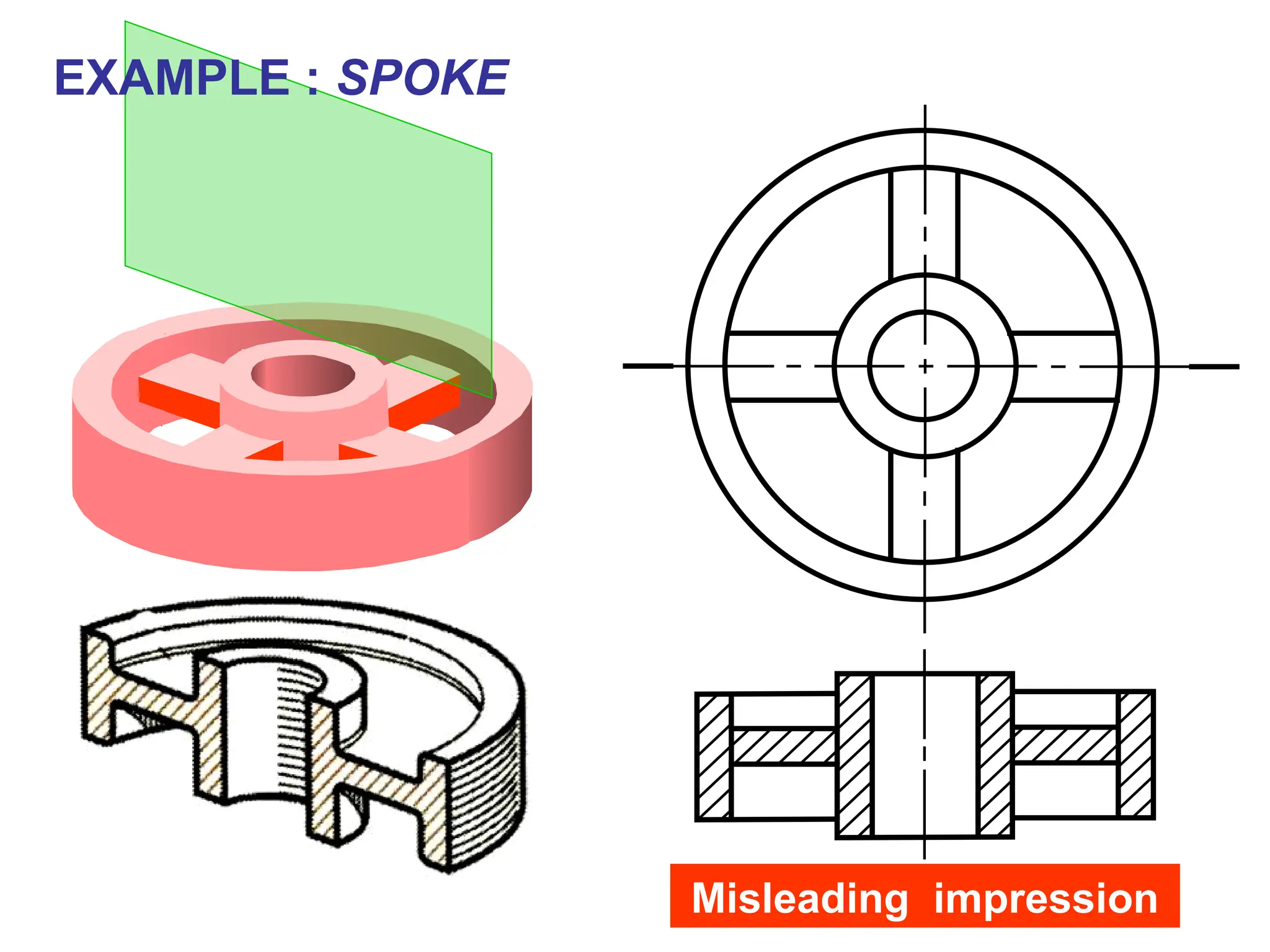
Spoke, if the cutting plane is passed
longwise
through.
34.
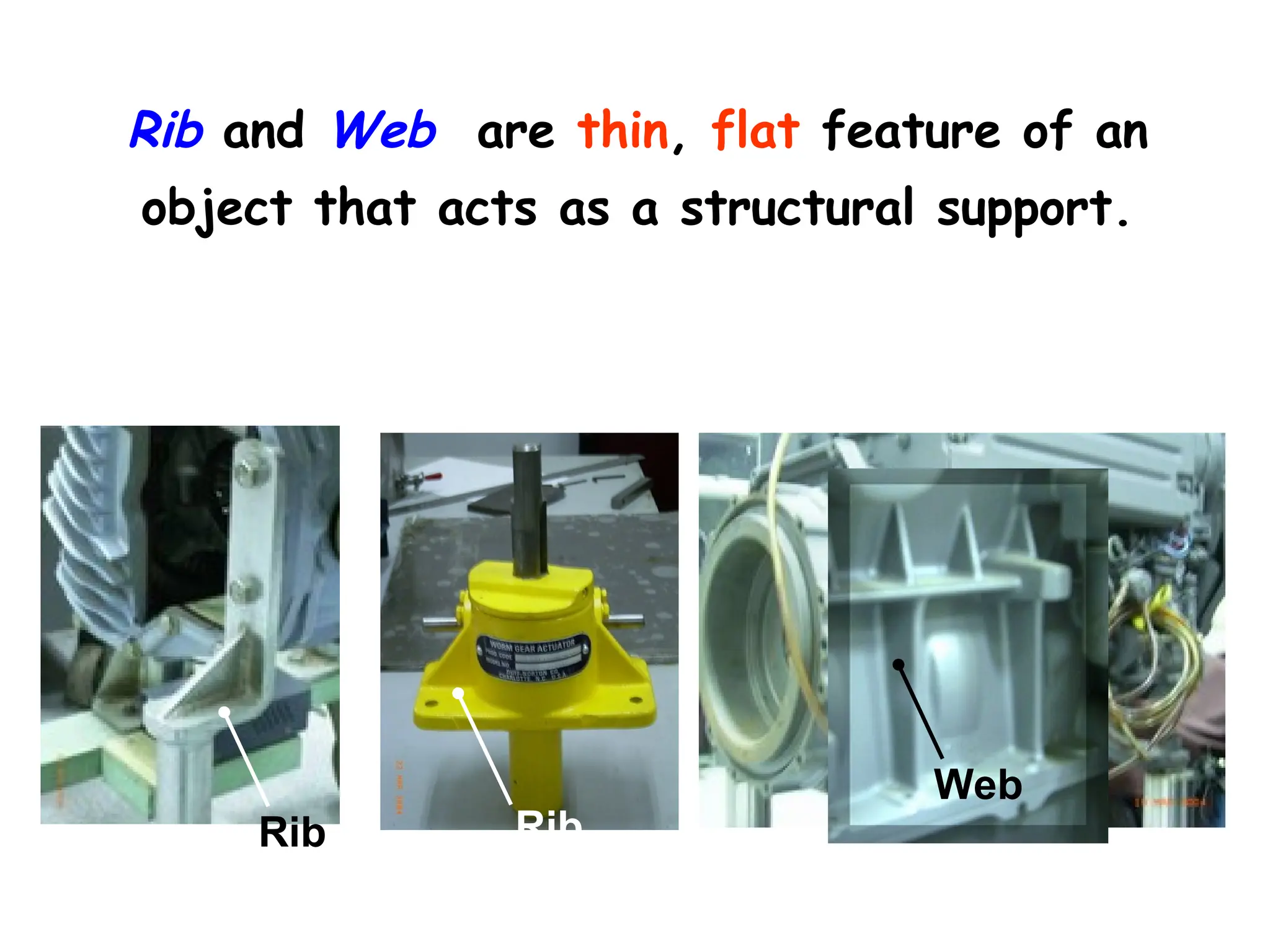
Rib and Webare thin, flat feature of an
object that acts as a structural support.
Rib Rib
Web
35.
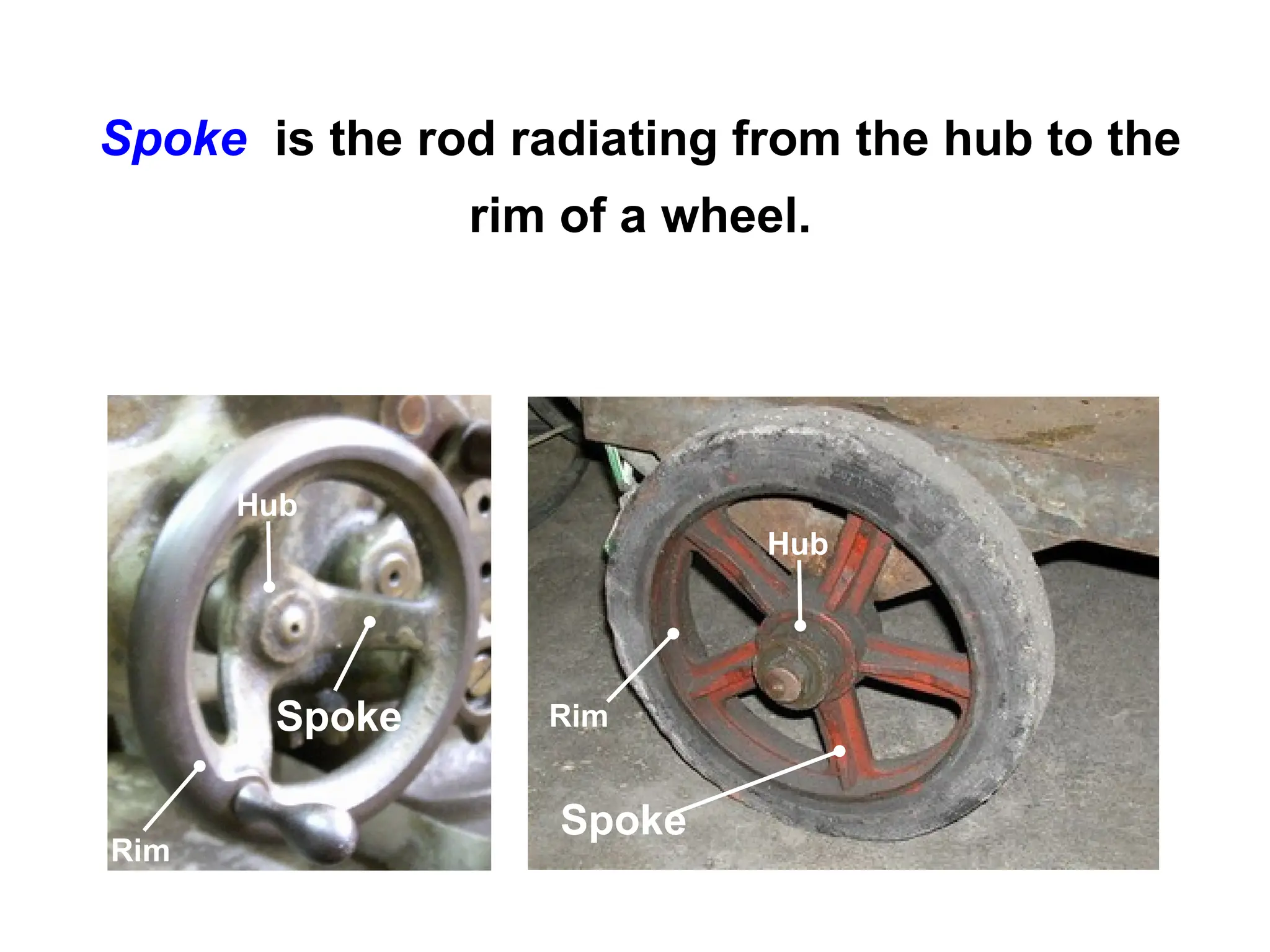
Rim
Spoke is therod radiating from the hub to the
rim of a wheel.
Spoke
Spoke
Rim
Hub
Hub
36.
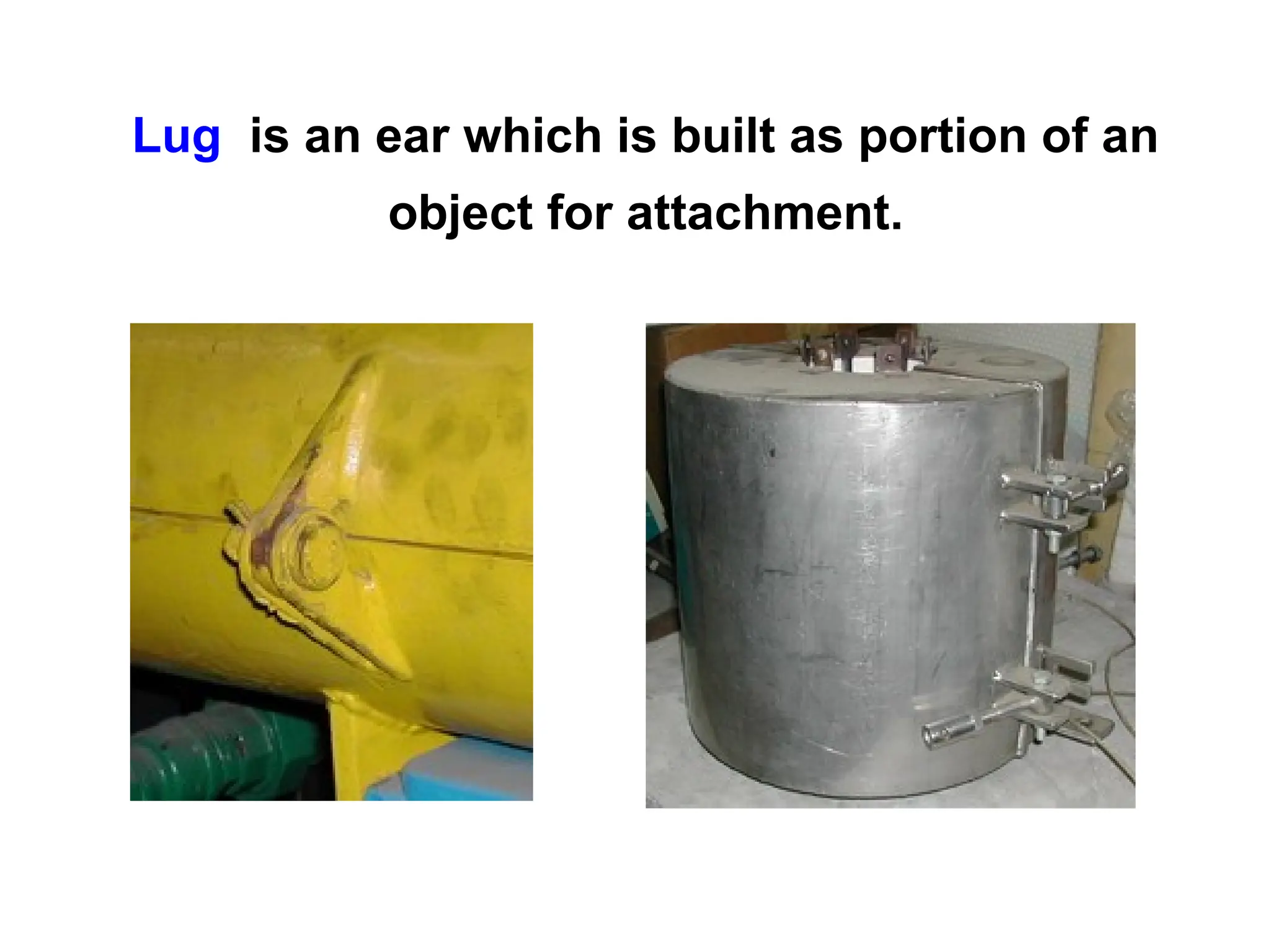
Lug is anear which is built as portion of an
object for attachment.
37.
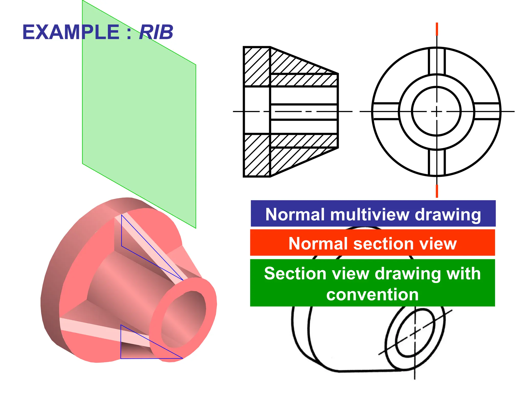
EXAMPLE : RIB
Normalmultiview drawing
Normal section view
Section view drawing with
convention
38.
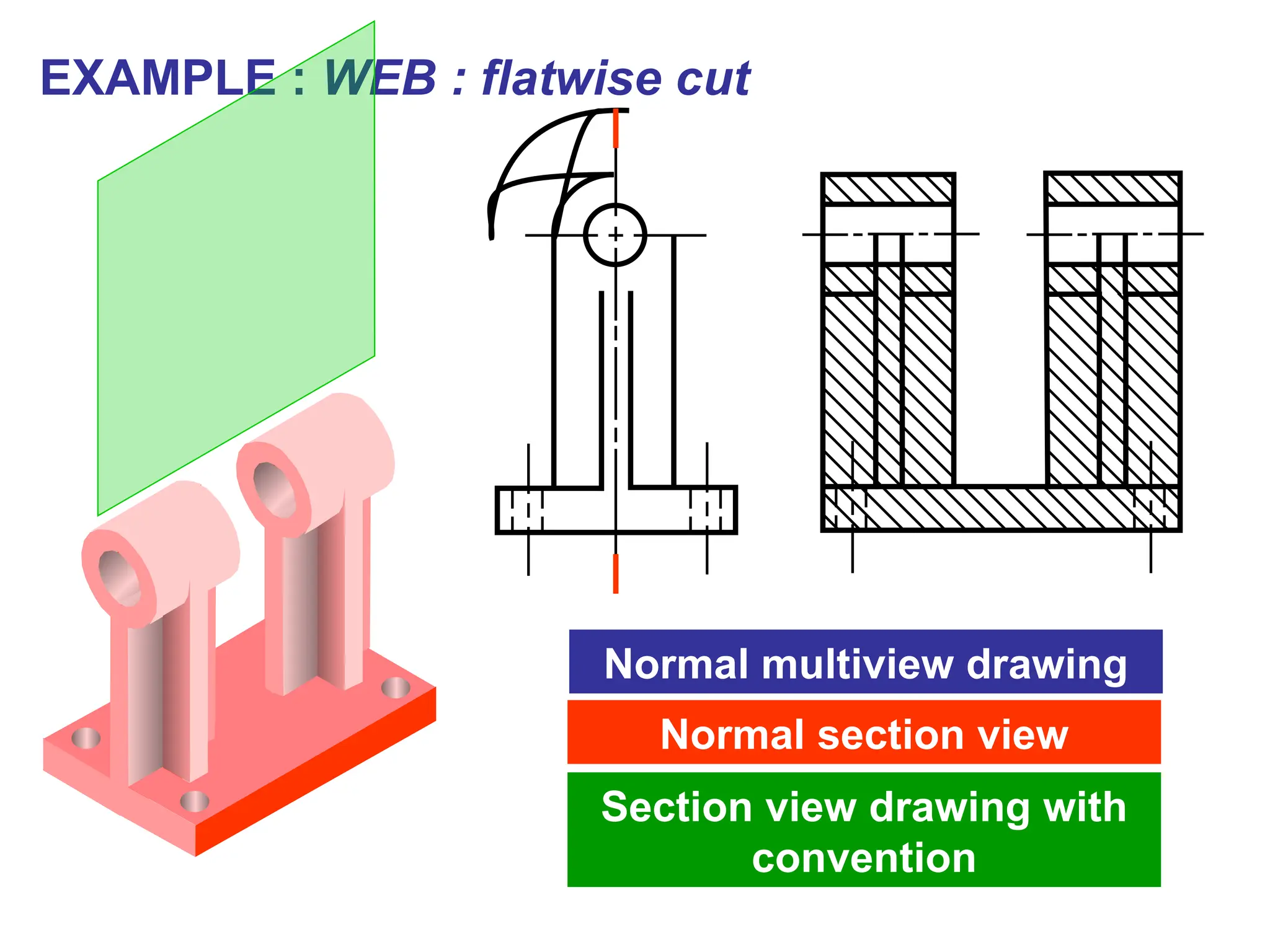
EXAMPLE : WEB: flatwise cut
Normal multiview drawing
Normal section view
Section view drawing with
convention
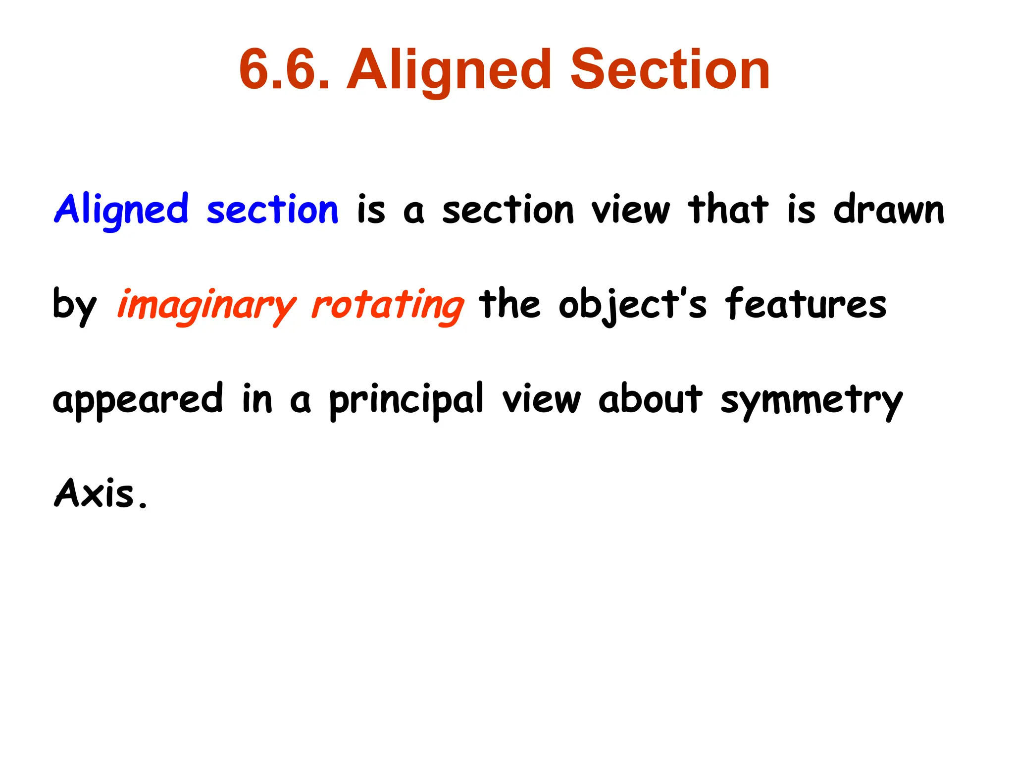
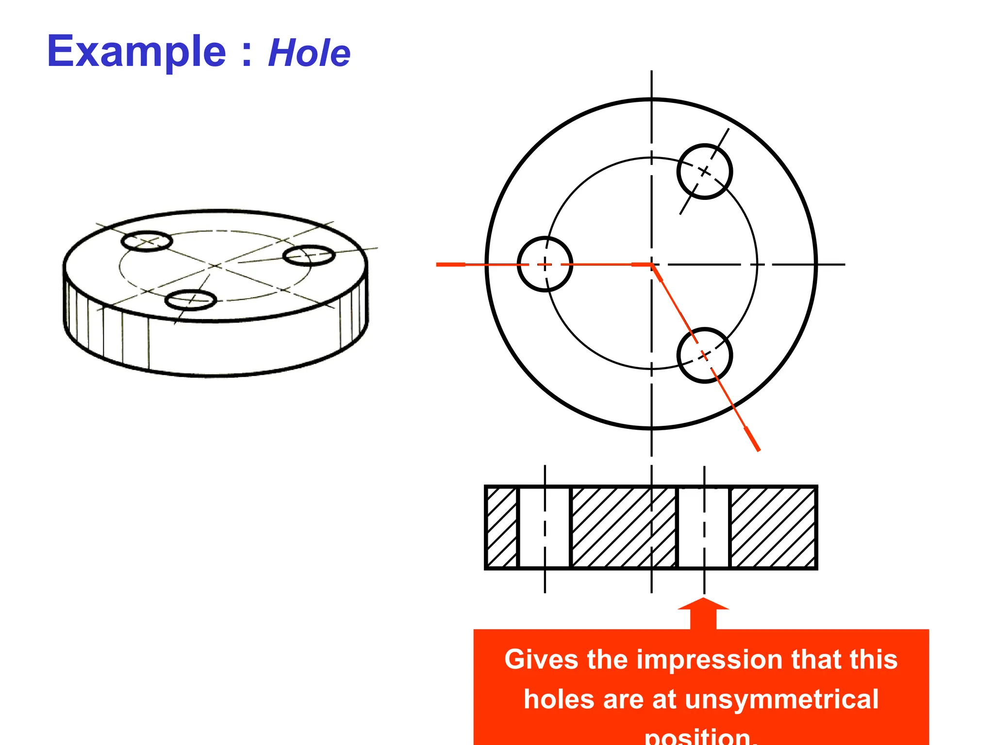
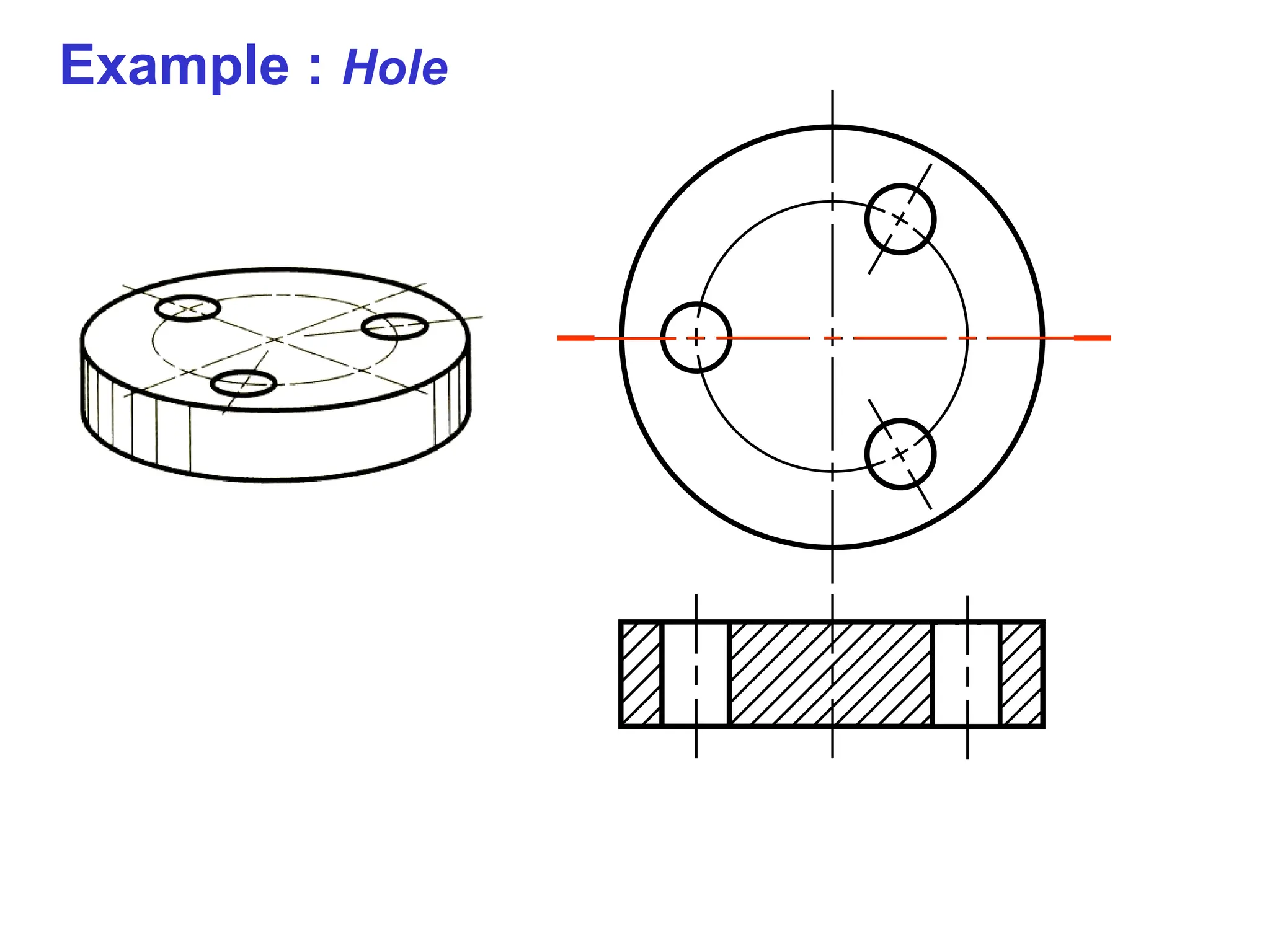
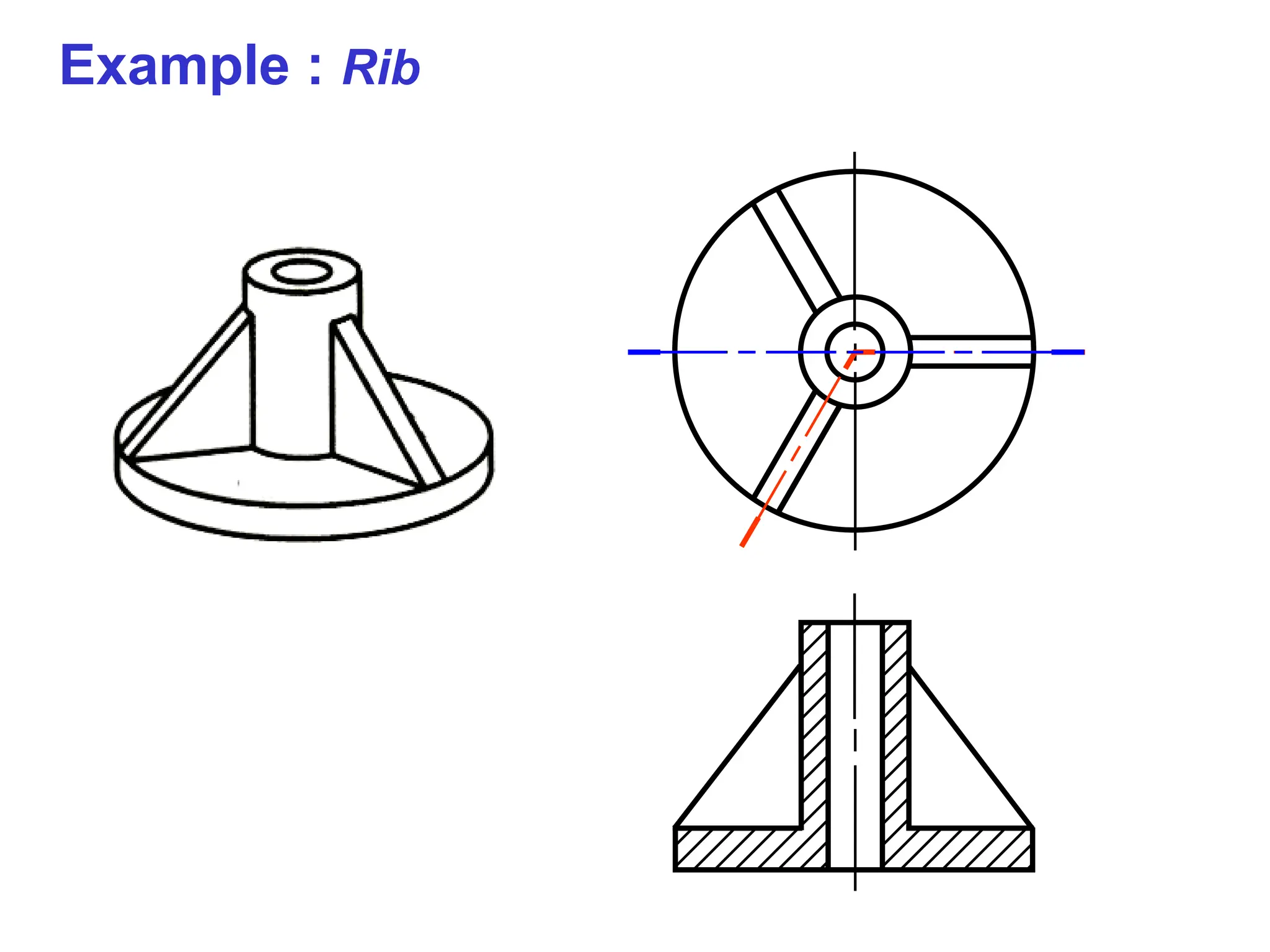
6.6. Aligned Section
Alignedsection is a section view that is drawn
by imaginary rotating the object’s features
appeared in a principal view about symmetry
Axis.