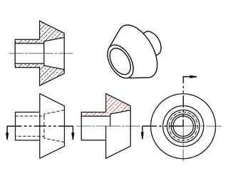
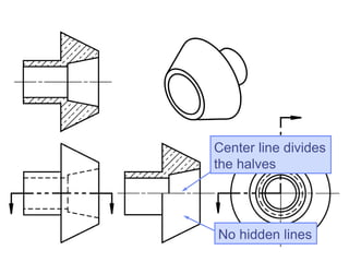
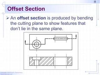
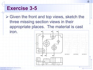
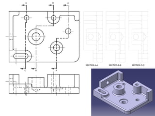
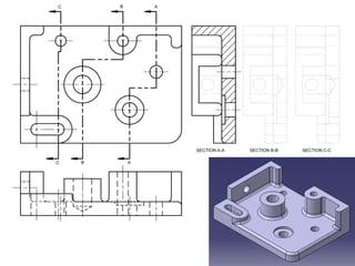
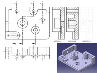
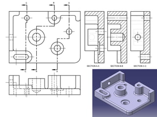
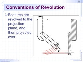
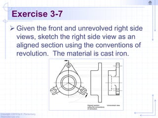
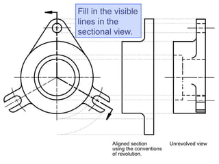
Copyright ©2010 by K. Plantenberg
Restricted use only
Chapter 3
Sectioning
Basic Topics
Advanced Topics
Exercises
Copyright ©2010 by K. Plantenberg
Restricted use only
Sectioning: Basic Topics
Summary
3.1) Sectional Views
3.2) Types of Sections
3.2.1) Full section
3.2.2) Half section
3.2.3) Offset section
Copyright ©2010 by K. Plantenberg
Restricted use only
Sectioning: Advanced Topics
3.2) Types of Sections
3.2.4) Aligned section
3.2.5) Rib and web sections
3.2.6) Broken section
3.2.7) Removed section
3.2.8) Revolved section
3.2.9) Non-sectioned parts
3.2.10) Thin sections
Copyright ©2010 by K. Plantenberg
Restricted use only
Sectioning: Exercises
Exercise 3-2: Full section
Exercise 3-4: Half section
Exercise 3-5: Offset section
Exercise 3-7: Aligned section
Copyright ©2010 by K. Plantenberg
Restricted use only
Sectioning
Summary
Copyright ©2010 by K. Plantenberg
Restricted use only
Summary
 What will we learn in Chapter 3?
→ How to create various types of sectional
views. (Sectional views allow you to see
inside an object.)
 Key points
→ Using a sectional view can be very useful
for parts that have complex interior
geometry.
Copyright ©2010 by K. Plantenberg
Restricted use only
Sectioning
3.1) Sectional Views
Copyright ©2010 by K. Plantenberg
Restricted use only
Sectional Views
 A sectional view or section looks
inside an object.
→ Sections are used to clarify the interior
construction of a part that can not be clearly
described by hidden lines in exterior views.
→ By taking an imaginary cut through the
object and removing a portion, the inside
features may be seen more clearly.
Copyright ©2010 by K. Plantenberg
Restricted use only
Sectional Views
 What is this?
 An ugly rock?
Copyright ©2010 by K. Plantenberg
Restricted use only
Sectional Views
 A pretty rock?
Copyright ©2010 by K. Plantenberg
Restricted use only
Creating a Section View
The part is cut
using an imaginary
cutting plane.
Copyright ©2010 by K. Plantenberg
Restricted use only
Creating a Section View
 The unwanted portion is mentally discarded
exposing the interior construction.
Copyright ©2010 by K. Plantenberg
Restricted use only
Section Example
Notice how the
cutting plane is
indicated.
Notice how the
cut material is
shown.
Sectional view label
Copyright ©2010 by K. Plantenberg
Restricted use only
Lines Used in Section Views
 Cutting Plane Line: Used to show where
the object is being cut.
→ (Phantom line type)
Copyright ©2010 by K. Plantenberg
Restricted use only
Lines Used in Section Views
Shows where
the part is being
cut.
Arrows point to
the portion being
kept.
Section
Lines
Copyright ©2010 by K. Plantenberg
Restricted use only
Lines Used in Section Views
 Section Lines: Section lines are used to
indicate where the cutting plane cuts the
material.
→ Section lines are thin lines.
→ Section line symbols are chosen according
to the material of the object
→ Section lines are generally drawn at a 45
angle.
Copyright ©2010 by K. Plantenberg
Restricted use only
Lines Used in Section Views
Common Section Line Symbols
Copyright ©2010 by K. Plantenberg
Restricted use only
Lines Used in Section Views
Common Section Line Symbols
More section line symbols shown in Fig. 3-4
Copyright ©2010 by K. Plantenberg
Restricted use only
Rules of Sectioning
 Rule 1:
A section
lined area is
always
completely
bounded by a
visible outline.
Copyright ©2010 by K. Plantenberg
Restricted use only
Rules of Sectioning
 Rule 2:
The section lines in
all areas should be
parallel.
→ Section lines
shown in opposite
directions indicate
a different part.
Copyright ©2010 by K. Plantenberg
Restricted use only
Rules of Sectioning
 Rule 3: All the visible edges behind the
cutting plane should be shown.
Copyright ©2010 by K. Plantenberg
Restricted use only
Rules of Sectioning
 Rule 4:
Hidden features should
be omitted in all areas of
a section view.
→ Exceptions include
threads and broken out
sections.
Copyright ©2010 by K. Plantenberg
Restricted use only
Sectioning
3.2) Types of Sections
Copyright ©2010 by K. Plantenberg
Restricted use only
Types of Sections
The type of section used depends on
the situation and what information
needs to be conveyed.
Types of sections
→Full Section
→Half Section
→Offset Section
→etc …
Copyright ©2010 by K. Plantenberg
Restricted use only
Full Section
 To create a full section, the cutting plane
passes fully through the object.
→ Used in many cases to avoid having to
dimension hidden lines.
Copyright ©2010 by K. Plantenberg
Restricted use only
Exercise 3-2
Full Section
Copyright ©2010 by K. Plantenberg
Restricted use only
Exercise 3-2
 Given the top and right side views, sketch
the front view as a full section.
→ The material used is steel.
Fill in the visible lines in the front full sectional view
Fill in the section lines in the front full sectional view
Section lines are
bounded by
visible lines
Visible features
behind the cutting
plane are shown.
Copyright ©2010 by K. Plantenberg
Restricted use only
Half Section
 A half
section
exposes the
interior of one
half of an
object while
retaining the
exterior of the
other half.
Copyright ©2010 by K. Plantenberg
Restricted use only
Half Section
 Half sections
are used
mainly for
symmetric
objects or
assembly
drawings.
Copyright ©2010 by K. Plantenberg
Restricted use only
Half Section
 A centerline
is used to
separate the
two halves.
 Hidden lines
should not be
shown on
either half.
Copyright ©2010 by K. Plantenberg
Restricted use only
Exercise 3-4
Half Section
Copyright ©2010 by K. Plantenberg
Restricted use only
Exercise 3-4
 Given the front and right side views,
sketch the top view as a full section and
create a half sectioned front view.
→ The material is brass.
Fill in the visible lines in the top full section view.
Fill in the section lines in the top full section view.
Fill in the visible lines in the right side half section view.
Fill in the section lines in the right side half section view.
No hidden lines
Center line divides
the halves
Copyright ©2010 by K. Plantenberg
Restricted use only
Offset Section
 An offset section is produced by bending
the cutting plane to show features that
don’t lie in the same plane.
Copyright ©2010 by K. Plantenberg
Restricted use only
Exercise 3-5
Offset Section
Copyright ©2010 by K. Plantenberg
Restricted use only
Exercise 3-5
 Given the front and top views, sketch the
three missing section views in their
appropriate places. The material is cast
iron.
Copyright ©2010 by K. Plantenberg
Restricted use only
Aligned Section
 In order to
include angled
elements in a
section, the
cutting plane
may be bent so
that it passes
through those
features.
Skip advanced topic
Copyright ©2010 by K. Plantenberg
Restricted use only
Conventions of Revolution
Features are
revolved to the
projection
plane, and
then projected
over.
Copyright ©2010 by K. Plantenberg
Restricted use only
Exercise 3-7
Aligned Section
Copyright ©2010 by K. Plantenberg
Restricted use only
Exercise 3-7
 Given the front and unrevolved right side
views, sketch the right side view as an
aligned section using the conventions of
revolution. The material is cast iron.
Fill in the visible
lines in the
sectional view.
Fill in the
section lines.
Notice how much clearer
the sectional view is.
Copyright ©2010 by K. Plantenberg
Restricted use only
Rib and Web Sections
 To avoid a false
impression of
thickness and
solidity, ribs and
webs are not
sectioned.
Cutting
plane
passes
through
the web
No section
lines in cut
area of
web
Copyright ©2010 by K. Plantenberg
Restricted use only
Rib and Web Sections
If the cutting
plane passes
crosswise through
the rib or web, we
include section
lines.
Cutting
plane passes
through the
web
Section
lines in cut
area of
web
Copyright ©2010 by K. Plantenberg
Restricted use only
Broken Section
 Sometimes only a partial or broken out
section is needed.
→ Hidden lines are shown in the non-sectioned
area of a broken section.
Copyright ©2010 by K. Plantenberg
Restricted use only
Removed Section
 A removed
section is
one that is
not in direct
projection of
the view
containing
the cutting
plane.
Copyright ©2010 by K. Plantenberg
Restricted use only
Revolved Section
 The cross sectional shape of an object
may be shown in the longitudinal view by
means of a revolved section.
Copyright ©2010 by K. Plantenberg
Restricted use only
Non – Sectioned Parts
 It is common practice to show standard
parts 'in the round' or un-sectioned.
→ Nuts
→ Bolts
→ Rivets
→ Shafts
→ Screws
Copyright ©2010 by K. Plantenberg
Restricted use only
Thin Sections
For extremely thin parts of less than 4
mm thickness, the parts should be
shown in solid black or without section
lines.
→ Sheet metal
→ Washers
→ Gaskets
Copyright ©2010 by K. Plantenberg
Restricted use only
Sectioning
The End

Chapter 5.pdf

  • 1.
    Copyright ©2010 byK. Plantenberg Restricted use only Chapter 3 Sectioning Basic Topics Advanced Topics Exercises
  • 2.
    Copyright ©2010 byK. Plantenberg Restricted use only Sectioning: Basic Topics Summary 3.1) Sectional Views 3.2) Types of Sections 3.2.1) Full section 3.2.2) Half section 3.2.3) Offset section
  • 3.
    Copyright ©2010 byK. Plantenberg Restricted use only Sectioning: Advanced Topics 3.2) Types of Sections 3.2.4) Aligned section 3.2.5) Rib and web sections 3.2.6) Broken section 3.2.7) Removed section 3.2.8) Revolved section 3.2.9) Non-sectioned parts 3.2.10) Thin sections
  • 4.
    Copyright ©2010 byK. Plantenberg Restricted use only Sectioning: Exercises Exercise 3-2: Full section Exercise 3-4: Half section Exercise 3-5: Offset section Exercise 3-7: Aligned section
  • 5.
    Copyright ©2010 byK. Plantenberg Restricted use only Sectioning Summary
  • 6.
    Copyright ©2010 byK. Plantenberg Restricted use only Summary  What will we learn in Chapter 3? → How to create various types of sectional views. (Sectional views allow you to see inside an object.)  Key points → Using a sectional view can be very useful for parts that have complex interior geometry.
  • 7.
    Copyright ©2010 byK. Plantenberg Restricted use only Sectioning 3.1) Sectional Views
  • 8.
    Copyright ©2010 byK. Plantenberg Restricted use only Sectional Views  A sectional view or section looks inside an object. → Sections are used to clarify the interior construction of a part that can not be clearly described by hidden lines in exterior views. → By taking an imaginary cut through the object and removing a portion, the inside features may be seen more clearly.
  • 9.
    Copyright ©2010 byK. Plantenberg Restricted use only Sectional Views  What is this?  An ugly rock?
  • 10.
    Copyright ©2010 byK. Plantenberg Restricted use only Sectional Views  A pretty rock?
  • 11.
    Copyright ©2010 byK. Plantenberg Restricted use only Creating a Section View The part is cut using an imaginary cutting plane.
  • 12.
    Copyright ©2010 byK. Plantenberg Restricted use only Creating a Section View  The unwanted portion is mentally discarded exposing the interior construction.
  • 13.
    Copyright ©2010 byK. Plantenberg Restricted use only Section Example Notice how the cutting plane is indicated. Notice how the cut material is shown. Sectional view label
  • 14.
    Copyright ©2010 byK. Plantenberg Restricted use only Lines Used in Section Views  Cutting Plane Line: Used to show where the object is being cut. → (Phantom line type)
  • 15.
    Copyright ©2010 byK. Plantenberg Restricted use only Lines Used in Section Views Shows where the part is being cut. Arrows point to the portion being kept. Section Lines
  • 16.
    Copyright ©2010 byK. Plantenberg Restricted use only Lines Used in Section Views  Section Lines: Section lines are used to indicate where the cutting plane cuts the material. → Section lines are thin lines. → Section line symbols are chosen according to the material of the object → Section lines are generally drawn at a 45 angle.
  • 17.
    Copyright ©2010 byK. Plantenberg Restricted use only Lines Used in Section Views Common Section Line Symbols
  • 18.
    Copyright ©2010 byK. Plantenberg Restricted use only Lines Used in Section Views Common Section Line Symbols More section line symbols shown in Fig. 3-4
  • 19.
    Copyright ©2010 byK. Plantenberg Restricted use only Rules of Sectioning  Rule 1: A section lined area is always completely bounded by a visible outline.
  • 20.
    Copyright ©2010 byK. Plantenberg Restricted use only Rules of Sectioning  Rule 2: The section lines in all areas should be parallel. → Section lines shown in opposite directions indicate a different part.
  • 21.
    Copyright ©2010 byK. Plantenberg Restricted use only Rules of Sectioning  Rule 3: All the visible edges behind the cutting plane should be shown.
  • 22.
    Copyright ©2010 byK. Plantenberg Restricted use only Rules of Sectioning  Rule 4: Hidden features should be omitted in all areas of a section view. → Exceptions include threads and broken out sections.
  • 23.
    Copyright ©2010 byK. Plantenberg Restricted use only Sectioning 3.2) Types of Sections
  • 24.
    Copyright ©2010 byK. Plantenberg Restricted use only Types of Sections The type of section used depends on the situation and what information needs to be conveyed. Types of sections →Full Section →Half Section →Offset Section →etc …
  • 25.
    Copyright ©2010 byK. Plantenberg Restricted use only Full Section  To create a full section, the cutting plane passes fully through the object. → Used in many cases to avoid having to dimension hidden lines.
  • 26.
    Copyright ©2010 byK. Plantenberg Restricted use only Exercise 3-2 Full Section
  • 27.
    Copyright ©2010 byK. Plantenberg Restricted use only Exercise 3-2  Given the top and right side views, sketch the front view as a full section. → The material used is steel.
  • 28.
    Fill in thevisible lines in the front full sectional view
  • 30.
    Fill in thesection lines in the front full sectional view
  • 32.
    Section lines are boundedby visible lines Visible features behind the cutting plane are shown.
  • 33.
    Copyright ©2010 byK. Plantenberg Restricted use only Half Section  A half section exposes the interior of one half of an object while retaining the exterior of the other half.
  • 34.
    Copyright ©2010 byK. Plantenberg Restricted use only Half Section  Half sections are used mainly for symmetric objects or assembly drawings.
  • 35.
    Copyright ©2010 byK. Plantenberg Restricted use only Half Section  A centerline is used to separate the two halves.  Hidden lines should not be shown on either half.
  • 36.
    Copyright ©2010 byK. Plantenberg Restricted use only Exercise 3-4 Half Section
  • 37.
    Copyright ©2010 byK. Plantenberg Restricted use only Exercise 3-4  Given the front and right side views, sketch the top view as a full section and create a half sectioned front view. → The material is brass.
  • 38.
    Fill in thevisible lines in the top full section view.
  • 40.
    Fill in thesection lines in the top full section view.
  • 42.
    Fill in thevisible lines in the right side half section view.
  • 44.
    Fill in thesection lines in the right side half section view.
  • 46.
    No hidden lines Centerline divides the halves
  • 47.
    Copyright ©2010 byK. Plantenberg Restricted use only Offset Section  An offset section is produced by bending the cutting plane to show features that don’t lie in the same plane.
  • 48.
    Copyright ©2010 byK. Plantenberg Restricted use only Exercise 3-5 Offset Section
  • 49.
    Copyright ©2010 byK. Plantenberg Restricted use only Exercise 3-5  Given the front and top views, sketch the three missing section views in their appropriate places. The material is cast iron.
  • 54.
    Copyright ©2010 byK. Plantenberg Restricted use only Aligned Section  In order to include angled elements in a section, the cutting plane may be bent so that it passes through those features. Skip advanced topic
  • 55.
    Copyright ©2010 byK. Plantenberg Restricted use only Conventions of Revolution Features are revolved to the projection plane, and then projected over.
  • 56.
    Copyright ©2010 byK. Plantenberg Restricted use only Exercise 3-7 Aligned Section
  • 57.
    Copyright ©2010 byK. Plantenberg Restricted use only Exercise 3-7  Given the front and unrevolved right side views, sketch the right side view as an aligned section using the conventions of revolution. The material is cast iron.
  • 58.
    Fill in thevisible lines in the sectional view.
  • 59.
  • 60.
    Notice how muchclearer the sectional view is.
  • 61.
    Copyright ©2010 byK. Plantenberg Restricted use only Rib and Web Sections  To avoid a false impression of thickness and solidity, ribs and webs are not sectioned. Cutting plane passes through the web No section lines in cut area of web
  • 62.
    Copyright ©2010 byK. Plantenberg Restricted use only Rib and Web Sections If the cutting plane passes crosswise through the rib or web, we include section lines. Cutting plane passes through the web Section lines in cut area of web
  • 63.
    Copyright ©2010 byK. Plantenberg Restricted use only Broken Section  Sometimes only a partial or broken out section is needed. → Hidden lines are shown in the non-sectioned area of a broken section.
  • 64.
    Copyright ©2010 byK. Plantenberg Restricted use only Removed Section  A removed section is one that is not in direct projection of the view containing the cutting plane.
  • 65.
    Copyright ©2010 byK. Plantenberg Restricted use only Revolved Section  The cross sectional shape of an object may be shown in the longitudinal view by means of a revolved section.
  • 66.
    Copyright ©2010 byK. Plantenberg Restricted use only Non – Sectioned Parts  It is common practice to show standard parts 'in the round' or un-sectioned. → Nuts → Bolts → Rivets → Shafts → Screws
  • 67.
    Copyright ©2010 byK. Plantenberg Restricted use only Thin Sections For extremely thin parts of less than 4 mm thickness, the parts should be shown in solid black or without section lines. → Sheet metal → Washers → Gaskets
  • 68.
    Copyright ©2010 byK. Plantenberg Restricted use only Sectioning The End