SECTIONING








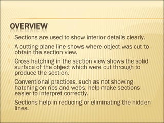
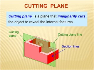
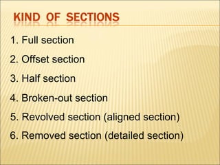
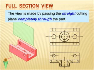
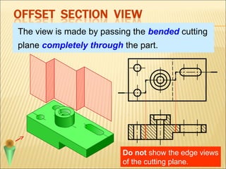
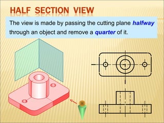
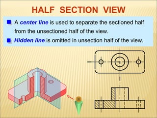
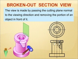
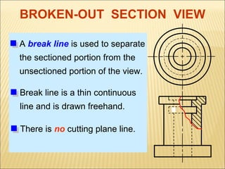
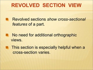
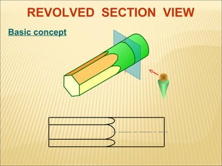
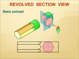
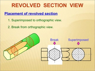
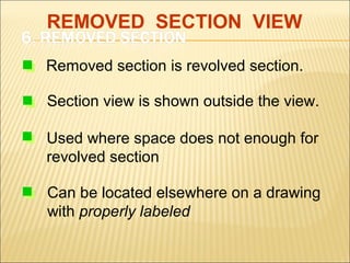
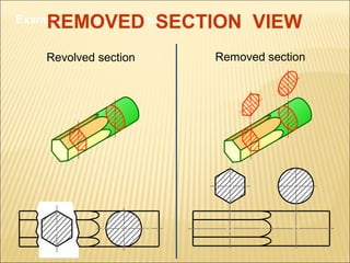
Sections are used to show interior details clearly.
A cutting-plane line shows where object was cut to
obtain the section view.
Cross hatching in the section view shows the solid
surface of the object which were cut through to
produce the section.
Conventional practices, such as not showing
hatching on ribs and webs, help make sections
easier to interpret correctly.
Sections help in reducing or eliminating the hidden
lines.
CUTTING PLANE
Cutting plane is a plane that imaginarily cuts
the object to reveal the internal features.
Cutting
plane

Cutting plane line

Section lines
SECTION LINES SYMBOLS
The section lines are different for each of
material’s type.
For practical purpose, the cast iron symbol is
used most often for any materials.

Cast iron,
Malleable iron

Steel

Concrete

Sand

Wood


Not Sectioned – show all exterior features for:










Shafts
Bearings, roller or ball
Gear Teeth
Threaded Fasteners, Nuts and Bolts
Rivets
Ribs
Washers
Keys and Pins
Springs
1. Full section
2. Offset section
3. Half section
4. Broken-out section
5. Revolved section (aligned section)
6. Removed section (detailed section)
The view is made by passing the straight cutting
plane completely through the part.
The view is made by passing the bended cutting
plane completely through the part.

Do not show the edge views
of the cutting plane.
The view is made by passing the cutting plane halfway
through an object and remove a quarter of it.
HALF SECTION VIEW
A center line is used to separate the sectioned half
from the unsectioned half of the view.
Hidden line is omitted in unsection half of the view.
BROKEN-OUT SECTION VIEW
The view is made by passing the cutting plane normal
to the viewing direction and removing the portion of an
object in front of it.
BROKEN-OUT SECTION VIEW
A break line is used to separate
the sectioned portion from the
unsectioned portion of the view.
Break line is a thin continuous
line and is drawn freehand.
There is no cutting plane line.
REVOLVED SECTION VIEW
Revolved sections show cross-sectional
features of a part.
No need for additional orthographic
views.
This section is especially helpful when a
cross-section varies.
REVOLVED SECTION VIEW
Basic concept
REVOLVED SECTION VIEW
Basic concept
REVOLVED SECTION VIEW
Placement of revolved section
1. Superimposed to orthographic view.
2. Break from orthographic view.

Break

Superimposed
REMOVED SECTION VIEW
Removed section is revolved section.
Section view is shown outside the view.
Used where space does not enough for
revolved section
Can be located elsewhere on a drawing
with properly labeled
REMOVED SECTION VIEW

Example : Revolved vs. removed sections.
Revolved section

Removed section
SECTIONING IN ENGG DRAWING

SECTIONING IN ENGG DRAWING

  • 1.
  • 2.
         Sections are usedto show interior details clearly. A cutting-plane line shows where object was cut to obtain the section view. Cross hatching in the section view shows the solid surface of the object which were cut through to produce the section. Conventional practices, such as not showing hatching on ribs and webs, help make sections easier to interpret correctly. Sections help in reducing or eliminating the hidden lines.
  • 3.
    CUTTING PLANE Cutting planeis a plane that imaginarily cuts the object to reveal the internal features. Cutting plane Cutting plane line Section lines
  • 4.
    SECTION LINES SYMBOLS Thesection lines are different for each of material’s type. For practical purpose, the cast iron symbol is used most often for any materials. Cast iron, Malleable iron Steel Concrete Sand Wood
  • 5.
     Not Sectioned –show all exterior features for:          Shafts Bearings, roller or ball Gear Teeth Threaded Fasteners, Nuts and Bolts Rivets Ribs Washers Keys and Pins Springs
  • 6.
    1. Full section 2.Offset section 3. Half section 4. Broken-out section 5. Revolved section (aligned section) 6. Removed section (detailed section)
  • 7.
    The view ismade by passing the straight cutting plane completely through the part.
  • 8.
    The view ismade by passing the bended cutting plane completely through the part. Do not show the edge views of the cutting plane.
  • 9.
    The view ismade by passing the cutting plane halfway through an object and remove a quarter of it.
  • 10.
    HALF SECTION VIEW Acenter line is used to separate the sectioned half from the unsectioned half of the view. Hidden line is omitted in unsection half of the view.
  • 11.
    BROKEN-OUT SECTION VIEW Theview is made by passing the cutting plane normal to the viewing direction and removing the portion of an object in front of it.
  • 12.
    BROKEN-OUT SECTION VIEW Abreak line is used to separate the sectioned portion from the unsectioned portion of the view. Break line is a thin continuous line and is drawn freehand. There is no cutting plane line.
  • 13.
    REVOLVED SECTION VIEW Revolvedsections show cross-sectional features of a part. No need for additional orthographic views. This section is especially helpful when a cross-section varies.
  • 14.
  • 15.
  • 16.
    REVOLVED SECTION VIEW Placementof revolved section 1. Superimposed to orthographic view. 2. Break from orthographic view. Break Superimposed
  • 17.
    REMOVED SECTION VIEW Removedsection is revolved section. Section view is shown outside the view. Used where space does not enough for revolved section Can be located elsewhere on a drawing with properly labeled
  • 18.
    REMOVED SECTION VIEW Example: Revolved vs. removed sections. Revolved section Removed section

Editor's Notes

  • #6 Instructor: Go through the list with your students and see if there is something missing. Springs are another item that are not normally sectioned. This would come out of their reading.