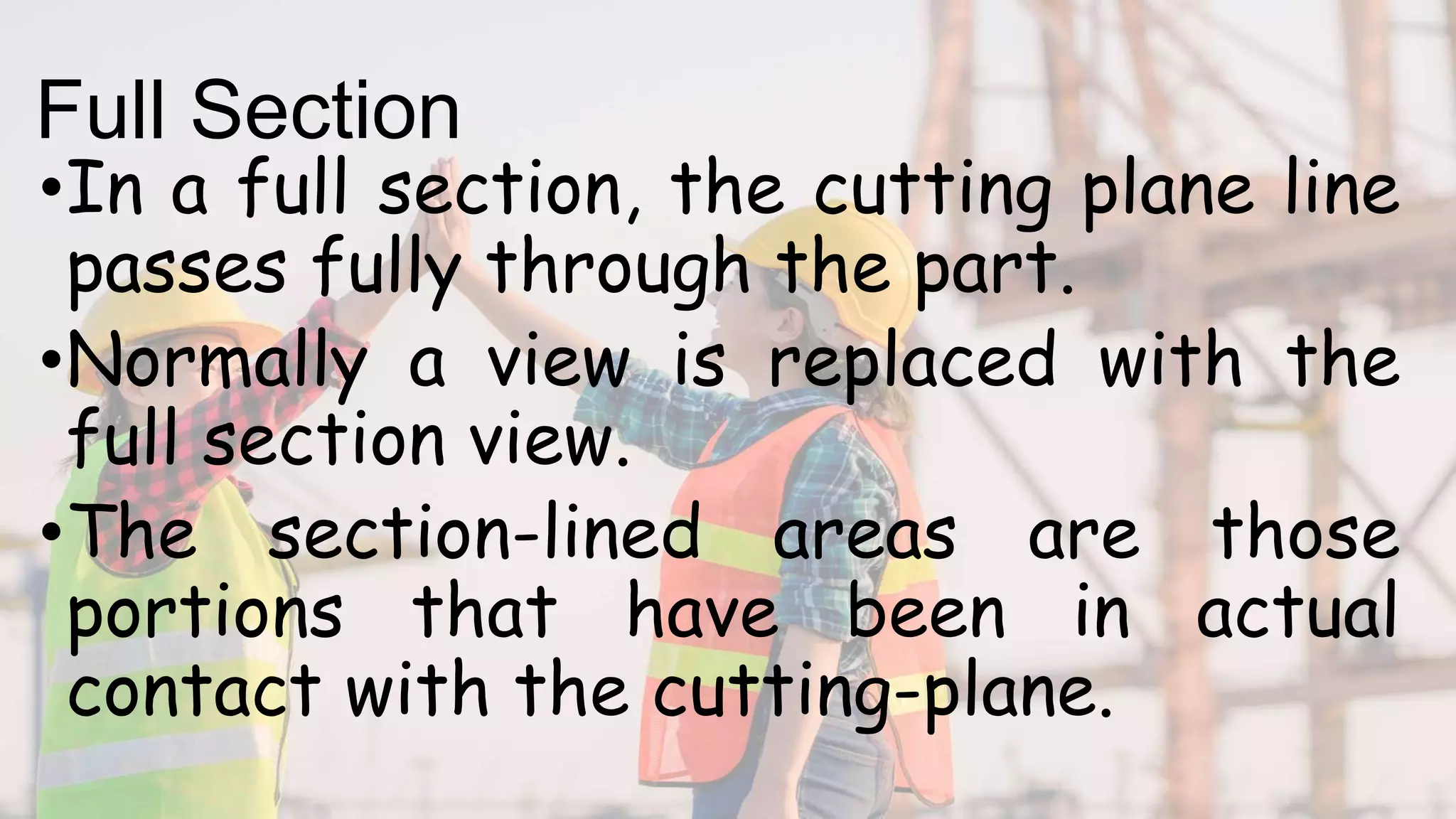
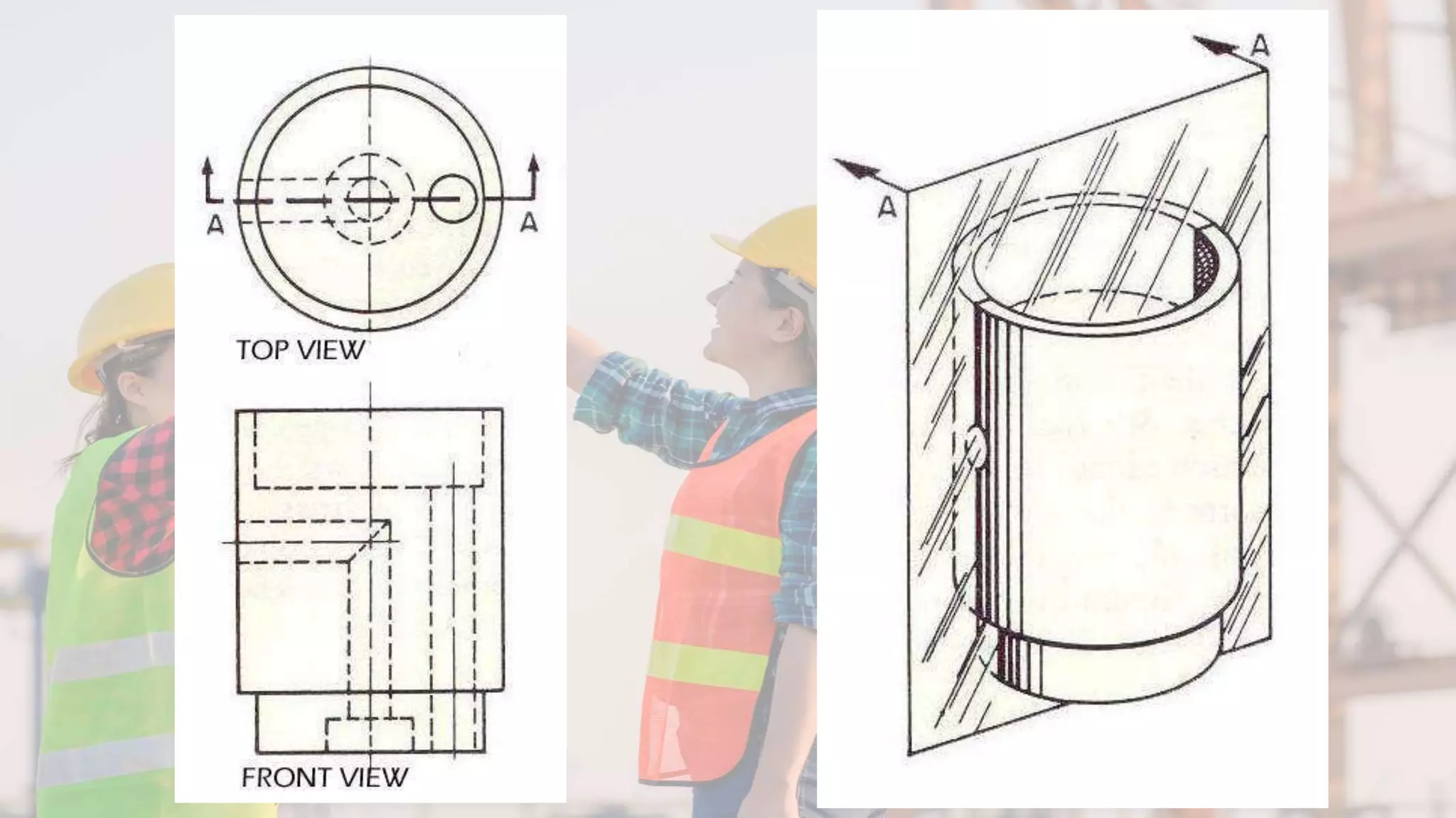
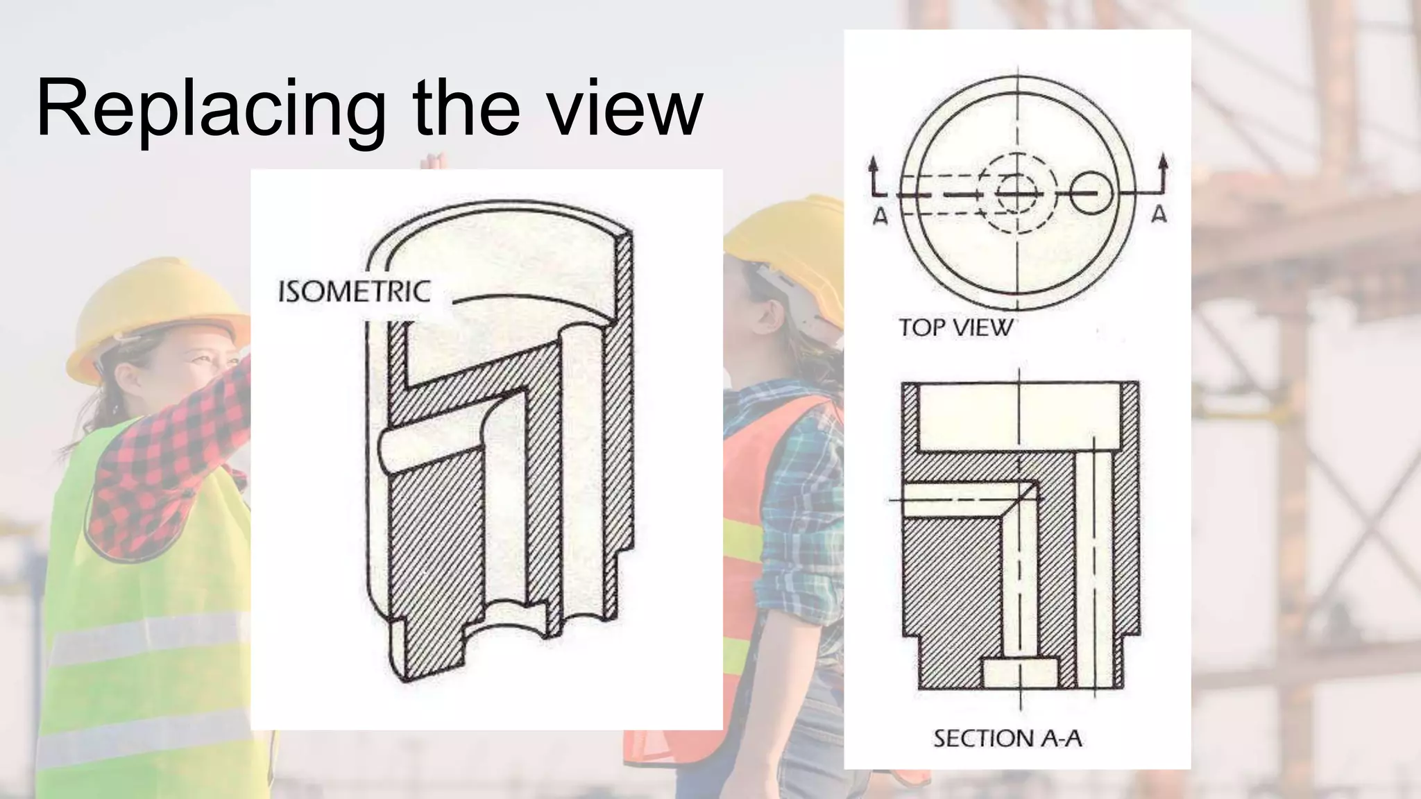
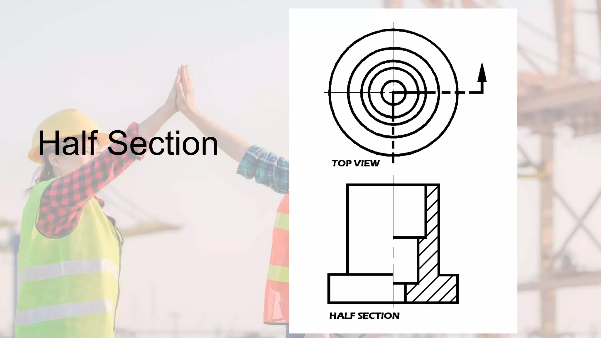
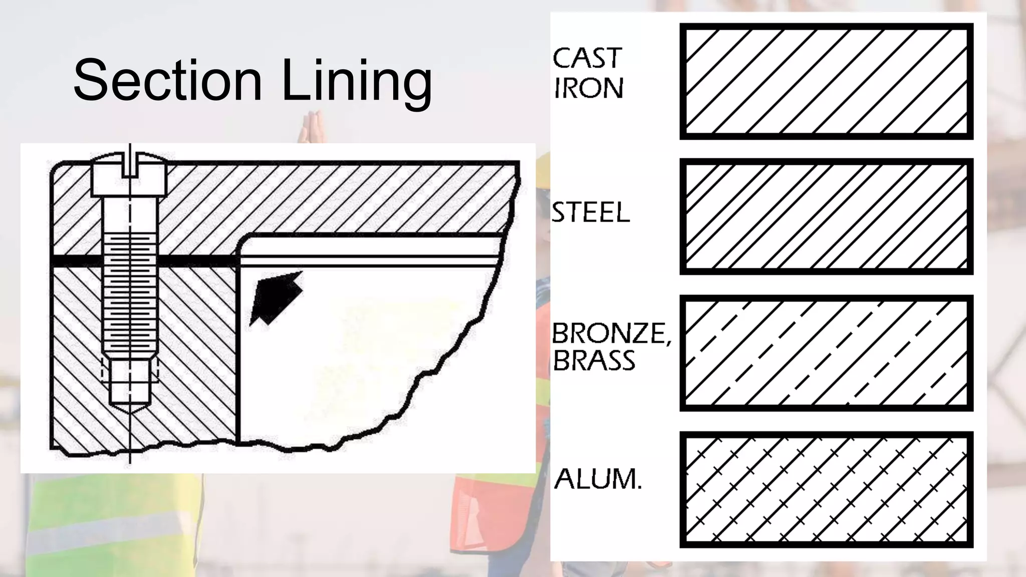
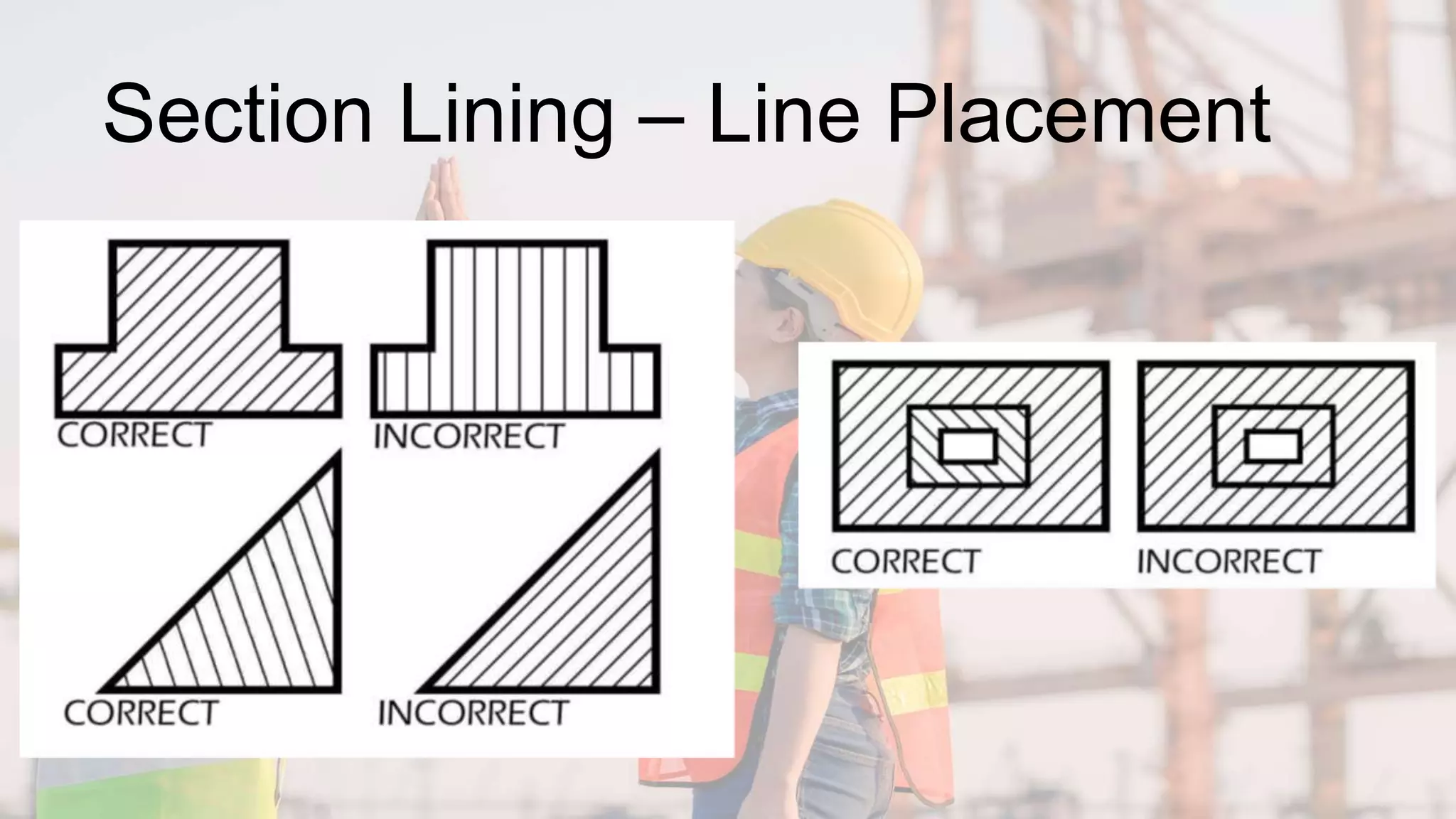
Drawing
Section Views
What is a “Section View”?
•A section view is a view used on a drawing to
show an area or hidden part of an object by
cutting away or removing some of that object.
•The cut line is called a “cutting plane” and can
be done in several ways.
•The following slides will help show the several
methods or types of “section views”
Visualizing the Cutting Plane
•It is very important to Visualize what the
part will look like after it is cut open.
•Choosing the type of section and location
of the cutting plane.
•Making the cut and drawing the view in the
proper location.
Full Section
•In a full section, the cutting plane line
passes fully through the part.
•Normally a view is replaced with the
full section view.
•The section-lined areas are those
portions that have been in actual
contact with the cutting-plane.
Replacing the view
Half Section
•Half Section is used to the exterior and
interior of the part in the same view.
•The cutting-plane line cuts halfway
through the part and removes one quarter
of the material.
•The line that separates the different
types (interior and exterior) may be a
centerline or a visible line.
Half Section
Section Lining
•Materials – Common materials
•The symbol for cast iron can be used for
most section views.
•Refer to any common drafting text for
additional symbols.
•45-degree angle lines should be used.
•1/8” between lines.
•All lines should be uniformly spaced
•Thin sections may be blackened in completely
•Spacing lines by eye increases speed
Section Lining
Section Lining – Line Placement
•Lines should never be parallel or
perpendicular to the object lines.
•If the outline of the object has 45-
degree lines, 30- or 60-degree lines
should be used.
•Assemblies with several parts should
be lined with varying angle section
lines.
Section Lining – Line Placement
Offset Sections
•Used to show parts and features that
do not line up with each other.
•Cutting-plane line does not travel in a
straight line.
•The offsets or bends in the cutting-
plane line do not show in the section.
•The versatility of this section makes it
very useful.
Offset
Sections
Aligned Sections
•Usually used on symmetrical circular
parts.
•Place the cutting-plane line to show
the most detail.
•All parts and details are rotated into
the section view.
•Ribs and spokes can be left un-lined
for better clarity in the section view.
Aligned
Sections
Revolved Sections
•Used to show a small portion of a
drawing.
•Show a cross-section of an area turned
90 degrees or perpendicular to the
object.
•Put into a drawing to show an area not
normally shown.
Revolved Sections
Broken-out Sections
•Used to generate a section for a small
area without using a cutting-plane line.
•Removes a small amount of material to
show the interior details.
•Always used in an orthographic view.
•Used to enhance the orthographic view
by giving the viewer a better look at
key interior details.
Broken-out Sections
Sectioning Shafts
•Used to show a break in a longer part
allowing better used of drawing
surface.
•Gives the impression of a 3-D break on
the shaft.
•Adds a touch of flair to the drawing.
Sectioning Shafts
Assembly Sections
•Shows how parts fit together
•Allows better clarity with a
complicated assembly of parts.
•Shows how parts not only fit together
but allows for a visual view of how they
function.
Assembly Sections

Drawing Section Views_TD 8_w4.pptx

  • 1.
  • 2.
    What is a“Section View”? •A section view is a view used on a drawing to show an area or hidden part of an object by cutting away or removing some of that object. •The cut line is called a “cutting plane” and can be done in several ways. •The following slides will help show the several methods or types of “section views”
  • 3.
    Visualizing the CuttingPlane •It is very important to Visualize what the part will look like after it is cut open. •Choosing the type of section and location of the cutting plane. •Making the cut and drawing the view in the proper location.
  • 4.
    Full Section •In afull section, the cutting plane line passes fully through the part. •Normally a view is replaced with the full section view. •The section-lined areas are those portions that have been in actual contact with the cutting-plane.
  • 6.
  • 7.
    Half Section •Half Sectionis used to the exterior and interior of the part in the same view. •The cutting-plane line cuts halfway through the part and removes one quarter of the material. •The line that separates the different types (interior and exterior) may be a centerline or a visible line.
  • 8.
  • 9.
    Section Lining •Materials –Common materials •The symbol for cast iron can be used for most section views. •Refer to any common drafting text for additional symbols. •45-degree angle lines should be used. •1/8” between lines. •All lines should be uniformly spaced •Thin sections may be blackened in completely •Spacing lines by eye increases speed
  • 10.
  • 11.
    Section Lining –Line Placement •Lines should never be parallel or perpendicular to the object lines. •If the outline of the object has 45- degree lines, 30- or 60-degree lines should be used. •Assemblies with several parts should be lined with varying angle section lines.
  • 12.
    Section Lining –Line Placement
  • 13.
    Offset Sections •Used toshow parts and features that do not line up with each other. •Cutting-plane line does not travel in a straight line. •The offsets or bends in the cutting- plane line do not show in the section. •The versatility of this section makes it very useful.
  • 14.
  • 15.
    Aligned Sections •Usually usedon symmetrical circular parts. •Place the cutting-plane line to show the most detail. •All parts and details are rotated into the section view. •Ribs and spokes can be left un-lined for better clarity in the section view.
  • 16.
  • 17.
    Revolved Sections •Used toshow a small portion of a drawing. •Show a cross-section of an area turned 90 degrees or perpendicular to the object. •Put into a drawing to show an area not normally shown.
  • 18.
  • 19.
    Broken-out Sections •Used togenerate a section for a small area without using a cutting-plane line. •Removes a small amount of material to show the interior details. •Always used in an orthographic view. •Used to enhance the orthographic view by giving the viewer a better look at key interior details.
  • 20.
  • 21.
    Sectioning Shafts •Used toshow a break in a longer part allowing better used of drawing surface. •Gives the impression of a 3-D break on the shaft. •Adds a touch of flair to the drawing.
  • 22.
  • 23.
    Assembly Sections •Shows howparts fit together •Allows better clarity with a complicated assembly of parts. •Shows how parts not only fit together but allows for a visual view of how they function.
  • 24.