Introduction to Artificial Intelligence and History of AI
under ground cable document
1. UNIT-VI
UNDER GROUND CABLES
INTRODUCTION
Electric power can be transmitted or distributed either by overhead
system or by underground cables. The underground cables have several
advantages such as less liable to damage through storms or lightning, low
maintenance cost, less chance of faults, smaller voltage drop and better general
appearance. However, their major drawback is that they have greater installation
cost and introduce insulation problems at high voltages compared with the
equivalent overhead system. For this reason, underground cables are employed
where it is impracticable to use overhead lines. Such locations may be thickly
populated areas where municipal authorities prohibit overhead lines for reasons
of safety, or around plants and substations or where maintenance conditions do
not permit the use of overhead construction. The chief use of underground
cables for many years has been for distribution of electric power in congested
urban areas at comparatively low or moderate voltages. However, recent
improvements in the design and manufacture have led to the development of
cables suitable for use at high voltages. This has made it possible to employ
underground cables for transmission of electric power for short or moderate
distances. In this chapter, we shall focus our attention on the various aspects of
underground cables and their increasing use in power system.
An underground cable essentially consists of one or more conductors
covered with suitable insulation and surrounded by a protecting cover. Although
several types of cables are available, the type of cable to be used will depend
upon the working voltage and service requirements. In general, a cable must
fulfill the following necessary requirements:
(i) The conductor used in cables should be tinned stranded copper or aluminum
of high conductivity. Stranding is done so that conductor may become flexible
and carry more current.
(ii) The conductor size should be such that the cable carries the desired load
current without overheating and causes voltage drop within permissible limits.
(iii) The cable must have proper thickness of insulation in order to give high
degree of safety and reliability at the voltage for which it is designed.
(iv) The cable must be provided with suitable mechanical protection so that it
may withstand the rough use in laying it.
(v) The materials used in the manufacture of cables should be such that there is
complete chemical and physical stability throughout.
CONSTRUCTION OF CABLES
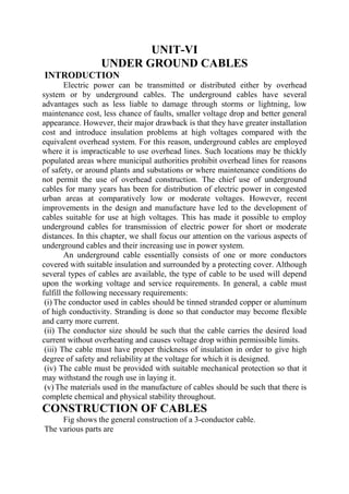
Fig shows the general construction of a 3-conductor cable.
The various parts are
2. a)Cores or Conductors
A cable may have one or more than one core (conductor) depending upon the
type of service for which it is intended. For instance, the 3- conductor cable
shown in Fig. is used for 3-phase service. The conductors are made of tinned
copper or aluminum and are usually stranded in order to provide flexibility to
the cable.
b) Insulation
Each core or conductor is provided with a suitable thickness of insulation, the
thickness of layer depending upon the voltage to be withstood by the cable. The
commonly used materials for insulation are impregnated paper, varnished
cambric or rubber mineral compound.
c)Metallic sheath.
In order to protect the cable from moisture, gases or other damaging liquids
(acids or alkalies) in the soil and atmosphere, a metallic sheath of lead or
aluminum is provided over the insulation as shown in Fig.
d) Bedding.
Over the metallic sheath is applied a layer of bedding which consists of a
fibrous material like jute or hessian tape. The purpose of bedding is to protect
the metallic sheath against corrosion and from mechanical injury due to
armouring.
e) Armouring.
Over the bedding, armouring is provided which consists of one or two layers of
galvanized steel wire or steel tape. Its purpose is to protect the cable from
mechanical injury while laying it and during the course of handling. Armouring
may not be done in the case of some cables.
f) Serving.
In order to protect armouring from atmospheric conditions, a layer of fibrous
material (like jute) similar to bedding is provided over the armouring. This is
known as serving.
3. It may not be out of place to mention here that bedding, armouring and serving
are only applied to the cables for the protection of conductor insulation and to
protect the metallic sheath from Mechanical injury.
1. INSULATING MATERIALS FOR CABLES
The satisfactory operation of a cable depends to a great extent upon the
characteristics of insulation used. Therefore, the proper choice of insulating
material for cables is of considerable importance. In general, the insulating
materials used in cables should have the following
Properties
(i) High insulation resistance to avoid leakage current.
(ii)High dielectric strength to avoid electrical breakdown of the cable.
(iii) High mechanical strength to withstand the mechanical handling of
cables.
(iv) Non-hygroscopici.e., it should not absorb moisture from air or soil.
The moisture tends to decrease the insulation resistance and hastens the
breakdown of the cable. In case the insulating material is hygroscopic, it
must be enclosed in a waterproof covering like lead sheath.
(v)Non-inflammable.
(vi)Low cost so as to make the underground system a viable proposition.
(vii) Unaffected by acids and alkalies to avoid any chemical action. No
one insulating material possesses all the above mentioned properties.
Therefore, the type of insulating material to be used depends upon the
purpose for which the cable is required and the quality of insulation to be
aimed at. The principal insulating materials used in cables are rubber,
vulcanized India rubber, impregnated paper, varnished cambric and
polyvinyl chloride.
Rubber
Rubber may be obtained from milky sap of tropical trees or it may be
produced from oil products. It has relative permittivity varying between 2 and 3,
dielectric strength is about 30 kV/mm and resistivity of insulation is 1017 cm.
Although pure rubber has reasonably high insulating properties, it suffers form
some major drawbacks viz., readily absorbs moisture, maximum safe
temperature is low (about 38ºC), soft and liable to damage due to rough
handling and ages when exposed to light. Therefore, pure rubber cannot be used
as an insulating material.
Vulcanised India Rubber (V.I.R.)
It is prepared by mixing pure rubber with mineral matter such as zinc
oxide, red lead etc., and 3 to 5% of sulphur. The compound so formed is rolled
into thin sheets and cut into strips. The rubber compound is then applied to the
conductor and is heated to a temperature of about 150ºC. The whole process is
called vulcanisation and the product obtained is known as vulcanised India
rubber. Vulcanised India rubber has greater mechanical strength, durability and
wear resistant property than pure rubber. Its main drawback is that sulphur
4. reacts very quickly with copper and for this reason, cables using VIR insulation
have tinned copper conductor. The VIR insulation is generally used for low and
moderate voltage cables.
Impregnated paper
It consists of chemically pulped paper made from wood chippings and
impregnated with some compound such as paraffinic or naphthenic material.
This type of insulation has almost superseded the rubber insulation. It is because
it has the advantages of low cost, low capacitance, high dielectric strength and
high insulation resistance. The only disadvantage is that paper is hygroscopic
and even if it is impregnated with suitable compound, it absorbs moisture and
thus lowers the insulation resistance of the cable. For this reason, paper
insulated cables are always provided with some protective covering and are
never left unsealed. If it is required to be left unused on the site during laying,
its ends are temporarily covered with wax or tar. Since the paper insulated
cables have the tendency to absorb moisture, they are used where the cable
route has a few joints. For instance, they can be profitably used for distribution
at low voltages in congested areas where the joints are generally provided only
at the terminal apparatus. However, for smaller installations, where the lengths
are small and joints are required at a number of places, VIR cables will be
cheaper and durable than paper insulated cables.
Varnished cambric
It is a cotton cloth impregnated and coated with varnish. This type of
insulation is also known as empire tape. The cambric is lapped on to the
conductor in the form of a tape and its surfaces are coated with petroleum jelly
compound to allow for the sliding of one turn over another as the cable is bent.
As the varnished cambric is hygroscopic, therefore, such cables are always
provided with metallic sheath. Its dielectric strength is about 4 kV/mm and
permittivity is 2.5 to 3.8.
Polyvinyl chloride (PVC)
This insulating material is a synthetic compound. It is obtained from the
polymerization of acetylene and is in the form of white powder. For obtaining
this material as a cable insulation, it is compounded with certain materials
known as plasticizers which are liquids with high boiling point. The plasticizer
forms a gell and renders the material plastic over the desired range of
temperature. Polyvinyl chloride has high insulation resistance, good dielectric
strength and mechanical toughness over a wide range of temperatures. It is inert
to oxygen and almost inert to many alkalies and acids. Therefore, this type of
insulation is preferred over VIR in extreme environmental conditions such as in
cement factory or chemical factory. As the mechanical properties (i.e., elasticity
etc.) of PVC are not so good as those of rubber, therefore, PVC insulated cables
are generally used for low and medium domestic lights and power installations.
5. CLASSIFICATION OF CABLES
Cables for underground service may be classified in two ways according to
(i) the type of insulating material used in their manufacture
(ii) the voltage for
which they are manufactured. However, the latter method of classification is
generally preferred, according to which cables can be divided into the following
groups:
Low-tension (L.T.) cables — upto 1000 V
High-tension (H.T.) cables — upto 11,000 V
Super-tension (S.T.) cables — from 22 kV to 33 kV
Extra high-tension (E.H.T.) cables — from 33 kV to 66 kV
Extra super voltage cables — beyond 132 kV
A cable may have one or more than one core depending upon the type of service
for which it is intended. It may be
(i) single-core
(ii) two-core
(iii) three-core
(iv) four-core etc.
For a 3-phase service, either 3-single-core cables or three-core cable can be
used depending upon the operating voltage and load demand. Fig. shows the
constructional details of a single-core low tension cable. The cable has ordinary
construction because the stresses developed in the cable for low voltages (up to
6600 V) are generally small. It consists of one circular core of tinned stranded
copper (or aluminium) insulated by layers of impregnated paper. The insulation
is surrounded by a lead sheath which prevents the entry of moisture into the
inner parts. In order to protect the lead sheath from corrosion, an overall serving
of compounded fibrous material (jute etc.) is provided. Single-core cables are
6. not usually armoured in order to avoid excessive sheath losses. The principal
advantages of single-core cables are simple construction and availability of
larger copper section .
Cable For 3-Phase
In practice, underground cables are generally required to deliver 3-phase
power. For the purpose, either three-core cable or three single core cables may
be used. For voltages upto 66 kV, 3-core cable (i.e., multi-core construction) is
preferred due to economic reasons. However, for voltages beyond 66 kV, 3-
core-cables become too large and unwieldy and, therefore, single-core cables
areused. The following types of cables are generally used for 3-phase service :
1.Belted cables — upto 11 kV
2.Screened cables — from 22 kV to 66 kV
3.Pressure cables — beyond 66 kV.
1. Belted Cables
These cables are used for voltages upto 11kV but in extraordinary cases,
their use may be extended upto 22kV. Fig.3 shows the constructional details of
a 3-core belted cable. The cores are insulated from each other by layers of
impregnated paper.
Another layer of impregnated paper tape, called paper belt is wound
round the grouped insulated cores. The gap between the insulated cores is filled
with fibrous insulating material (jute etc.) so as to give circular cross-section to
the cable. The cores are generally stranded and may be of non circular shape to
make better use of available space. The belt is covered with lead sheath to
protect the cable against ingress of moisture and mechanical injury. The lead
sheath is covered with one or more layers of armouring with an outer serving
(not shown in the figure).The belted type construction is suitable only for low
and medium voltages as the electro static stresses developed in the cables for
these voltages are more or less radial i.e., across the insulation. However, for
7. high voltages (beyond 22 kV), the tangential stresses also become important.
These stresses act along the layers of paper insulation. As the insulation
resistance of paper is quite small along the layers, therefore, tangential stresses
set up leakage current along the layers of paper insulation. The leakage current
causes local heating, resulting in the risk of breakdown of insulation at any
moment. In order to overcome this difficulty, screened cables are used where
leakage currents are conducted to earth through metallic screens.
2.Screened Cables
These cables are meant for use up to 33 kV, but in particular cases their
use may be extended to operating voltages up to 66 kV. Two principal types of
screened cables are H-type cables and S.L. type cables.
(i)H-type Cables
This type of cable was first designed by H. Hochstetler and hence the
name. Fig. shows the constructional details of a typical 3-core, H-type cable.
Each core is insulated by layers of impregnated paper. The insulation on each
core is covered with a metallic screen which usually consists of a perforated
aluminum foil. The cores are laid in such a way that metallic screens
Make contact with one another. An additional conducting belt (copper woven
fabric tape) is Wrapped round the three cores. The cable has no insulating belt
but lead sheath, bedding, armouring and serving follow as usual. It is easy to see
that each core screen is in electrical contact with the conducting belt and the
lead sheath. As all the four screens (3 core screens and one conducting belt) and
the lead sheath are at earth potential, therefore, the electrical stresses are purely
radial and consequently dielectric losses are reduced. Two principal advantages
are claimed for H-type cables. Firstly, the perforations in the metallic screens
assist in the complete impregnation of the cable with the compound and thus the
possibility of air pockets or voids (vacuous spaces) in the dielectric is
eliminated. The voids if present tend to reduce the breakdown strength of the
8. cable and may cause considerable damage to the paper insulation. Secondly, the
metallic screens increase the heat dissipating power of the cable.
(Ii) S.L Type cables
Fig. shows the constructional details of a 3-core S.L. (separate lead) type
cable. It is basically H-type cable but the screen round each core insulation is
covered by its own lead sheath. There is no overall lead sheath but only
armouring and serving are provided. The S.L. type cables have two main
advantages over H-type cables. Firstly, the separate sheaths minimize the
possibility of core-to-core breakdown. Secondly, bending of cables becomes
easy due to the elimination of overall lead sheath. However, the disadvantage is
that the three lead sheaths of S.L. cable are much thinner than the single sheath
of H-cable and, therefore, call for greater care in manufacture
3. Pressure cables
For voltages beyond 66 kV, solid type cables are unreliable because there
is a danger of breakdown of insulation due to the presence of voids. When the
operating voltages are greater than 66 kV, pressure cables are used. In such
cables, voids are eliminated by increasing the pressure of compound and for this
reason they are called pressure cables. Two types of pressure cables viz oil-
filled cables and gas pressure cables are commonly used.
(i)Oil-filled cables.
In such types of cables, channels or ducts are provided in the cable for oil
circulation. The oil under pressure (it is the same oil used for impregnation) is
kept constantly supplied to the channel by means of external reservoirs placed at
suitable distances (say 500 m) along the route of the cable. Oil under pressure
compresses the layers of paper insulation and is forced in to any voids that may
have formed between the layers. Due to the elimination of voids, oil-filled
cables can be used for higher voltages, the range being from 66 kV up to 230
kV. Oilfilled cables are of three types viz., single-core conductor channel,
single-core sheath channel and three-core filler-space channels.
9. Fig. shows the constructional details of a single-core conductor channel, oil
filled cable. The oil channel is formed at the center by stranding the conductor
wire around a hollow cylindrical steel spiral tape. The oil under pressure is
supplied to the channel by means of external reservoir. As the channel is made
of spiral steel tape, it allows the oil to percolate between copper strands to the
wrapped insulation. The oil pressure compresses the layers of paper insulation
and prevents the possibility of void formation. The system is so designed that
when the oil gets expanded due to increase in cable temperature, the extra oil
collects in the reservoir. However, when the cable temperature falls during light
load conditions, the oil from the reservoir flows to the channel. The
disadvantage of this type of cable is that the channel is at the middle of the cable
and is at full voltage w.r.t. earth, so that a very complicated system of joints is
necessary. Fig. shows the constructional details of a single core sheath channel
oil-filled cable. In this type of cable, the conductor is solid similar to that of
solid cable and is paper insulated. However, oil ducts are provided in them
etallic sheath as shown. In the 3-core oil-filler cable shown in Fig. the oil ducts
are located in the filler spaces. These channels are composed of perforated
metalribbon tubing and are at earth potential.
10. (ii)Gas Pressure Cable
The voltage required to set up ionization inside a void increases as the pressure
is increased. Therefore, if ordinary cable is subjected to a sufficiently high
pressure, the ionization can be altogether eliminated. At the same time, the
increased pressure produces radial compression which tends to close any voids.
This is the underlying principle of gas pressure cables.
Fig Shows the section of external pressure cable designed by Hochstetler, Vogal
and Bowden. The construction of the cable is similar to that of an ordinary solid
type except that it is of triangular shape and thickness of lead sheath is 75% that
of solid cable. The triangular section reduces the weight and gives low thermal
resistance but the main reason for triangular shape is that the lead sheath acts as
a pressure membrane. The sheath is protected by a thin metal tape. The cable is
laid in a gas-tight steel pipe. The pipe is filled with dry nitrogen gas at 12 to 15
atmospheres. The gas pressure produces radial compression and closes the voids
that may have formed between the layers of paper insulation. Such cables can
carry more load current and operate at higher voltages than a normal cable.
Moreover, maintenance cost is small and the nitrogen gas helps in quenching
any flame. However, it has the disadvantage that the overall cost is very high.
Dielectric Stress In Cable
11. Under operating conditions, the insulation of a cable is subjected to electrostatic
forces. This is known as dielectric stress. The dielectric stress at any point in a
cable is in fact the potential gradient (or electric intensity) at that point.
Consider a single core cable with core diameter d and internal sheath diameter
D. As proved in Art 8, the electric intensity at a point x metres from the centre
of the cable is
By definition, electric intensity is equal to potential gradient. Therefore,
potential gradient g at a point x meters from the Centre of cable is
It is clear from exp. (iii) that potential gradient varies inversely as the distance
x. Therefore, potential gradient will be maximum when x is minimum i.e., when
x = d/2 or at the surface of the conductor. On the other hand, potential gradient
will be minimum at x = D/2 or at sheath surface. Maximum potential gradient is
12. The variation of stress in the dielectric is shown in Fig.14. It is clear that
dielectric stress is maximum at the conductor surface and its value goes on
decreasing as we move away from the conductor. It may be noted that
maximum stress is an important consideration in the design of a cable. For
instance, if a cable is to be operated at such a voltage that maximum stress is 5
kV/mm, then the insulation used must have a dielectric strength of at least 5
kV/mm, otherwise breakdown of the cable will become inevitable.
Most Economical Size of Conductor
It has already been shown that maximum stress in a cable occurs at the surface
of the conductor. For safe working of the cable, dielectric strength of the
insulation should be more than the maximums tress. Rewriting the expression
for maximum stress, we get,
The values of working voltage V and internal sheath diameter D have to be kept
fixed at certain values due to design considerations. This leaves conductor
diameter d to be the only variable in exp.(i). For given values of V and D, the
most economical conductor diameter will be one for which gmax has a
minimum value. The value of gmax will be minimum when d loge D/d is
maximum i.e.
13. GRADING OF CABLES
The process of achieving uniform electrostatic stress in the dielectric of
cables is known as grading of cables.
It has already been shown that electrostatic stress in a single core cable has a
maximum value (gmax) at the conductor surface and goes on decreasing as we
move towards the sheath.
The maximum voltage that can be safely applied to a cable depends upon gmax
i.e., electrostatic stress at the conductor surface. For safe working of a cable
having homogeneous dielectric, the strength of dielectric must be more than
gmax .If a dielectric of high strength is used for a cable, it is useful only near
the conductor where stress is maximum. But as we move away from the
conductor, the electrostatic stress decreases, so the dielectric will be
unnecessarily over strong. The unequal stress distribution in a cable is
undesirable for two reasons. Firstly, insulation of greater thickness is required
which increases the cable size.
Secondly, it may lead to the break down of insulation. In order to overcome
above disadvantages, it is necessary to have a uniform stress distribution in
cables. This can be achieved by distributing the stress in such a way that its
value is increased in the outer layers of dielectric. This is known as grading of
cables. The following are the two main methods of grading of cables:
(i) Capacitance grading
(ii) Intersheath grading
14. (i)Capacitance Grading
The process of achieving uniformity in the dielectric stress by using
layers of different dielectrics is known as capacitance grading.
In capacitance grading, the homogeneous dielectric is replaced by a
composite dielectric. The composite dielectric consists of various layers of
different dielectrics in such a manner that relative permittivity r of any layer is
inversely proportional to its distance from the center. Under such conditions, the
value of potential gradient any point in the dielectric is constant and is
independent of its distance from the center. In other words, the dielectric stress
in the cable is same everywhere and the grading is ideal one. However, ideal
grading requires the use of an infinite number of dielectrics which is an
impossible task. In practice, two or three dielectrics are used in the decreasing
order of permittivity, the dielectric of highest permittivity being used near the
core. The capacitance grading can be explained beautifully by referring to Fig.
There are three dielectrics of outer diameter d1, d2 and D and of relative
permittivity 1, 2 and 3 respectively. If the permittivity are such that 1 > 2 > 3
and the three dielectrics are worked at the same maximum stress, then,
15. If the cable had homogeneous dielectric, then, for the same values of d, D and
gmax, the permissible potential difference between core and earthed sheath
would have been
(ii) Intersheath Grading
In this method of cable grading, a homogeneous dielectric is used, but it is
divided into various layers by placing metallic inters heaths between the core
and lead sheath. The inter sheaths are held at suitable potentials which are in
between the core potential and earth potential. This arrangement improves
16. voltage distribution in the dielectric of the cable and consequently more uniform
potential gradient is obtained.
Consider a cable of core diameter d and outer lead sheath of diameter D.
Suppose that two inters heaths of diameters d1 and d2 are inserted into the
homogeneous dielectric and maintained at some fixed potentials. Let V1,V2 and
V3 respectively be the voltage between core and intersheath 1, between inter
sheath 1 and 2 and between inter sheath 2 and outer lead sheath. As there is a
definite potential difference between the inner and outer layers of each inter
sheath, therefore, each sheath can be treated like a homogeneous single core
cable Maximum stress between core and inter sheath 1 is
17. Since the dielectric is homogeneous, the maximum stress in each layer is the
same i.e.,
As the cable behaves like three capacitors in series, therefore, all the potentials
are in phase i.e. Voltage between conductor and earthed lead sheath is
Inter sheath grading has three principal disadvantages. Firstly, there are
complications in fixing the sheath potentials. Secondly, the inter sheaths are
likely to be damaged during transportation and installation which might result in
local concentrations of potential gradient. Thirdly, there are considerable losses
in the inter sheaths due to charging currents. For these reasons, inter sheath
grading is rarely used.
Capacitance of 3-core Cable
The capacitance of a cable system is much more important than that of
overhead line because in cables
(i) conductors are nearer to each other and to the earthed sheath
(ii) they are separated by a dielectric of permittivity much greater
than that of air.
Fig. shows a system of capacitances in a 3-core belted cable used for 3-
phase system. Since potential difference exists between pairs of conductors and
between each conductor and the sheath, electrostatic fields are set up in the
cable as shown in Fig (i). These electrostatic fields give rise to core-core
capacitances Cc and conductor-earth capacitances Ce as shown in Fig.(ii). The
18. three Cc are delta connected whereas the three Ce are star connected, the sheath
forming the star point
They lay of a belted cable makes it reasonable to assume equality of each Cc
and each Ce. The three delta connected capacitances Cc (i)can be converted into
equivalent star connected capacitances as shown in Fig. It can be easily *shown
that equivalent star capacitance Ceqis equal to three times the delta capacitance
Cc i.e. Ceq= 3Cc. The system of capacitances shown in Fig.(iii) reduces to the
equivalent circuit shown in Fig. Therefore, the whole cable is equivalent to
three star-connected capacitors each of capacitance See Fig.